EP0119089A2 - Halbleiteranordnung mit GaAs und Verfahren zu dessen Herstellung - Google Patents
Halbleiteranordnung mit GaAs und Verfahren zu dessen Herstellung Download PDFInfo
- Publication number
- EP0119089A2 EP0119089A2 EP84301649A EP84301649A EP0119089A2 EP 0119089 A2 EP0119089 A2 EP 0119089A2 EP 84301649 A EP84301649 A EP 84301649A EP 84301649 A EP84301649 A EP 84301649A EP 0119089 A2 EP0119089 A2 EP 0119089A2
- Authority
- EP
- European Patent Office
- Prior art keywords
- layer
- gaas
- algaas
- fet
- mode
- Prior art date
- Legal status (The legal status is an assumption and is not a legal conclusion. Google has not performed a legal analysis and makes no representation as to the accuracy of the status listed.)
- Granted
Links
Images


Classifications
-
- H—ELECTRICITY
- H10—SEMICONDUCTOR DEVICES; ELECTRIC SOLID-STATE DEVICES NOT OTHERWISE PROVIDED FOR
- H10D—INORGANIC ELECTRIC SEMICONDUCTOR DEVICES
- H10D30/00—Field-effect transistors [FET]
- H10D30/80—FETs having rectifying junction gate electrodes
-
- H—ELECTRICITY
- H10—SEMICONDUCTOR DEVICES; ELECTRIC SOLID-STATE DEVICES NOT OTHERWISE PROVIDED FOR
- H10D—INORGANIC ELECTRIC SEMICONDUCTOR DEVICES
- H10D30/00—Field-effect transistors [FET]
- H10D30/40—FETs having zero-dimensional [0D], one-dimensional [1D] or two-dimensional [2D] charge carrier gas channels
- H10D30/47—FETs having zero-dimensional [0D], one-dimensional [1D] or two-dimensional [2D] charge carrier gas channels having two-dimensional [2D] charge carrier gas channels, e.g. nanoribbon FETs or high electron mobility transistors [HEMT]
- H10D30/471—High electron mobility transistors [HEMT] or high hole mobility transistors [HHMT]
- H10D30/475—High electron mobility transistors [HEMT] or high hole mobility transistors [HHMT] having wider bandgap layer formed on top of lower bandgap active layer, e.g. undoped barrier HEMTs such as i-AlGaN/GaN HEMTs
- H10D30/4755—High electron mobility transistors [HEMT] or high hole mobility transistors [HHMT] having wider bandgap layer formed on top of lower bandgap active layer, e.g. undoped barrier HEMTs such as i-AlGaN/GaN HEMTs having wide bandgap charge-carrier supplying layers, e.g. modulation doped HEMTs such as n-AlGaAs/GaAs HEMTs
-
- H—ELECTRICITY
- H10—SEMICONDUCTOR DEVICES; ELECTRIC SOLID-STATE DEVICES NOT OTHERWISE PROVIDED FOR
- H10D—INORGANIC ELECTRIC SEMICONDUCTOR DEVICES
- H10D30/00—Field-effect transistors [FET]
- H10D30/80—FETs having rectifying junction gate electrodes
- H10D30/801—FETs having heterojunction gate electrodes
-
- H—ELECTRICITY
- H10—SEMICONDUCTOR DEVICES; ELECTRIC SOLID-STATE DEVICES NOT OTHERWISE PROVIDED FOR
- H10D—INORGANIC ELECTRIC SEMICONDUCTOR DEVICES
- H10D84/00—Integrated devices formed in or on semiconductor substrates that comprise only semiconducting layers, e.g. on Si wafers or on GaAs-on-Si wafers
- H10D84/01—Manufacture or treatment
- H10D84/02—Manufacture or treatment characterised by using material-based technologies
- H10D84/05—Manufacture or treatment characterised by using material-based technologies using Group III-V technology
-
- H—ELECTRICITY
- H10—SEMICONDUCTOR DEVICES; ELECTRIC SOLID-STATE DEVICES NOT OTHERWISE PROVIDED FOR
- H10P—GENERIC PROCESSES OR APPARATUS FOR THE MANUFACTURE OR TREATMENT OF DEVICES COVERED BY CLASS H10
- H10P50/00—Etching of wafers, substrates or parts of devices
- H10P50/20—Dry etching; Plasma etching; Reactive-ion etching
- H10P50/24—Dry etching; Plasma etching; Reactive-ion etching of semiconductor materials
- H10P50/246—Dry etching; Plasma etching; Reactive-ion etching of semiconductor materials of Group III-V materials
-
- H—ELECTRICITY
- H10—SEMICONDUCTOR DEVICES; ELECTRIC SOLID-STATE DEVICES NOT OTHERWISE PROVIDED FOR
- H10W—GENERIC PACKAGES, INTERCONNECTIONS, CONNECTORS OR OTHER CONSTRUCTIONAL DETAILS OF DEVICES COVERED BY CLASS H10
- H10W10/00—Isolation regions in semiconductor bodies between components of integrated devices
- H10W10/01—Manufacture or treatment
-
- H—ELECTRICITY
- H10—SEMICONDUCTOR DEVICES; ELECTRIC SOLID-STATE DEVICES NOT OTHERWISE PROVIDED FOR
- H10D—INORGANIC ELECTRIC SEMICONDUCTOR DEVICES
- H10D84/00—Integrated devices formed in or on semiconductor substrates that comprise only semiconducting layers, e.g. on Si wafers or on GaAs-on-Si wafers
- H10D84/80—Integrated devices formed in or on semiconductor substrates that comprise only semiconducting layers, e.g. on Si wafers or on GaAs-on-Si wafers characterised by the integration of at least one component covered by groups H10D12/00 or H10D30/00, e.g. integration of IGFETs
- H10D84/82—Integrated devices formed in or on semiconductor substrates that comprise only semiconducting layers, e.g. on Si wafers or on GaAs-on-Si wafers characterised by the integration of at least one component covered by groups H10D12/00 or H10D30/00, e.g. integration of IGFETs of only field-effect components
- H10D84/83—Integrated devices formed in or on semiconductor substrates that comprise only semiconducting layers, e.g. on Si wafers or on GaAs-on-Si wafers characterised by the integration of at least one component covered by groups H10D12/00 or H10D30/00, e.g. integration of IGFETs of only field-effect components of only insulated-gate FETs [IGFET]
- H10D84/84—Combinations of enhancement-mode IGFETs and depletion-mode IGFETs
-
- H—ELECTRICITY
- H10—SEMICONDUCTOR DEVICES; ELECTRIC SOLID-STATE DEVICES NOT OTHERWISE PROVIDED FOR
- H10D—INORGANIC ELECTRIC SEMICONDUCTOR DEVICES
- H10D84/00—Integrated devices formed in or on semiconductor substrates that comprise only semiconducting layers, e.g. on Si wafers or on GaAs-on-Si wafers
- H10D84/80—Integrated devices formed in or on semiconductor substrates that comprise only semiconducting layers, e.g. on Si wafers or on GaAs-on-Si wafers characterised by the integration of at least one component covered by groups H10D12/00 or H10D30/00, e.g. integration of IGFETs
- H10D84/86—Integrated devices formed in or on semiconductor substrates that comprise only semiconducting layers, e.g. on Si wafers or on GaAs-on-Si wafers characterised by the integration of at least one component covered by groups H10D12/00 or H10D30/00, e.g. integration of IGFETs of Schottky-barrier gate FETs
-
- Y—GENERAL TAGGING OF NEW TECHNOLOGICAL DEVELOPMENTS; GENERAL TAGGING OF CROSS-SECTIONAL TECHNOLOGIES SPANNING OVER SEVERAL SECTIONS OF THE IPC; TECHNICAL SUBJECTS COVERED BY FORMER USPC CROSS-REFERENCE ART COLLECTIONS [XRACs] AND DIGESTS
- Y10—TECHNICAL SUBJECTS COVERED BY FORMER USPC
- Y10S—TECHNICAL SUBJECTS COVERED BY FORMER USPC CROSS-REFERENCE ART COLLECTIONS [XRACs] AND DIGESTS
- Y10S438/00—Semiconductor device manufacturing: process
- Y10S438/97—Specified etch stop material
Definitions
- the present invention relates to a gallium arsenide (GaAs) semiconductor device comprising an enhancement-mode GaAs field effect transistor (FET) and a depletion- mode GaAs FET (referred to as an enhancement/depletion (E/D) construction) and more particularly to an improved method of manufacturing such a device.
- GaAs gallium arsenide
- FET enhancement-mode GaAs field effect transistor
- E/D depletion- mode GaAs FET
- Direct-coupled FET logic (DCFL) circuits having an E/D construction operate at a low power consumption and are suitable for high integration. Techniques for fabricating such circuits from compound semiconductors are continually being advanced.
- a simple example of a DCFL circuit is an inverter circuit having an E/D construction.
- GaAs semiconductor devices having an E/D construction have been produced using a GaAs/aluminium gallium arsenide (AlGaAs) heterojunction semiconductor substrate and an example is shown in our European Patent Application No. 82302107.6, EP-A-0064370.
- the enhancement-mode FET and the depletion-mode FET operate by using two-dimensional electron gas generated in the upper portion of an undoped GaAs layer adjoining an N-type AlGaAs layer, i.e., at the interface of the GaAs/AlGaAs heterojunction.
- the active layer means a layer or layers lying between the gate electrode and the GaAs/ AlGaAs heterojunction plane.
- a conventional hetero- junction semiconductor substrate comprises a semi-insulating GaAs substrate, an undoped GaAs layer (high impurity layer), an N-type AlGaAs layer (electron-supply layer), and an N -type GaAs layer (contact layer), which layers are formed in sequence on the GaAs substrate by a molecular beam epitaxy (MBE) or by a metal organic chemical vapour deposition (MOCVD). It is preferred to form an undoped AlGaAs layer between the undoped GaAs layer and the N-type AlGaAs layer, since the undoped AlGaAs layer serves as a buffer and contributes to increases in the electron mobility.
- the heterojunction semiconductor substrate comprises the above layers having the following thicknesses and impurity concentrations.
- a selective etching of the N-type GaAs layer must be carried out.
- a wet chemical etching method is used. Although attempts have been made to control accurately the etch depth in wet etching, in practice, uniformity of etch depth is relatively low. Therefore, the uniformity of threshold voltage V th of the depletion mode FET's is also low.
- a method of forming a GaAs semiconductor device of enhancement/depletion construction includes the steps of:
- An advantage of this method is that the uniformity of the threshold voltage V th of the depletion-mode FET's in the GaAs semiconductor device is improved.
- the etching treatments for adjusting the threshold voltages at the gates of both the enhancement-mode FET and the depletion- mode FET are performed simultaneously under effective control.
- a heterojunction semiconductor substrate comprises a semi-insulating GaAs substrate (i.e., wafer) 1, an undoped GaAs layer 2, an undoped AlGaAs layer 3, an N-type AlGaAs layer 4, an N-type GaAs layer 5, an etching stoppable N-type AlGaAs layer 6, and a contact N-type GaAs layer 7, which layers are formed in sequence on the substrate 1 by an MBE method or an MOCVD method. It is possible to omit the undoped AlGaAs layer 3.
- the GaAs/AlGaAs heterojunction is formed with the undoped GaAs layer 2 and the undoped AlGaAs layer 3 (or the N-type AlGaAs layer 4).
- the N-type AlGaAs layer 4 serves as an electron-supply layer and has a thickness of from 25 to 60 nm, depending on the desired threshold voltage of the enhancement-mode FET and the impurity concentration thereof.
- the N-type GaAs layer 5 serves as an active layer of the depletion-mode GaAs
- the thickness of the layer 5 depends on the desired threshold voltage of the depletion-mode GaAs MESFET and the impurity concentration thereof.
- the thickness of the etching stoppable Al y Ga 1-y As layer 6 depends on the etching conditions and the mole ratio y of Al and is from 1 to 10 nm, preferably 3 to 6 nm.
- the heterojunction semiconductor substrate may comprise layers having the following thicknesses and impurity concentrations.
- the mask film 8 may consist of a silicon dioxide (Si0 2 ) film having a thickness of approximately 200 nm and a titanium/gold (Ti/Au) film having a thickness of approximately 400 nm, be formed over the contact GaAs layer 7, and be selectively etched to form an opening (not shown) for a boundary region between a portion EM for the enhancement-mode heterojunction FET and a portion DM for the depletion-mode MESFET.
- an opening oxygen ions or protons are shallowly doped into the hetero- junction semiconductor substrate by an ion-implantation method so as to change portions of the layers 7, 6, and 5 into an insulation region 10 (Fig. 2).
- the mask film 8 is further selectively etched so as to remove the portion lying on the portion DM.
- the remaining mask film 8 lies on the portion EM, as illustrated in Fig. 2.
- Oxygen ions or protons are deep-doped by an ion-implantation method to change the part under the N-type GaAs layer 5 into an insulator region 11 (Fig. 2).
- the insulator regions 10 and 11 isolate a portion for the formation of the depletion-mode MESFET in the portion DM.
- another mask film 9 of, e.g., photoresist is formed over the N-type GaAs layer 7 and is patterned to form an opening at a position for a gate of the enhancement-mode FET, as illustrated in Fig. 3.
- portions of the layers 7, 6, and 5 are selectively etched by a wet chemical etching method using, e.g., hydrofluoric acid (HF) to form a groove 12.
- HF hydrofluoric acid
- an Si0 2 film 13 (Fig. 4) is formed over the heterojunction semiconductor substrate by a reactive sputtering method or a chemical vapor deposition method.
- Another mask film (not shown) of photoresist is formed on the Si0 2 film 13 and is patterned.
- the SiO 2 film 13 is selectively etched by a suitable etching method to form source-electrode contact windows and drain-electrode contact windows, through which windows portions of the contact GaAs layer 7 are exposed.
- an electrode metal film is deposited on the exposed portions of the layer 7 and the mask film by a vacuum evaporation method, a sputtering method, or the like.
- the electrode metal film is preferably a multilayer of AuGe/Au, AuGe/Ni/Au, AuGe/Ni, or the like and has a thickness of, e.g., approximately 300 nm.
- a portion of the electrode metal film lying on the mask film is simultaneously removed to form source electrodes 14SE and 14SD and drain electrodes 14DE and 14DD, as illustrated in Fig. 4.
- the electrode metal film is patterned by a so-called lift-off method.
- heat treatment for alloying e.g., at approximately 450°C for 1 minute
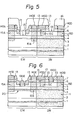
- another mask film 16 of photoresist is formed on the Si0 2 film 13 and the electrodes 14SE, 14DE, 14SD, and 14DD and is patterned to form openings at positions for gates of the enhancement-mode FET and the depletion-mode MESFET, as illustrated in Fig. 5.
- the sio 2 film 13 is selectively etched by a suitable etching method such as a wet chemical etching method and a dry etching method, so that a portion of the GaAs layer 5 in the portion EM and a portion of the contact GaAs layer 7 in the portion DM are exposed in the openings.
- the exposed GaAs layers 5 and 7 are etched by a dry etching method using an etchant which can etch GaAs but cannot substantially etch AlGaAs, so that grooves 17 and 18 with AlGaAs bottoms are formed, as illustrated in Fig. 5.
- a reactive ion etching method using an etchant gas of CC1 2 F 2 and a diluent or carrier gas of helium (He).
- a reactive ion etching method using an etchant gas of CC1 2 F 2 and a diluent or carrier gas of helium (He).
- another electrode metal film for gates is deposited on the exposed portions of the AlGaAs layers 4 and 6 and the mask film 16 by a vacuum evaporation method or a sputtering method.
- the electrode metal film is a multilayer of Ti/Pt/Au and has a thickness of, e.g., approximately 300 mm.
- the electrode metal film may be made of Al or refractory metal silicide (e.g., WSi 2 ).
- the metal film is patterned by a lift-off method to form gate electrodes 19GE and 19GD, as illustrated in Fig. 6.
- the enhancement-mode FET and the depletion-mode MESFET are formed in the portions EM and DM, respectively.
- a layer 20 of two-dimensional electron gas is generated in the upper portion of the undoped GaAs layer 2 adjoining the GaAs/AlGaAs heterojunction plane.
- the exposed surfaces of the AlGaAs within the grooves 17 and 18 preferably are completely covered with the metal film for gates, i.e., the gate electrodes 19 GE and 19 GD.
- the metal film serves as a metal seal so as to prevent the AlGaAs from oxidizing.
- AlGaAs is a very oxidizable material, and an oxide of the AlGaAs is apt to effect the surface concerntration of the two - dimensional electron gas.
- Figure 8 is a schematic partially sectional view of a GaAs semiconductor device comprising an enhancement-mode FET utilizing two-dimensional electron gas and a depletion-mode MESFET similar to that of Fig. 6 but according to a second embodiment of the invention. Portions in Fig. 8 the same as those in Figs. 1 to 6 are referenced by the same numerals.
- the GaAs semiconductor device is manufactured in accordance with the manufacturing process mentioned in the first embodiment, except for the addition of an etching step prior to the deposition of the electrode metal film for source and drain electrodes.
- the exposed contact GaAs layer 7 and the etching stoppable AlGaAs layer 6 are selectively etched by applying, e.g., a wet chemical etching method to form recesses in which portions of the N-type GaAs layer 5 are exposed.
- a wet chemical etching method to form recesses in which portions of the N-type GaAs layer 5 are exposed.
- a process for manufacture of a GaAs semiconductor device comprising an enhancement-mode FET and depletion-mode FET, which utilize two-dimensional electron gas, in accordance with a third embodiment of the present invention will now be explained. As illustrated in Fig. 9 to 12, a process for manufacture of a GaAs semiconductor device comprising an enhancement-mode FET and depletion-mode FET, which utilize two-dimensional electron gas, in accordance with a third embodiment of the present invention will now be explained. As illustrated in Fig.
- a heterojunction semiconductor substrate comprises a semi-insulating GaAs substrate 61, an undoped GaAs layer 62, an undoped AlGaAs layer 63, an N-type AlGaAs layer 64 of an electron-supply layer, a first GaAs layer 65, an etching stoppable AlGaAs layer 66, and a second GaAs layer 67, which layers are formed in sequence on the substrate 1 by an MBE method or an MOCVD method. It is possible to omit the undoped AlGaAs layer 63.
- the thickness of the electron-supply AlGaAs layer 64 is determined within the range of from 25 to 60 nm, depending on the desired threshold voltage of the enhancement-mode FET and the impurity concentration thereof.
- the thickness of the first GaAs layer 65 is determined within the range of from 20 to 200 nm, so as to attain the desired threshold voltage of the depletion-mode FET.
- the thickness of the layer 65 depends on the impurity concentration thereof.
- the thickness of the etching stoppable At y Ga 1-y As layer 66 depends on the etching conditions and the molar rate y of Al and is from 1 to 10 nm, preferably 3 to 6 nm.
- the layers 65, 66, and 67 preferably contain N-type impurities (e.g., silicon), so that they are N-type layers. It is possible to form the layers 65, 66, and 67 without doping of N-type impurities, thus they are i-layers.
- N-type impurities e.g., silicon
- the heterojunction semiconductor substrate comprises the above layers having the following thickness and impurity concentration.
- a mask film (not shown) comprising an Si0 2 film and a Ti/Au film is formed on the second GaAs layer 67 and is selectively etched to form an opening at a boundary region between a portion for the enhancement-mode FET and another portion DM for the depletion-mode FET.
- oxygen ions or protons are doped into the heterojunction semiconductor substrate by an ion-implantation method, so as. to form an isolation region 70, as illustrated in Fig. 10.
- another mask film of photoresist is formed on the GaAs layer 67 and is patterned.
- Portions of the layers 67, 66, and 65 uncovered with the patterned mask film are selectively etched by a wet chemical etching method to form a groove 72 (Fig. 10). In this etching treatment, it is necessary to remove the AlGaAs layer 66, but the first GaAs layer 65 should not be completely removed.
- an Si0 2 film 73 (Fig. 11) is formed over the heterojunction semiconductor substrate and is patterned to form electrode contact windows.
- source electrodes 74SE and 74SD and drain electrodes 74DE and 74DD (Fig. 11) are formed in the manner mentioned in the first embodiment.
- Heat treatment for alloying is carried out to form alloyed regions 75A, 75B, 75C, and 75D.
- another mask film 76 of photoresist is formed on the Si0 2 film 73 and the electrodes 74SE, 74DE, 74SD, and 74DD and is patterned, as illustrated in Fig. 11.
- the Si0 2 film 73 is selectively etched by a suitable etching method.
- the second GaAs layer 67 and the first GaAs layer 65 are selectively etched by a dry etching method using an etchant (CC1 2 F 2 gas) which can etch GaAs but cannot substantially etch AlGaAs, so as to form grooves 77 and 78 (Fig. ll), as mentioned in the first embodiment.
- a dry etching method using an etchant (CC1 2 F 2 gas) which can etch GaAs but cannot substantially etch AlGaAs, so as to form grooves 77 and 78 (Fig. ll), as mentioned in the first embodiment.
- the enhancement-mode FET and the depletion-mode FET are formed in the portions EM and DM, respectively.
- layers 90A and 90B of two-dimensional electron gas are generated in the upper portion of the undoped GaAs layer 62 adjoining the GaAs/AlGaAs heterojunction plane.
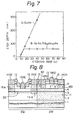
- an average threshold voltage V T of 0.77 V and a high uniformity of threshold voltage V th of the enhancement-mode FET's are obtained, and an average threshold voltage V T of -0.419 V and uniformity of threshold voltage V th shown in Fig. 13 of the depletion-mode FET's are obtained.
- the results of Fig. 13 are obtained from 144 depletion mode FET's.
- the standard deviation a of threshold voltage is 56 mV.
- a comparative example many depletion-mode FET's are formed by using a hetero- junction semiconductor substrate without an etching stoppable AlGaAs layer.
- the results shown in Fig. 14 are obtained from 68 FET's.
- An average threshold voltage V T of -0.50 V and a standard deviation a of threshold voltage of the depletion-mode FET's are obtained.
- the uniformity of threshold voltage of the depletion-mode FET's produced in accordance with the present invention is very superior to that of a conventional case.
- Figure 15 is a schematic partially sectional view of a GaAs semiconductor device of the inverter circuit of Fig. 16 having an E/D construction and similar to that of Fig. 12, according to a fourth embodiment of the present invention. Portions in Fig. 15 the same as those in Figs. 9 to 12 are indicated by the same reference numerals.
- the GaAs semiconductor device is produced in accordance with the production process mentioned in the third embodiment except that the formation of the isolation region 70 of Fig. 12 is not carried out and a common electrode 74A (Fig. 15) is formed instead of the electrodes 74DE and 74SD (Fig. 12).
- Figure 17 is a schematic partially sectional view of a GaAs semiconductor device having an E/D construction and similar to that of Fig. 12, according to a fifth embodiment of the present invention. Portions in Fig. 17 the same as those in Figs. 9 to 12 are indicated by the same reference numerals.
- the GaAs semiconductor device is manufactured in accordance with the process mentioned in the third embodiment except for the addition of an etching step prior to the deposition of the electrode metal film for source and drain electrodes.
- the exposed contact GaAs layer 67 and the etching stoppable AlGaAs layer 66 are selectively etched by applying, e.g., a wet chemical etching method to form recesses in which portions of the N-type GaAs layer 75 are exposed.
- a wet chemical etching method to form recesses in which portions of the N-type GaAs layer 75 are exposed.
- each element (FET) of an E/D construction semiconductor device as well as an E/D inverter having gate metal electrodes formed on the AlGaAs is provided.
- the compound semiconductor under the gate of the enhancement-mode FET comprises an AlGaAs layer, while that under the gate of the depletion-mode FET comprises an AlGaAs layer, a GaAs layer, and an AlGaAs layer.
- the effects brought by forming a GaAs layer between the AlGaAs layers are a decrease of the contact resistance Rc and improvement of the mutual conductance gm.
- AlGaAs for example, Al 0.3 Ga 0.7 As is ⁇ 1.7 eV, larger than that ( ⁇ 1.4 eV) of GaAs, while the electric conductivity of AlGaAs is relatively low (e.g., its electron mobility is about 1/lOth of that of G aAs).
- the AlGaAs has impurities of a deep level which have a complex influence on electrical properties.
- the contact parastic sheet resistance Rs in case of a gate width of 200 ⁇ m is 4 n, smaller than that (10 Q) of a conventional case, which contributes to improvement of the mutual conductance gm.
- the contact resistance Rc is reduced by the addition of the thickness of GaAs. Accordingly, a DCTL circuit having an E/D construction is formed by using the above-mentioned FET's utilizing a heterojunction, whereby the DCFL circuit has the above-mentioned features and a controlled threshold voltage Vth.
- the isolation between an enhancement-mode FET and depletion-mode FET may be attained by forming a groove extending into an undoped GaAs layer through the GaAs/AlGaAs heterojunction instead of the insulator regions 10 and 11 (Fig. 6) or the isolation region 70 (Fig. 12).
- the grooves 17 and 18 (77 and 78) for gate electrodes are formed by a dry etching method. It is preferable to form both the grooves 17 and 18 (77 and 78) simultaneously in the dry etching step, as mentioned above. It is possible to carry out etching for the groove 17 and etching for the groove 18, respectively. Furthermore, it is possible to adopt a wet etching method instead of the dry etching, if selectivity and controllability of the wet etching method are good. In this case, an etching liquid can etch GaAs rapidly and AlGaAs slowly. Such an etching liquid includes a sulfuric acid system liquid and an ammonia system liquid.
- the etch rate of GaAs is about 10 times that of AlGaAs by controlling the H 2 0 2 amount and etching temperature.
- the heterojunction is formed by a combination of GaAs and AlGaAs in the above-mentioend embodiments, it is possible to use combination of AlGaAs-Ge, GaAs-Ge, CdTe-InSb, GaSb-InAs, or the like for the heterojunction.
- a heterojunction of GaAs and AlGaAs is most preferable.
Landscapes
- Junction Field-Effect Transistors (AREA)
- Bipolar Transistors (AREA)
Applications Claiming Priority (2)
| Application Number | Priority Date | Filing Date | Title |
|---|---|---|---|
| JP58042007A JPS59168677A (ja) | 1983-03-14 | 1983-03-14 | 半導体装置及びその製造方法 |
| JP42007/83 | 1983-03-14 |
Publications (3)
| Publication Number | Publication Date |
|---|---|
| EP0119089A2 true EP0119089A2 (de) | 1984-09-19 |
| EP0119089A3 EP0119089A3 (en) | 1985-09-11 |
| EP0119089B1 EP0119089B1 (de) | 1989-01-18 |
Family
ID=12624123
Family Applications (1)
| Application Number | Title | Priority Date | Filing Date |
|---|---|---|---|
| EP84301649A Expired EP0119089B1 (de) | 1983-03-14 | 1984-03-12 | Halbleiteranordnung mit GaAs und Verfahren zu dessen Herstellung |
Country Status (5)
| Country | Link |
|---|---|
| US (2) | US4635343A (de) |
| EP (1) | EP0119089B1 (de) |
| JP (1) | JPS59168677A (de) |
| CA (1) | CA1214575A (de) |
| DE (1) | DE3476294D1 (de) |
Cited By (10)
| Publication number | Priority date | Publication date | Assignee | Title |
|---|---|---|---|---|
| EP0143656A3 (en) * | 1983-11-29 | 1985-09-25 | Fujitsu Limited | Compound semiconductor device and method of producing it |
| EP0175437A1 (de) * | 1984-05-01 | 1986-03-26 | Fujitsu Limited | Herstellung von GaAs-HEMT's des Anreicherungs- und Verarmungstyps |
| US4837178A (en) * | 1984-10-31 | 1989-06-06 | Fujitsu Limited | Method for producing a semiconductor integrated circuit having an improved isolation structure |
| US4855797A (en) * | 1987-07-06 | 1989-08-08 | Siemens Corporate Research And Support, Inc. | Modulation doped high electron mobility transistor with n-i-p-i structure |
| EP0334006A1 (de) * | 1988-02-22 | 1989-09-27 | Siemens Aktiengesellschaft | Heteroübergangsfeldeffekttransistor mit gestapelten Kanalschichten |
| EP0297508A3 (de) * | 1987-07-02 | 1989-10-18 | International Business Machines Corporation | Komplementarische heterostrukturelle Halbleiteranordnung |
| EP0378894A3 (de) * | 1988-12-28 | 1990-11-28 | AT&T Corp. | Herstellung von integrierten Schaltungen aus GaAs |
| EP0397148A3 (de) * | 1989-05-10 | 1991-05-15 | Fujitsu Limited | Heterostrukturbauelement und dessen Herstellungsverfahren |
| EP0575789A1 (de) * | 1992-06-15 | 1993-12-29 | Daimler-Benz Aktiengesellschaft | Monolithisch integrierter Millimeterwellenschaltkreis und Verfahren zu dessen Herstellung |
| EP0439195A3 (en) * | 1990-01-26 | 1996-07-31 | Fujitsu Ltd | Method for fabricating a semiconductor device including a semi-insulating semiconductor layer |
Families Citing this family (52)
| Publication number | Priority date | Publication date | Assignee | Title |
|---|---|---|---|---|
| DE3679618D1 (de) * | 1985-08-26 | 1991-07-11 | Matsushita Electric Industrial Co Ltd | Halbleiterbauelement mit einem abrupten uebergang und verfahren zu seiner herstellung mittels epitaxie. |
| US4916498A (en) * | 1985-09-15 | 1990-04-10 | Trw Inc. | High electron mobility power transistor |
| US4746627A (en) * | 1986-10-30 | 1988-05-24 | Mcdonnell Douglas Corporation | Method of making complementary GaAs heterojunction transistors |
| JPS63198320A (ja) * | 1987-02-13 | 1988-08-17 | Mitsubishi Electric Corp | 結晶成長方法 |
| US5229323A (en) * | 1987-08-21 | 1993-07-20 | Kabushiki Kaisha Toshiba | Method for manufacturing a semiconductor device with Schottky electrodes |
| DE3850855T2 (de) * | 1987-11-13 | 1994-11-10 | Nissan Motor | Halbleitervorrichtung. |
| US4897361A (en) * | 1987-12-14 | 1990-01-30 | American Telephone & Telegraph Company, At&T Bell Laboratories | Patterning method in the manufacture of miniaturized devices |
| USH596H (en) | 1988-02-16 | 1989-03-07 | The United States Of America As Represented By The Secretary Of The Army | Method of etching titanium diboride |
| US5192701A (en) * | 1988-03-17 | 1993-03-09 | Kabushiki Kaisha Toshiba | Method of manufacturing field effect transistors having different threshold voltages |
| US5138408A (en) * | 1988-04-15 | 1992-08-11 | Nec Corporation | Resonant tunneling hot carrier transistor |
| US4946548A (en) * | 1988-04-29 | 1990-08-07 | Toyoda Gosei Co., Ltd. | Dry etching method for semiconductor |
| DE68928395T2 (de) * | 1988-06-28 | 1998-05-14 | Nippon Electric Co | Halbleitervorrichtung mit Verbindungshalbleiterfet mit E/D-Struktur mit hoher Geräuschmarge |
| US5091759A (en) * | 1989-10-30 | 1992-02-25 | Texas Instruments Incorporated | Heterostructure field effect transistor |
| US5012318A (en) * | 1988-09-05 | 1991-04-30 | Nec Corporation | Hybrid semiconductor device implemented by combination of heterojunction bipolar transistor and field effect transistor |
| JP2630445B2 (ja) * | 1988-10-08 | 1997-07-16 | 富士通株式会社 | 半導体装置 |
| JPH02148740A (ja) * | 1988-11-29 | 1990-06-07 | Fujitsu Ltd | 半導体装置及びその製造方法 |
| JP2687519B2 (ja) * | 1988-12-06 | 1997-12-08 | 日本電気株式会社 | 半導体装置及びその製造方法 |
| US5139968A (en) * | 1989-03-03 | 1992-08-18 | Mitsubishi Denki Kabushiki Kaisha | Method of producing a t-shaped gate electrode |
| US5276340A (en) * | 1989-11-21 | 1994-01-04 | Fujitsu Limited | Semiconductor integrated circuit having a reduced side gate effect |
| JP2553723B2 (ja) * | 1989-12-25 | 1996-11-13 | 三菱電機株式会社 | 化合物半導体集積回路装置 |
| JP3078821B2 (ja) * | 1990-05-30 | 2000-08-21 | 豊田合成株式会社 | 半導体のドライエッチング方法 |
| JP2551203B2 (ja) * | 1990-06-05 | 1996-11-06 | 三菱電機株式会社 | 半導体装置 |
| JPH04280436A (ja) * | 1990-09-28 | 1992-10-06 | Motorola Inc | 相補型自己整合hfetの製造方法 |
| JPH04260338A (ja) * | 1991-02-14 | 1992-09-16 | Mitsubishi Electric Corp | 半導体装置の製造方法 |
| US5116774A (en) * | 1991-03-22 | 1992-05-26 | Motorola, Inc. | Heterojunction method and structure |
| CA2067025A1 (en) * | 1991-04-26 | 1992-10-27 | Nobuo Shiga | Multi-stage amplifier device and method for producing the same |
| US5252842A (en) * | 1991-07-26 | 1993-10-12 | Westinghouse Electric Corp. | Low-loss semiconductor device and backside etching method for manufacturing same |
| US5453627A (en) * | 1992-05-14 | 1995-09-26 | Nippon Telegraph And Telephone Corporation | Quantum interference device and complementary logic circuit utilizing thereof |
| US5254492A (en) * | 1992-11-10 | 1993-10-19 | Texas Instruments Incorporated | Method of fabricating an integrated circuit for providing low-noise and high-power microwave operation |
| US5514605A (en) * | 1994-08-24 | 1996-05-07 | Nec Corporation | Fabrication process for compound semiconductor device |
| JPH0936133A (ja) * | 1995-07-14 | 1997-02-07 | Mitsubishi Electric Corp | 半導体装置およびその製造方法 |
| JP3616447B2 (ja) * | 1996-02-27 | 2005-02-02 | 富士通株式会社 | 半導体装置 |
| JP2891204B2 (ja) * | 1996-09-27 | 1999-05-17 | 日本電気株式会社 | 半導体装置の製造方法 |
| JP3147009B2 (ja) | 1996-10-30 | 2001-03-19 | 日本電気株式会社 | 電界効果トランジスタ及びその製造方法 |
| JP3123940B2 (ja) * | 1997-03-27 | 2001-01-15 | 日本電気株式会社 | 電界効果トランジスタおよびその製造方法 |
| WO2003050849A2 (en) * | 2001-12-06 | 2003-06-19 | Hrl Laboratories, Llc | High power-low noise microwave gan heterojunction field effet transistor |
| JP4230370B2 (ja) * | 2004-01-16 | 2009-02-25 | ユーディナデバイス株式会社 | 半導体装置及びその製造方法 |
| US20060009038A1 (en) | 2004-07-12 | 2006-01-12 | International Business Machines Corporation | Processing for overcoming extreme topography |
| KR100712753B1 (ko) * | 2005-03-09 | 2007-04-30 | 주식회사 실트론 | 화합물 반도체 장치 및 그 제조방법 |
| US7808016B2 (en) * | 2006-09-14 | 2010-10-05 | Teledyne Licensing, Llc | Heterogeneous integration of low noise amplifiers with power amplifiers or switches |
| EP2040299A1 (de) * | 2007-09-12 | 2009-03-25 | Forschungsverbund Berlin e.V. | Elektronische Bauelemente mit verbesserten Transfercharakteristiken und Methode zur Optimierung der Transfercharakteristiken solcher elektronischen Bauelementen. |
| KR100894810B1 (ko) | 2007-09-19 | 2009-04-24 | 전자부품연구원 | 고전자 이동도 트랜지스터 및 그 제조방법 |
| WO2010151857A2 (en) | 2009-06-26 | 2010-12-29 | Cornell University | Method for forming iii-v semiconductor structures including aluminum-silicon nitride passivation |
| WO2010151856A2 (en) | 2009-06-26 | 2010-12-29 | Cornell University | Chemical vapor deposition process for aluminum silicon nitride |
| US8138529B2 (en) | 2009-11-02 | 2012-03-20 | Transphorm Inc. | Package configurations for low EMI circuits |
| JP5499692B2 (ja) * | 2009-12-24 | 2014-05-21 | トヨタ自動車株式会社 | 半導体装置及びその製造方法 |
| KR101923972B1 (ko) * | 2012-12-18 | 2018-11-30 | 한국전자통신연구원 | 트랜지스터 및 그 제조 방법 |
| US9530708B1 (en) | 2013-05-31 | 2016-12-27 | Hrl Laboratories, Llc | Flexible electronic circuit and method for manufacturing same |
| CN103985747B (zh) * | 2014-05-27 | 2017-03-29 | 中国科学技术大学 | GaAs/AlGaAs半导体异质结结构的霍尔棒及其制作方法 |
| US11139290B2 (en) * | 2018-09-28 | 2021-10-05 | Taiwan Semiconductor Manufacturing Company, Ltd. | High voltage cascode HEMT device |
| CN110429028B (zh) * | 2019-08-01 | 2021-11-19 | 福建省福联集成电路有限公司 | 一种晶体管器件增强型和耗尽型栅极集成制作方法及器件 |
| WO2024113076A1 (en) * | 2022-11-28 | 2024-06-06 | Innoscience (suzhou) Semiconductor Co., Ltd. | Semiconductor device and manufacturing method thereof |
Family Cites Families (9)
| Publication number | Priority date | Publication date | Assignee | Title |
|---|---|---|---|---|
| US4163237A (en) * | 1978-04-24 | 1979-07-31 | Bell Telephone Laboratories, Incorporated | High mobility multilayered heterojunction devices employing modulated doping |
| US4212020A (en) * | 1978-07-21 | 1980-07-08 | California Institute Of Technology | Solid state electro-optical devices on a semi-insulating substrate |
| FR2465317A2 (fr) * | 1979-03-28 | 1981-03-20 | Thomson Csf | Transistor a effet de champ a frequence de coupure elevee |
| DE3279795D1 (en) * | 1981-04-23 | 1989-08-03 | Fujitsu Ltd | High electron mobility semiconductor device |
| US4371968A (en) * | 1981-07-01 | 1983-02-01 | The United States Of America As Represented By The Secretary Of The Army | Monolithic injection laser arrays formed by crystal regrowth techniques |
| JPS5891682A (ja) * | 1981-11-27 | 1983-05-31 | Hitachi Ltd | 半導体装置 |
| JPS58143577A (ja) * | 1982-02-22 | 1983-08-26 | Toshiba Corp | 埋め込みゲ−ト電界効果トランジスタの製造方法 |
| US4523961A (en) * | 1982-11-12 | 1985-06-18 | At&T Bell Laboratories | Method of improving current confinement in semiconductor lasers by inert ion bombardment |
| US4545109A (en) * | 1983-01-21 | 1985-10-08 | Rca Corporation | Method of making a gallium arsenide field effect transistor |
-
1983
- 1983-03-14 JP JP58042007A patent/JPS59168677A/ja active Granted
-
1984
- 1984-03-09 US US06/587,967 patent/US4635343A/en not_active Expired - Lifetime
- 1984-03-12 CA CA000449399A patent/CA1214575A/en not_active Expired
- 1984-03-12 DE DE8484301649T patent/DE3476294D1/de not_active Expired
- 1984-03-12 EP EP84301649A patent/EP0119089B1/de not_active Expired
-
1986
- 1986-09-19 US US06/909,464 patent/US4733283A/en not_active Expired - Lifetime
Cited By (14)
| Publication number | Priority date | Publication date | Assignee | Title |
|---|---|---|---|---|
| US4849368A (en) * | 1983-11-29 | 1989-07-18 | Fujitsu Limited | Method of producing a two-dimensional electron gas semiconductor device |
| EP0143656A3 (en) * | 1983-11-29 | 1985-09-25 | Fujitsu Limited | Compound semiconductor device and method of producing it |
| EP0175437A1 (de) * | 1984-05-01 | 1986-03-26 | Fujitsu Limited | Herstellung von GaAs-HEMT's des Anreicherungs- und Verarmungstyps |
| US4615102A (en) * | 1984-05-01 | 1986-10-07 | Fujitsu Limited | Method of producing enhancement mode and depletion mode FETs |
| US4837178A (en) * | 1984-10-31 | 1989-06-06 | Fujitsu Limited | Method for producing a semiconductor integrated circuit having an improved isolation structure |
| EP0297508A3 (de) * | 1987-07-02 | 1989-10-18 | International Business Machines Corporation | Komplementarische heterostrukturelle Halbleiteranordnung |
| US4855797A (en) * | 1987-07-06 | 1989-08-08 | Siemens Corporate Research And Support, Inc. | Modulation doped high electron mobility transistor with n-i-p-i structure |
| EP0334006A1 (de) * | 1988-02-22 | 1989-09-27 | Siemens Aktiengesellschaft | Heteroübergangsfeldeffekttransistor mit gestapelten Kanalschichten |
| EP0378894A3 (de) * | 1988-12-28 | 1990-11-28 | AT&T Corp. | Herstellung von integrierten Schaltungen aus GaAs |
| US5041393A (en) * | 1988-12-28 | 1991-08-20 | At&T Bell Laboratories | Fabrication of GaAs integrated circuits |
| EP0397148A3 (de) * | 1989-05-10 | 1991-05-15 | Fujitsu Limited | Heterostrukturbauelement und dessen Herstellungsverfahren |
| US5170230A (en) * | 1989-05-10 | 1992-12-08 | Fujitsu Limited | Semiconductor device and production method thereof |
| EP0439195A3 (en) * | 1990-01-26 | 1996-07-31 | Fujitsu Ltd | Method for fabricating a semiconductor device including a semi-insulating semiconductor layer |
| EP0575789A1 (de) * | 1992-06-15 | 1993-12-29 | Daimler-Benz Aktiengesellschaft | Monolithisch integrierter Millimeterwellenschaltkreis und Verfahren zu dessen Herstellung |
Also Published As
| Publication number | Publication date |
|---|---|
| JPS59168677A (ja) | 1984-09-22 |
| CA1214575A (en) | 1986-11-25 |
| EP0119089A3 (en) | 1985-09-11 |
| JPH0437582B2 (de) | 1992-06-19 |
| DE3476294D1 (en) | 1989-02-23 |
| EP0119089B1 (de) | 1989-01-18 |
| US4733283A (en) | 1988-03-22 |
| US4635343A (en) | 1987-01-13 |
Similar Documents
| Publication | Publication Date | Title |
|---|---|---|
| EP0119089B1 (de) | Halbleiteranordnung mit GaAs und Verfahren zu dessen Herstellung | |
| US4849368A (en) | Method of producing a two-dimensional electron gas semiconductor device | |
| EP0175437B1 (de) | Herstellung von GaAs-HEMT's des Anreicherungs- und Verarmungstyps | |
| US5041393A (en) | Fabrication of GaAs integrated circuits | |
| US5350709A (en) | Method of doping a group III-V compound semiconductor | |
| KR930000603B1 (ko) | 반도체장치 및 그 제조방법 | |
| US4717685A (en) | Method for producing a metal semiconductor field effect transistor | |
| US5334865A (en) | MODFET structure for threshold control | |
| US5231040A (en) | Method of making a field effect transistor | |
| EP0833379A2 (de) | Halbleiterbauelement und Verfahren zu seiner Herstellung | |
| GB2217108A (en) | Semiconductor device etching using indium containing etch stop | |
| JP3858888B2 (ja) | エッチング方法及び半導体装置の製造方法 | |
| JP2551427B2 (ja) | 半導体装置及びその製造方法 | |
| KR890003416B1 (ko) | 반도체 장치 및 그의 제조방법 | |
| JPH10125695A (ja) | 半導体装置およびその製造方法 | |
| JP2000353789A (ja) | 化合物半導体装置およびその製造方法 | |
| JPH0429225B2 (de) | ||
| JPH10125698A (ja) | 半導体装置およびその製造方法 | |
| JP3109097B2 (ja) | 電界効果トランジスタの製造方法およびエッチング方法 | |
| JPH1197452A (ja) | 半導体装置 | |
| JPH0810701B2 (ja) | 接合型電界効果トランジスタの製造方法 | |
| JPH0123955B2 (de) | ||
| JPH01107577A (ja) | 電界効果トランジスタの製造方法 | |
| JPS628573A (ja) | 半導体装置およびその製造方法 | |
| JPH0846146A (ja) | 半導体集積回路の製造方法 |
Legal Events
| Date | Code | Title | Description |
|---|---|---|---|
| PUAI | Public reference made under article 153(3) epc to a published international application that has entered the european phase |
Free format text: ORIGINAL CODE: 0009012 |
|
| AK | Designated contracting states |
Designated state(s): DE FR GB IT |
|
| PUAL | Search report despatched |
Free format text: ORIGINAL CODE: 0009013 |
|
| AK | Designated contracting states |
Designated state(s): DE FR GB IT |
|
| 17P | Request for examination filed |
Effective date: 19860218 |
|
| 17Q | First examination report despatched |
Effective date: 19880318 |
|
| GRAA | (expected) grant |
Free format text: ORIGINAL CODE: 0009210 |
|
| AK | Designated contracting states |
Kind code of ref document: B1 Designated state(s): DE FR GB IT |
|
| REF | Corresponds to: |
Ref document number: 3476294 Country of ref document: DE Date of ref document: 19890223 |
|
| ET | Fr: translation filed | ||
| ITF | It: translation for a ep patent filed | ||
| PLBE | No opposition filed within time limit |
Free format text: ORIGINAL CODE: 0009261 |
|
| STAA | Information on the status of an ep patent application or granted ep patent |
Free format text: STATUS: NO OPPOSITION FILED WITHIN TIME LIMIT |
|
| 26N | No opposition filed | ||
| ITTA | It: last paid annual fee | ||
| REG | Reference to a national code |
Ref country code: GB Ref legal event code: IF02 |
|
| PGFP | Annual fee paid to national office [announced via postgrant information from national office to epo] |
Ref country code: FR Payment date: 20030310 Year of fee payment: 20 |
|
| PGFP | Annual fee paid to national office [announced via postgrant information from national office to epo] |
Ref country code: GB Payment date: 20030312 Year of fee payment: 20 |
|
| PGFP | Annual fee paid to national office [announced via postgrant information from national office to epo] |
Ref country code: DE Payment date: 20030320 Year of fee payment: 20 |
|
| PG25 | Lapsed in a contracting state [announced via postgrant information from national office to epo] |
Ref country code: GB Free format text: LAPSE BECAUSE OF EXPIRATION OF PROTECTION Effective date: 20040311 |
|
| REG | Reference to a national code |
Ref country code: GB Ref legal event code: PE20 |