EP0325828B1 - Procédé pour fabriquer des éléments profilés - Google Patents
Procédé pour fabriquer des éléments profilés Download PDFInfo
- Publication number
- EP0325828B1 EP0325828B1 EP88303433A EP88303433A EP0325828B1 EP 0325828 B1 EP0325828 B1 EP 0325828B1 EP 88303433 A EP88303433 A EP 88303433A EP 88303433 A EP88303433 A EP 88303433A EP 0325828 B1 EP0325828 B1 EP 0325828B1
- Authority
- EP
- European Patent Office
- Prior art keywords
- molding member
- synthetic resin
- resin material
- section
- continuous body
- Prior art date
- Legal status (The legal status is an assumption and is not a legal conclusion. Google has not performed a legal analysis and makes no representation as to the accuracy of the status listed.)
- Expired - Lifetime
Links
- 238000000465 moulding Methods 0.000 title claims description 79
- 238000000034 method Methods 0.000 title claims description 24
- 239000000463 material Substances 0.000 claims description 39
- 229920003002 synthetic resin Polymers 0.000 claims description 30
- 239000000057 synthetic resin Substances 0.000 claims description 30
- 238000001125 extrusion Methods 0.000 claims description 14
- XLYOFNOQVPJJNP-UHFFFAOYSA-N water Substances O XLYOFNOQVPJJNP-UHFFFAOYSA-N 0.000 claims description 4
- 238000005520 cutting process Methods 0.000 description 10
- 238000004519 manufacturing process Methods 0.000 description 7
- 238000001746 injection moulding Methods 0.000 description 6
- 239000002184 metal Substances 0.000 description 6
- 239000000853 adhesive Substances 0.000 description 5
- 230000001070 adhesive effect Effects 0.000 description 5
- 229920005989 resin Polymers 0.000 description 4
- 239000011347 resin Substances 0.000 description 4
- 238000010586 diagram Methods 0.000 description 3
- 238000004140 cleaning Methods 0.000 description 2
- 239000002131 composite material Substances 0.000 description 2
- 238000001816 cooling Methods 0.000 description 2
- 238000006073 displacement reaction Methods 0.000 description 2
- 229920001971 elastomer Polymers 0.000 description 2
- 238000005516 engineering process Methods 0.000 description 2
- 239000005038 ethylene vinyl acetate Substances 0.000 description 2
- 239000002932 luster Substances 0.000 description 2
- 238000012986 modification Methods 0.000 description 2
- 230000004048 modification Effects 0.000 description 2
- 229920001200 poly(ethylene-vinyl acetate) Polymers 0.000 description 2
- 230000001681 protective effect Effects 0.000 description 2
- 230000002441 reversible effect Effects 0.000 description 2
- 239000005060 rubber Substances 0.000 description 2
- 239000004925 Acrylic resin Substances 0.000 description 1
- 229920000178 Acrylic resin Polymers 0.000 description 1
- BMTAFVWTTFSTOG-UHFFFAOYSA-N Butylate Chemical compound CCSC(=O)N(CC(C)C)CC(C)C BMTAFVWTTFSTOG-UHFFFAOYSA-N 0.000 description 1
- 230000015572 biosynthetic process Effects 0.000 description 1
- 229920002301 cellulose acetate Polymers 0.000 description 1
- 239000011248 coating agent Substances 0.000 description 1
- 238000000576 coating method Methods 0.000 description 1
- 230000003247 decreasing effect Effects 0.000 description 1
- 238000005238 degreasing Methods 0.000 description 1
- 230000006866 deterioration Effects 0.000 description 1
- 239000011521 glass Substances 0.000 description 1
- 229920000554 ionomer Polymers 0.000 description 1
- 239000004431 polycarbonate resin Substances 0.000 description 1
- 229920005668 polycarbonate resin Polymers 0.000 description 1
- 239000004800 polyvinyl chloride Substances 0.000 description 1
- 238000002360 preparation method Methods 0.000 description 1
- 238000007493 shaping process Methods 0.000 description 1
- 229920003051 synthetic elastomer Polymers 0.000 description 1
- 239000005061 synthetic rubber Substances 0.000 description 1
- 229920001169 thermoplastic Polymers 0.000 description 1
- 239000004416 thermosoftening plastic Substances 0.000 description 1
Images


Classifications
-
- B—PERFORMING OPERATIONS; TRANSPORTING
- B60—VEHICLES IN GENERAL
- B60J—WINDOWS, WINDSCREENS, NON-FIXED ROOFS, DOORS, OR SIMILAR DEVICES FOR VEHICLES; REMOVABLE EXTERNAL PROTECTIVE COVERINGS SPECIALLY ADAPTED FOR VEHICLES
- B60J1/00—Windows; Windscreens; Accessories therefor
- B60J1/20—Accessories, e.g. wind deflectors, blinds
- B60J1/2002—Wind deflectors specially adapted for preventing soiling, e.g. for side windows
-
- B—PERFORMING OPERATIONS; TRANSPORTING
- B26—HAND CUTTING TOOLS; CUTTING; SEVERING
- B26D—CUTTING; DETAILS COMMON TO MACHINES FOR PERFORATING, PUNCHING, CUTTING-OUT, STAMPING-OUT OR SEVERING
- B26D1/00—Cutting through work characterised by the nature or movement of the cutting member or particular materials not otherwise provided for; Apparatus or machines therefor; Cutting members therefor
- B26D1/01—Cutting through work characterised by the nature or movement of the cutting member or particular materials not otherwise provided for; Apparatus or machines therefor; Cutting members therefor involving a cutting member which does not travel with the work
- B26D1/02—Cutting through work characterised by the nature or movement of the cutting member or particular materials not otherwise provided for; Apparatus or machines therefor; Cutting members therefor involving a cutting member which does not travel with the work having a stationary cutting member
-
- B—PERFORMING OPERATIONS; TRANSPORTING
- B26—HAND CUTTING TOOLS; CUTTING; SEVERING
- B26D—CUTTING; DETAILS COMMON TO MACHINES FOR PERFORATING, PUNCHING, CUTTING-OUT, STAMPING-OUT OR SEVERING
- B26D1/00—Cutting through work characterised by the nature or movement of the cutting member or particular materials not otherwise provided for; Apparatus or machines therefor; Cutting members therefor
- B26D1/01—Cutting through work characterised by the nature or movement of the cutting member or particular materials not otherwise provided for; Apparatus or machines therefor; Cutting members therefor involving a cutting member which does not travel with the work
- B26D1/12—Cutting through work characterised by the nature or movement of the cutting member or particular materials not otherwise provided for; Apparatus or machines therefor; Cutting members therefor involving a cutting member which does not travel with the work having a cutting member moving about an axis
- B26D1/14—Cutting through work characterised by the nature or movement of the cutting member or particular materials not otherwise provided for; Apparatus or machines therefor; Cutting members therefor involving a cutting member which does not travel with the work having a cutting member moving about an axis with a circular cutting member, e.g. disc cutter
- B26D1/20—Cutting through work characterised by the nature or movement of the cutting member or particular materials not otherwise provided for; Apparatus or machines therefor; Cutting members therefor involving a cutting member which does not travel with the work having a cutting member moving about an axis with a circular cutting member, e.g. disc cutter coacting with a fixed member
-
- B—PERFORMING OPERATIONS; TRANSPORTING
- B26—HAND CUTTING TOOLS; CUTTING; SEVERING
- B26D—CUTTING; DETAILS COMMON TO MACHINES FOR PERFORATING, PUNCHING, CUTTING-OUT, STAMPING-OUT OR SEVERING
- B26D3/00—Cutting work characterised by the nature of the cut made; Apparatus therefor
- B26D3/28—Splitting layers from work; Mutually separating layers by cutting
-
- B—PERFORMING OPERATIONS; TRANSPORTING
- B29—WORKING OF PLASTICS; WORKING OF SUBSTANCES IN A PLASTIC STATE IN GENERAL
- B29C—SHAPING OR JOINING OF PLASTICS; SHAPING OF MATERIAL IN A PLASTIC STATE, NOT OTHERWISE PROVIDED FOR; AFTER-TREATMENT OF THE SHAPED PRODUCTS, e.g. REPAIRING
- B29C48/00—Extrusion moulding, i.e. expressing the moulding material through a die or nozzle which imparts the desired form; Apparatus therefor
- B29C48/001—Combinations of extrusion moulding with other shaping operations
- B29C48/0019—Combinations of extrusion moulding with other shaping operations combined with shaping by flattening, folding or bending
-
- B—PERFORMING OPERATIONS; TRANSPORTING
- B29—WORKING OF PLASTICS; WORKING OF SUBSTANCES IN A PLASTIC STATE IN GENERAL
- B29C—SHAPING OR JOINING OF PLASTICS; SHAPING OF MATERIAL IN A PLASTIC STATE, NOT OTHERWISE PROVIDED FOR; AFTER-TREATMENT OF THE SHAPED PRODUCTS, e.g. REPAIRING
- B29C48/00—Extrusion moulding, i.e. expressing the moulding material through a die or nozzle which imparts the desired form; Apparatus therefor
- B29C48/001—Combinations of extrusion moulding with other shaping operations
- B29C48/0022—Combinations of extrusion moulding with other shaping operations combined with cutting
-
- B—PERFORMING OPERATIONS; TRANSPORTING
- B29—WORKING OF PLASTICS; WORKING OF SUBSTANCES IN A PLASTIC STATE IN GENERAL
- B29C—SHAPING OR JOINING OF PLASTICS; SHAPING OF MATERIAL IN A PLASTIC STATE, NOT OTHERWISE PROVIDED FOR; AFTER-TREATMENT OF THE SHAPED PRODUCTS, e.g. REPAIRING
- B29C48/00—Extrusion moulding, i.e. expressing the moulding material through a die or nozzle which imparts the desired form; Apparatus therefor
- B29C48/03—Extrusion moulding, i.e. expressing the moulding material through a die or nozzle which imparts the desired form; Apparatus therefor characterised by the shape of the extruded material at extrusion
- B29C48/12—Articles with an irregular circumference when viewed in cross-section, e.g. window profiles
-
- B—PERFORMING OPERATIONS; TRANSPORTING
- B29—WORKING OF PLASTICS; WORKING OF SUBSTANCES IN A PLASTIC STATE IN GENERAL
- B29C—SHAPING OR JOINING OF PLASTICS; SHAPING OF MATERIAL IN A PLASTIC STATE, NOT OTHERWISE PROVIDED FOR; AFTER-TREATMENT OF THE SHAPED PRODUCTS, e.g. REPAIRING
- B29C48/00—Extrusion moulding, i.e. expressing the moulding material through a die or nozzle which imparts the desired form; Apparatus therefor
- B29C48/15—Extrusion moulding, i.e. expressing the moulding material through a die or nozzle which imparts the desired form; Apparatus therefor incorporating preformed parts or layers, e.g. extrusion moulding around inserts
- B29C48/154—Coating solid articles, i.e. non-hollow articles
- B29C48/155—Partial coating thereof
-
- B—PERFORMING OPERATIONS; TRANSPORTING
- B29—WORKING OF PLASTICS; WORKING OF SUBSTANCES IN A PLASTIC STATE IN GENERAL
- B29C—SHAPING OR JOINING OF PLASTICS; SHAPING OF MATERIAL IN A PLASTIC STATE, NOT OTHERWISE PROVIDED FOR; AFTER-TREATMENT OF THE SHAPED PRODUCTS, e.g. REPAIRING
- B29C48/00—Extrusion moulding, i.e. expressing the moulding material through a die or nozzle which imparts the desired form; Apparatus therefor
- B29C48/25—Component parts, details or accessories; Auxiliary operations
- B29C48/30—Extrusion nozzles or dies
- B29C48/302—Extrusion nozzles or dies being adjustable, i.e. having adjustable exit sections
-
- B—PERFORMING OPERATIONS; TRANSPORTING
- B29—WORKING OF PLASTICS; WORKING OF SUBSTANCES IN A PLASTIC STATE IN GENERAL
- B29C—SHAPING OR JOINING OF PLASTICS; SHAPING OF MATERIAL IN A PLASTIC STATE, NOT OTHERWISE PROVIDED FOR; AFTER-TREATMENT OF THE SHAPED PRODUCTS, e.g. REPAIRING
- B29C48/00—Extrusion moulding, i.e. expressing the moulding material through a die or nozzle which imparts the desired form; Apparatus therefor
- B29C48/25—Component parts, details or accessories; Auxiliary operations
- B29C48/92—Measuring, controlling or regulating
-
- B—PERFORMING OPERATIONS; TRANSPORTING
- B29—WORKING OF PLASTICS; WORKING OF SUBSTANCES IN A PLASTIC STATE IN GENERAL
- B29C—SHAPING OR JOINING OF PLASTICS; SHAPING OF MATERIAL IN A PLASTIC STATE, NOT OTHERWISE PROVIDED FOR; AFTER-TREATMENT OF THE SHAPED PRODUCTS, e.g. REPAIRING
- B29C67/00—Shaping techniques not covered by groups B29C39/00 - B29C65/00, B29C70/00 or B29C73/00
- B29C67/0044—Shaping techniques not covered by groups B29C39/00 - B29C65/00, B29C70/00 or B29C73/00 for shaping edges or extremities
-
- B—PERFORMING OPERATIONS; TRANSPORTING
- B60—VEHICLES IN GENERAL
- B60J—WINDOWS, WINDSCREENS, NON-FIXED ROOFS, DOORS, OR SIMILAR DEVICES FOR VEHICLES; REMOVABLE EXTERNAL PROTECTIVE COVERINGS SPECIALLY ADAPTED FOR VEHICLES
- B60J1/00—Windows; Windscreens; Accessories therefor
- B60J1/02—Windows; Windscreens; Accessories therefor arranged at the vehicle front, e.g. structure of the glazing, mounting of the glazing
-
- B—PERFORMING OPERATIONS; TRANSPORTING
- B60—VEHICLES IN GENERAL
- B60J—WINDOWS, WINDSCREENS, NON-FIXED ROOFS, DOORS, OR SIMILAR DEVICES FOR VEHICLES; REMOVABLE EXTERNAL PROTECTIVE COVERINGS SPECIALLY ADAPTED FOR VEHICLES
- B60J10/00—Sealing arrangements
- B60J10/15—Sealing arrangements characterised by the material
- B60J10/18—Sealing arrangements characterised by the material provided with reinforcements or inserts
-
- B—PERFORMING OPERATIONS; TRANSPORTING
- B60—VEHICLES IN GENERAL
- B60J—WINDOWS, WINDSCREENS, NON-FIXED ROOFS, DOORS, OR SIMILAR DEVICES FOR VEHICLES; REMOVABLE EXTERNAL PROTECTIVE COVERINGS SPECIALLY ADAPTED FOR VEHICLES
- B60J10/00—Sealing arrangements
- B60J10/20—Sealing arrangements characterised by the shape
- B60J10/21—Sealing arrangements characterised by the shape having corner parts or bends
-
- B—PERFORMING OPERATIONS; TRANSPORTING
- B60—VEHICLES IN GENERAL
- B60J—WINDOWS, WINDSCREENS, NON-FIXED ROOFS, DOORS, OR SIMILAR DEVICES FOR VEHICLES; REMOVABLE EXTERNAL PROTECTIVE COVERINGS SPECIALLY ADAPTED FOR VEHICLES
- B60J10/00—Sealing arrangements
- B60J10/20—Sealing arrangements characterised by the shape
- B60J10/22—Sealing arrangements characterised by the shape having varying cross-section in the longitudinal direction
-
- B—PERFORMING OPERATIONS; TRANSPORTING
- B60—VEHICLES IN GENERAL
- B60J—WINDOWS, WINDSCREENS, NON-FIXED ROOFS, DOORS, OR SIMILAR DEVICES FOR VEHICLES; REMOVABLE EXTERNAL PROTECTIVE COVERINGS SPECIALLY ADAPTED FOR VEHICLES
- B60J10/00—Sealing arrangements
- B60J10/20—Sealing arrangements characterised by the shape
- B60J10/25—Sealing arrangements characterised by the shape characterised by water drainage means
-
- B—PERFORMING OPERATIONS; TRANSPORTING
- B60—VEHICLES IN GENERAL
- B60J—WINDOWS, WINDSCREENS, NON-FIXED ROOFS, DOORS, OR SIMILAR DEVICES FOR VEHICLES; REMOVABLE EXTERNAL PROTECTIVE COVERINGS SPECIALLY ADAPTED FOR VEHICLES
- B60J10/00—Sealing arrangements
- B60J10/20—Sealing arrangements characterised by the shape
- B60J10/26—Sealing arrangements characterised by the shape characterised by the surface shape
- B60J10/265—Sealing arrangements characterised by the shape characterised by the surface shape the surface being primarily decorative
-
- B—PERFORMING OPERATIONS; TRANSPORTING
- B60—VEHICLES IN GENERAL
- B60J—WINDOWS, WINDSCREENS, NON-FIXED ROOFS, DOORS, OR SIMILAR DEVICES FOR VEHICLES; REMOVABLE EXTERNAL PROTECTIVE COVERINGS SPECIALLY ADAPTED FOR VEHICLES
- B60J10/00—Sealing arrangements
- B60J10/70—Sealing arrangements specially adapted for windows or windscreens
-
- B—PERFORMING OPERATIONS; TRANSPORTING
- B60—VEHICLES IN GENERAL
- B60J—WINDOWS, WINDSCREENS, NON-FIXED ROOFS, DOORS, OR SIMILAR DEVICES FOR VEHICLES; REMOVABLE EXTERNAL PROTECTIVE COVERINGS SPECIALLY ADAPTED FOR VEHICLES
- B60J10/00—Sealing arrangements
- B60J10/80—Sealing arrangements specially adapted for opening panels, e.g. doors
-
- B—PERFORMING OPERATIONS; TRANSPORTING
- B60—VEHICLES IN GENERAL
- B60R—VEHICLES, VEHICLE FITTINGS, OR VEHICLE PARTS, NOT OTHERWISE PROVIDED FOR
- B60R13/00—Elements for body-finishing, identifying, or decorating; Arrangements or adaptations for advertising purposes
- B60R13/07—Water drainage or guide means not integral with roof structure
-
- B—PERFORMING OPERATIONS; TRANSPORTING
- B29—WORKING OF PLASTICS; WORKING OF SUBSTANCES IN A PLASTIC STATE IN GENERAL
- B29C—SHAPING OR JOINING OF PLASTICS; SHAPING OF MATERIAL IN A PLASTIC STATE, NOT OTHERWISE PROVIDED FOR; AFTER-TREATMENT OF THE SHAPED PRODUCTS, e.g. REPAIRING
- B29C2793/00—Shaping techniques involving a cutting or machining operation
- B29C2793/0027—Cutting off
-
- B—PERFORMING OPERATIONS; TRANSPORTING
- B29—WORKING OF PLASTICS; WORKING OF SUBSTANCES IN A PLASTIC STATE IN GENERAL
- B29C—SHAPING OR JOINING OF PLASTICS; SHAPING OF MATERIAL IN A PLASTIC STATE, NOT OTHERWISE PROVIDED FOR; AFTER-TREATMENT OF THE SHAPED PRODUCTS, e.g. REPAIRING
- B29C2793/00—Shaping techniques involving a cutting or machining operation
- B29C2793/0063—Cutting longitudinally
-
- B—PERFORMING OPERATIONS; TRANSPORTING
- B29—WORKING OF PLASTICS; WORKING OF SUBSTANCES IN A PLASTIC STATE IN GENERAL
- B29C—SHAPING OR JOINING OF PLASTICS; SHAPING OF MATERIAL IN A PLASTIC STATE, NOT OTHERWISE PROVIDED FOR; AFTER-TREATMENT OF THE SHAPED PRODUCTS, e.g. REPAIRING
- B29C2948/00—Indexing scheme relating to extrusion moulding
- B29C2948/92—Measuring, controlling or regulating
- B29C2948/92504—Controlled parameter
- B29C2948/92609—Dimensions
- B29C2948/92638—Length
-
- B—PERFORMING OPERATIONS; TRANSPORTING
- B29—WORKING OF PLASTICS; WORKING OF SUBSTANCES IN A PLASTIC STATE IN GENERAL
- B29C—SHAPING OR JOINING OF PLASTICS; SHAPING OF MATERIAL IN A PLASTIC STATE, NOT OTHERWISE PROVIDED FOR; AFTER-TREATMENT OF THE SHAPED PRODUCTS, e.g. REPAIRING
- B29C2948/00—Indexing scheme relating to extrusion moulding
- B29C2948/92—Measuring, controlling or regulating
- B29C2948/92819—Location or phase of control
- B29C2948/92933—Conveying, transporting or storage of articles
-
- B—PERFORMING OPERATIONS; TRANSPORTING
- B29—WORKING OF PLASTICS; WORKING OF SUBSTANCES IN A PLASTIC STATE IN GENERAL
- B29C—SHAPING OR JOINING OF PLASTICS; SHAPING OF MATERIAL IN A PLASTIC STATE, NOT OTHERWISE PROVIDED FOR; AFTER-TREATMENT OF THE SHAPED PRODUCTS, e.g. REPAIRING
- B29C48/00—Extrusion moulding, i.e. expressing the moulding material through a die or nozzle which imparts the desired form; Apparatus therefor
- B29C48/001—Combinations of extrusion moulding with other shaping operations
-
- B—PERFORMING OPERATIONS; TRANSPORTING
- B29—WORKING OF PLASTICS; WORKING OF SUBSTANCES IN A PLASTIC STATE IN GENERAL
- B29C—SHAPING OR JOINING OF PLASTICS; SHAPING OF MATERIAL IN A PLASTIC STATE, NOT OTHERWISE PROVIDED FOR; AFTER-TREATMENT OF THE SHAPED PRODUCTS, e.g. REPAIRING
- B29C48/00—Extrusion moulding, i.e. expressing the moulding material through a die or nozzle which imparts the desired form; Apparatus therefor
- B29C48/03—Extrusion moulding, i.e. expressing the moulding material through a die or nozzle which imparts the desired form; Apparatus therefor characterised by the shape of the extruded material at extrusion
- B29C48/06—Rod-shaped
-
- B—PERFORMING OPERATIONS; TRANSPORTING
- B29—WORKING OF PLASTICS; WORKING OF SUBSTANCES IN A PLASTIC STATE IN GENERAL
- B29C—SHAPING OR JOINING OF PLASTICS; SHAPING OF MATERIAL IN A PLASTIC STATE, NOT OTHERWISE PROVIDED FOR; AFTER-TREATMENT OF THE SHAPED PRODUCTS, e.g. REPAIRING
- B29C48/00—Extrusion moulding, i.e. expressing the moulding material through a die or nozzle which imparts the desired form; Apparatus therefor
- B29C48/03—Extrusion moulding, i.e. expressing the moulding material through a die or nozzle which imparts the desired form; Apparatus therefor characterised by the shape of the extruded material at extrusion
- B29C48/13—Articles with a cross-section varying in the longitudinal direction, e.g. corrugated pipes
-
- B—PERFORMING OPERATIONS; TRANSPORTING
- B29—WORKING OF PLASTICS; WORKING OF SUBSTANCES IN A PLASTIC STATE IN GENERAL
- B29L—INDEXING SCHEME ASSOCIATED WITH SUBCLASS B29C, RELATING TO PARTICULAR ARTICLES
- B29L2007/00—Flat articles, e.g. films or sheets
- B29L2007/007—Narrow strips, e.g. ribbons, tapes, bands
-
- B—PERFORMING OPERATIONS; TRANSPORTING
- B29—WORKING OF PLASTICS; WORKING OF SUBSTANCES IN A PLASTIC STATE IN GENERAL
- B29L—INDEXING SCHEME ASSOCIATED WITH SUBCLASS B29C, RELATING TO PARTICULAR ARTICLES
- B29L2031/00—Other particular articles
- B29L2031/30—Vehicles, e.g. ships or aircraft, or body parts thereof
- B29L2031/3005—Body finishings
-
- B—PERFORMING OPERATIONS; TRANSPORTING
- B29—WORKING OF PLASTICS; WORKING OF SUBSTANCES IN A PLASTIC STATE IN GENERAL
- B29L—INDEXING SCHEME ASSOCIATED WITH SUBCLASS B29C, RELATING TO PARTICULAR ARTICLES
- B29L2031/00—Other particular articles
- B29L2031/30—Vehicles, e.g. ships or aircraft, or body parts thereof
- B29L2031/3005—Body finishings
- B29L2031/302—Trim strips
-
- Y—GENERAL TAGGING OF NEW TECHNOLOGICAL DEVELOPMENTS; GENERAL TAGGING OF CROSS-SECTIONAL TECHNOLOGIES SPANNING OVER SEVERAL SECTIONS OF THE IPC; TECHNICAL SUBJECTS COVERED BY FORMER USPC CROSS-REFERENCE ART COLLECTIONS [XRACs] AND DIGESTS
- Y10—TECHNICAL SUBJECTS COVERED BY FORMER USPC
- Y10T—TECHNICAL SUBJECTS COVERED BY FORMER US CLASSIFICATION
- Y10T428/00—Stock material or miscellaneous articles
- Y10T428/24—Structurally defined web or sheet [e.g., overall dimension, etc.]
- Y10T428/2419—Fold at edge
- Y10T428/24198—Channel-shaped edge component [e.g., binding, etc.]
Definitions
- the present invention relates to a method of producing molding members, for instance for automobiles, formed at least partly of a synthetic resin material.
- An automobile employs various kinds of elongate molding members formed at least partly of a synthetic resin material, such as drip molding members, front and rear window molding members, etc.
- the drip molding member extends along the front pillar and the side edge of the roof panel of the vehicle body
- front and rear window molding members extend respectively along the periphery of the front and rear window plates, i.e. along the front and rear pillars and the front and rear edges of the roof panel.
- a variety of requirements are imposed on the molding members, mainly from design and/or functional viewpoint, and resulted in an increased demand in the automobile industry for the molding members whose cross-sectional shape varies in the longitudinal direction.
- one proposal is directed to a window molding member having side portions with a first predetermined cross-sectional shape, an upper portion with a second predetermined cross-sectional shape, and corner portions arranged between the side and upper portions, where the cross-sectional shape changes gradually from the first to the second.
- a drip molding member composed of a core element in the form of a metal strip which has been shaped into the desired cross-sectional shape, as well as upper and lower lip elements of synthetic resin material which are integral with the core element and molded such that the core element is partly exposed to, and visible from outside as a longitudinally extending ornamental portion with a metallic luster.
- the lower lip element is of a cross-sectional shape that is substantially constant throughout the entire length, while the upper lip element has a pillar portion with a relatively wide first cross-sectional shape, a roof portion with a relatively narrow second cross-sectional shape, and a corner portion between the pillar and roof portions, where the cross-sectional shape changes gradually from the first to the second.
- each molding member Another possibility for the production of such molding members is to physically divide each molding member into first and second extruded portions with the respectively predetermined cross-sectional shapes, which are connected with each other either by an injection molding process or by using a separate connection piece.
- connection of the two portions by means of the injection molding accompanies formation of undesirable burrs along the junctions and resultant deterioration in the appearance, while use of the separate connection piece results in the increased number of the required components and assembly steps.
- GB-A-2126151 shows a process in which a molding member having a lip portion is cut in a predetermined pattern by engagement with a cutter movable laterally to the member.
- the preamble of claim 1 is based on this disclosure.
- EP 118397 shows a device for extruding a molding member with a lip portion. This lip is immediately following the extrusion step, selectively permanently deflected from its extruded shape.
- a method of producing a molding member for instance for a front or rear window for an automobile which includes, viewed in cross-section, a main body adapted to cover a gap formed between a window plate and an automobile body panel, a lip section projecting from said main body and adapted to cover the outer periphery of said window plate, the molding member being formed at least partly of a synthetic resin and the method including the steps of extruding the synthetic resin material into an elongate continuous body with a substantially constant cross-section throughout the length thereof; and removing from a predetermined location of said continuous body a controlled amount of the synthetic resin material, synchronously with the extrusion of the synthetic resin material, such that the cross-section of said continuous body varies in the longitudinal direction thereof, characterised in that said main body further comprises a ridge section projecting from the lip section for preventing flow of water across said ridge section, and in that said controlled amount of the synthetic resin material is removed from that portion of said continuous body which corresponds to said ridge section of said
- the longitudinally variable cross-sectional shape of the molding member can be readily obtained essentially based on extrusion molding technology, simply by removing a controlled amount of the synthetic resin material from a predetermined location of the continuous body after it has been extruded, and by subsequently cutting the continuous body into a predetermined length of the molding member.
- all the process steps can be carried out continuously, as contrasted with the conventional injection molding method, so that it is possible to produce the molding members with the desired, longitudinally variable cross-sectional shape, by means of a compact arrangement of the facility, and with a markedly improved productivity.
- connection of separately extruded portions of a molding member is not necessary, so that the present invention does not require the assembly of a plurality of components when producing a molding member, and preserves an excellent appearance of the product in an advantageous manner.
- FIG. 1 an automobile designated as a whole by reference numeral 1, which is provided with various kinds of elongate molding members composed at least partly of a suitable synthetic resin material.
- These molding member include, among others, a front window molding member 2, a drip molding member 3, etc., and the present invention is applicable to produce these elongate molding members with an improved productivity, as will be fully explained hereinafter.
- the front window molding member 2 is arranged along the periphery of side or the windshield plate, and includes a pair of side or pillar portions 2a extending along the front pillars of the automobile 1, respectively, an upper or roof portion 2b extending along the front edge of the roof panel of the automobile 1, and a pair of corner portions 2c arranged between the pillar portions 2a and that roof portion 2b.
- Each pillar portion 2a has a predetermined first cross-sectional shape which is substantially constant throughout the entire length of that portion 2a.
- the roof portion 2b has a predetermined second cross-sectional shape which is substantially constant throughout the entire length of that portion 2b, but which is different from that of the pillar portion 2a. Consequently, the shape of the pillar portion 2a gradually changes to that of the roof portion 2b in each corner portion 2c, or in its neighbourhood.
- the drip molding member 3 is arranged along the front pillar and the side edge of the roof panel of the automobile.
- molding members, 2,3 can be produced in the manner to be described hereinafter. Just for the sake of convenience, the following description will be made with reference to the production of the drip molding member 3.
- FIG. 2 a system diagram of the production line for carrying out the method according to the present invention.
- the production line includes an uncoiler 11 from which a metal strip 12 is continuously supplied by a pair of pinch rollers 13.
- Another roller 14 serves to continuously supply a protective tape 15 which is separably adhered, by means of a pair of adhesion rollers 16, onto that portion of the metal strip 12 which eventually forms ornamental portions 5 of the molding member 3 with the desired metallic luster, and which has thus to be protected by the tape 15.
- the metal strip 12 applied with the protective tape 15 forms a composite body 17 which, subsequently, is subjected to surface degreasing and cleaning at a cleaning station 18 for carrying out a sanding or the like treatment, is coated with an adhesive material at a roll coating station 19, and is subjected to baking at the baking station 20.
- the composite body 17 is further passed through and cooled in a cooling tank 21, and is then shaped into a desired, longitudinally constant cross-section at a roll forming machine 22 to form a continuous core element 4 of the molding member 3.
- the core element 4 so obtained is supplied to a measuring station 23 which includes a rotary encoder or the like detector for measuring the supplied length of the core element 4, and then to an extrusion die 24 which is further supplied with a suitable synthetic resin material in its heated molten state.
- the molten synthetic resin material is co-extruded from the extrusion die 24 as a continuous extruded body 25 in which the upper and lower lip elements 6, 7 are made integral with the core element 4, whereby the extruded body 25 has a substantially constant cross-section which corresponds to that of the pillar portion 3a of the molding member 3.
- the extruded body 25 as extruded from the extrusion die 24 is further subjected to the removal of a controlled amount of synthetic resin material from the predetermined location of the upper lip element 6.
- a controller 26 which is adapted to receive from the measuring station 23 a signal representing the supplied length of the core element 4, while a first cutting station 27 is arranged on the exit or discharge side of the die 24 and is adapted to be controlled by the controller 26 according to the supplied length of the core element 4.
- the extruded body 25 is subsequently passed through a cooling tank 28 where it is cooled, and is then advanced by a take-up device 29 and cut into the predetermined length of the product at a second cutting station 30 which, too, is controlled by the controller 26 according to the supplied length of the core element 4.
- the removal of the synthetic resin material is carried out while the extruded body 25 is still hot and soft.
- the extruded body 25 subjected to the removal of the synthetic resin material at the first cutting station 27 is then supplied to the second cutting station 30 where it is cut into the predetermined length of the desired molding member 3 at predetermined positions of the extruded body 25 which correspond to the centers of the length 2L1 and 2L3, respectively.
- the molding members can be continuously produced one by one, in an efficient and reliable manner.
- the molding member to be produced is designated as a whole by reference numeral 50, and is adapted to be arranged along the outer periphery of a front or rear window plate 51 which is formed of a transparent inorganic glass or transparent synthetic resin, such as polycarbonate resin, acrylic resin, or the like.
- the window plate 51 is secured to the automobile body panel 52 by means of an adhesive material 53, with a rubber dam member 54 arranged between the plate 51 and the body panel 52.
- the window plate 51 is further provided, on its rear surface, with an opaque printed layer 55 which extends along the periphery of the plate 51 so that the adhesive material 53 and the dam member 54 are not visible from outside, and which thus provides a highly refined appearance.
- the window molding member 50 includes a main body 56 which is formed of flexible and/or soft polyvinylchloride (PVC) resin, ionomer resin, ethylene-vinyl acetate copolymer (EVA) resin, transparent cellulose acetate butylate (CAB) resin, appropriate synthetic rubber material or other suitable thermoplastic and elastomeric synthetic resin material with a flexibility.
- PVC polyvinylchloride
- EVA ethylene-vinyl acetate copolymer
- CAB transparent cellulose acetate butylate
- the material forming the main body 56 is extruded about a metal strip forming a core element 57 which is thus embedded in the synthetic resin material of the main body 56.
- the main body 56 of the window molding member 50 includes a leg section 58 extending into a gap 59 left between the window plate 51 and the automobile body panel 52.
- the main body 56 further includes a pair of lip sections 60, 61 formed on, and projecting from both sides of the leg section 58.
- the lip section 60 has a free end which bears against the outer surface of the automobile body panel 52, while the lip section 61 is formed with a projection 62 in the form of a ridge near the free end thereof, which bears against the outer surface of the window plate 51.
- the projection 62 cooperates with the free end of the lip section 61 and the window plate 51 to define a channel 63 which serves to prevent side flow of the water or rain drops 64 across the front pillar of the automobile, from the front window plate toward the side window, and effectively preserves the driver's and/or navigator's sight through the side window, during the driving of the automobile in rainy climate condition.
- the channel 63 guides the flow of water or rain drops 64 along the side edge of the front window plate 51.
- the channel 63 thus extends along the front pillar of the automobile, but is not required along the junction between the upper edge of the front window plate and the roof panel of the automobile; rather, provision of such a channel along the upper edge of the front window plate is undesirable since the channel prevents realization of the so-called flush outer surface of the automobile.
- the lip section 61 of the main body 56 in its upper portion is not provided with the projection 62 with a sufficient length to define the channel 63.
- the lip section 61 assumes an angular position with reference to the leg section 58, which is different from that shown in Fig. 3, and is in direct contact with the surface of the window plate 51 as shown in Fig. 4.
- the window molding member 50 shown in Figs. 3 and 4 has a cross-section which varies in the longitudinal direction.
- the window molding member 50 shown in Figs. 3 and 4 can be produced by the method according to the present invention, with a production line which is substantially the same as that shown in Fig. 2.
- the first cutting station 27 includes a stationary cutter member 65 which assumes a fixed position with reference to the extrusion die 24, a forming roller 66 supported by a movable frame 67 and adapted to be brought into contact with the lip section 61 of the extruded body 25 forming the molding member 50, thereby to deform the lip section 61 while it is still hot and soft.
- a screw threaded rod 68 connects the frame 67 with a reversible servomotor 69 which, in turn, is connected to a controller, like the controller 26 as shown in Fig. 2.
- the servomotor 69 is adapted to displace the forming roller 66 in the direction M' or N' as shown by double arrow in Figs. 5 and 6, in accordance with the length of the core element 57 supplied to the extrusion die 24.
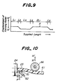
- the window molding member 50 has a pair of side portions 50a, 50b of the length L1, a pair of corner portions 50c, 50d of the length L2 and an upper portion 50e of the length L3, the relation between the displacement of the forming roller 66 in the directions M' and N' and the supplied length of the core element 57 is as shown in Fig. 9.
- the forming roller 66 assumes its uppermost position and is out of contact with the surface of the lip section 61, while the cutter member 65 extends slightly into the projection 62 of the lip section 61 so that a controlled small amount of material is removed from the projection 62, as shown in Fig. 8.
- the servomotor 69 is actuated in the normal direction, displacing the forming roller 66 in the direction N'.
- the forming roller 66 comes into contact with the lip section 61 to deflect this section counterclockwisely with reference to the leg section 58, from an initial angular position shown in Fig. 7 to a deflected angular position shown in Fig. 5.
- Such a deflection of the lip section 61 causes the projection 62 to be lowered, as seen in Figs. 5 to 7, whereas the cutter member 65 assumes a fixed position with reference to the extrusion die 24, so that the projection 62 is subjected to the removal of the material with a gradually increasing depth.
- the servomotor 69 is stopped so that the forming roller 66 is maintained in its lowermost position.
- the resultant maximum deflection of the lip section 61 corresponds to the removal of the material from the projection 62 with the maximum depth.
- the forming roller 66 is maintained in this position until the detector of the measuring station detects completion of the supply of the length L3 of the core element 57.
- the servomotor 69 is then actuated in the reverse direction to displace the forming roller 66 toward the uppermost position.
- the lip section 61 begins to restore into the initial angular position shown in Fig. 8, and the projection 62 thus moves upwardly with reference to the cutter member 65, so that the cutter member 65 removes material from the projection 62 with a gradually decreasing depth.
- the servomotor 69 is stopped as the detector of the measuring station detects completion of the length L2 of the core element 57, and the forming roller 66 is maintained in its uppermost position shown in Fig. 7, for a new cycle of operation, until twice the length L1 of the core element 57 is supplied to the extrusion die 24.
- the extruded body 25 is then cooled and solidified, and is further supplied to the second cutting station, like the station 30 shown in Fig. 2, where it is cut into the predetermined length of the window molding member 50 at a point X shown in Fig. 9, which is at the center of the two side portions.
- FIG. 10 A modification to the above-mentioned embodiment is shown in Fig. 10, in which the cutter member 70 is arranged on or adjacent to the extrusion die 24 and is movable in the directions P' and Q', synchronously with the movement of the forming roller 66 in the directions M' and N'.
- the depth with which material is removed from the projection 62 is varied by the movement of the cutter member 70, while the forming roller 66 serves to deform the lip section 61 while it is still hot and soft.
- the window molding member 50 shown in Figs. 3 and 4 can be produced in a continuous manner as described above.
- a strip-like retainer member 71 with a plurality of retaining fins is adhered to the side and upper webs 52a of the automobile body panel 52.
- the rubber dam 53 is preliminary secured onto the periphery of the rear surface of the window plate 51 which is then applied with adhesive material 53.
- the window plate 51 is then temporarily supported on the flange 52b of the body panel 52, and the leg section 58 of the molding member 50 is inserted, before the adhesive material 53 hardens, into the gap 59 between the body panel 52 and the window plate 51, engaging fins 58a and 58b of the leg section 58 with the retaining fins of the retainer member 71 and the rear edge of the window plate 51, respectively.
- the present invention provides a novel method of producing elongate molding members for automobiles, whereby the longitudinally variable cross-sectional shape of the molding member can be readily obtained essentially based on extrusion molding technology, simply by removing a controlled amount of the synthetic resin material from a predetermined location of the continuous body after it has been extruded, and by subsequently cutting the continuous body into a predetermined length of the molding member.
- the present invention is advantageous in that all the process steps can be carried out continuously, as contrasted with the conventional injection molding method, so that it is possible to produce the molding member with the desired, longitudinally variable cross-sectional shape, by means of a compact arrangement of the facility, and with a markedly improved productivity.
Landscapes
- Engineering & Computer Science (AREA)
- Mechanical Engineering (AREA)
- Life Sciences & Earth Sciences (AREA)
- Forests & Forestry (AREA)
- Manufacturing & Machinery (AREA)
- Extrusion Moulding Of Plastics Or The Like (AREA)
Claims (5)
- Procédé pour fabriquer un élément profilé (2, 3, 50), par exemple pour une vitre avant ou une vitre arrière d'une automobile (1) qui comprend, vue en coupe, un corps principal (50) adapté à recouvrir un interstice formé entre un panneau de vitre (61) et un panneau (52) de la carrosserie de l'automobile, une section de lèvre (61) faisant saillie dudit corps principal (50) et adaptée à recouvrir la périphérie externe dudit panneau de vitre (51) l'élément profilé étant formé au moins en partie en résine synthétique et le procédé comprenant les étapes consistant à extruder le matériau en résine synthétique en un corps continu allongé (25) de section sensiblement constante sur toute sa longueur; et à éliminer d'un emplacement prédéterminé dudit corps continu (25) une quantité contrôlée du matériau en résine synthétique, en synchronisme avec l'extrusion du matériau en résine synthétique, de manière que la section dudit corps continu (25) varie dans sa direction longitudinale caractérisé en ce que ledit corps principal (50) comprend en outre une section de nervure (62) faisant saillie de la section de lèvre (61) pour empêcher le passage de l'eau au-delà de ladite section de nervure (62), et en ce que ladite quantité contrôlée de matériau en résine synthétique est éliminée de la portion dudit corps continu (25) qui correspond à ladite section de nervure (62) dudit élément profilé en infléchissant la section de lèvre (61) du corps principal (50) le long de la partie depuis laquelle la quantité contrôlée doit être retirée de manière que la section de nervure (62) vienne en engagement avec des moyens (65) par lesquels la quantité contrôlée est éliminée, et en ce que le corps continu (25) est ensuite découpé selon des longueurs prédéterminées.
- Procédé selon la revendication 1, dans lequel ladite quantité contrôlée de matériau en résine synthétique est retirée du corps continu (25) après que le corps continu (25) a été extrudé, alors qu'il est toujours à l'état chaud et mou.
- Procédé selon la revendication 1 ou 2, dans lequel ledit corps continu (25) est formé par l'alimentation continue d'un élément de coeur (4, 58) vers une matrice d'extrusion (24) par laquelle ledit matériau en résine synthétique est extrudé avec ledit élément de coeur (4, 58), et dans lequel ladite quantité contrôlée de matériau en résine synthétique est retirée du corps continu (25) en accord avec la longueur fournie dudit élément de coeur.
- Procédé selon la revendication 1, 2 ou 3, dans lequel ledit élément profilé est un élément profilé de pare-brise (2) d'une automobile (1) et comprend une portion supérieure (2b) adaptée a s'étendre le long de la jonction entre le bord supérieur dudit panneau de pare-brise et un panneau de toit de l'automobile (1), et dans lequel ladite quantité contrôlée de matériau en résine synthétique est retirée de la portion dudit corps continu (25) qui forme ladite portion supérieure (2b) dudit élément profilé.
- Procédé selon la revendication 1, 2 ou 3, dans lequel ledit élément profilé est un élément profilé pour vitre arrière d'une automobile, et comprend des portions latérales qui s'étendent le long de la jonction entre les bords latéraux dudit panneau de vitre et tes montants arrière de l'automobile, et dans lequel ladite quantité contrôlée de matériau en résine synthétique est retirée des portions dudit corps continu qui forment les portions latérales dudit élément profilé.
Priority Applications (2)
| Application Number | Priority Date | Filing Date | Title |
|---|---|---|---|
| EP92119915A EP0541130B1 (fr) | 1988-01-29 | 1988-04-15 | Elément moulé et son procédé de fabrication |
| EP92119916A EP0540061B1 (fr) | 1988-01-29 | 1988-04-15 | Elément moulé et son procédé de fabrication |
Applications Claiming Priority (2)
| Application Number | Priority Date | Filing Date | Title |
|---|---|---|---|
| JP63019289A JPH01195032A (ja) | 1988-01-29 | 1988-01-29 | ウインドウモールディングの製造方法 |
| JP19289/88 | 1988-01-29 |
Related Child Applications (2)
| Application Number | Title | Priority Date | Filing Date |
|---|---|---|---|
| EP92119916.2 Division-Into | 1992-11-23 | ||
| EP92119915.4 Division-Into | 1992-11-23 |
Publications (2)
| Publication Number | Publication Date |
|---|---|
| EP0325828A1 EP0325828A1 (fr) | 1989-08-02 |
| EP0325828B1 true EP0325828B1 (fr) | 1993-06-16 |
Family
ID=11995280
Family Applications (3)
| Application Number | Title | Priority Date | Filing Date |
|---|---|---|---|
| EP92119915A Expired - Lifetime EP0541130B1 (fr) | 1988-01-29 | 1988-04-15 | Elément moulé et son procédé de fabrication |
| EP88303433A Expired - Lifetime EP0325828B1 (fr) | 1988-01-29 | 1988-04-15 | Procédé pour fabriquer des éléments profilés |
| EP92119916A Expired - Lifetime EP0540061B1 (fr) | 1988-01-29 | 1988-04-15 | Elément moulé et son procédé de fabrication |
Family Applications Before (1)
| Application Number | Title | Priority Date | Filing Date |
|---|---|---|---|
| EP92119915A Expired - Lifetime EP0541130B1 (fr) | 1988-01-29 | 1988-04-15 | Elément moulé et son procédé de fabrication |
Family Applications After (1)
| Application Number | Title | Priority Date | Filing Date |
|---|---|---|---|
| EP92119916A Expired - Lifetime EP0540061B1 (fr) | 1988-01-29 | 1988-04-15 | Elément moulé et son procédé de fabrication |
Country Status (7)
| Country | Link |
|---|---|
| US (2) | US4865796A (fr) |
| EP (3) | EP0541130B1 (fr) |
| JP (1) | JPH01195032A (fr) |
| KR (1) | KR940000620B1 (fr) |
| AU (1) | AU593991B2 (fr) |
| CA (1) | CA1323163C (fr) |
| DE (3) | DE3855847T2 (fr) |
Families Citing this family (71)
| Publication number | Priority date | Publication date | Assignee | Title |
|---|---|---|---|---|
| JPS63141849A (ja) * | 1986-12-01 | 1988-06-14 | Hashimoto Forming Co Ltd | モ−ルデイングおよびその製造方法 |
| JPH0628910B2 (ja) * | 1987-09-29 | 1994-04-20 | 橋本フォーミング工業株式会社 | ウインドウモールディングの製造方法 |
| JPH0615292B2 (ja) * | 1987-11-30 | 1994-03-02 | 橋本フォーミング工業株式会社 | ウインドウモールディングおよびその製造方法 |
| JPH0640491Y2 (ja) * | 1988-03-28 | 1994-10-26 | 株式会社ニフコ | 自動車の窓ガラス用周縁モール |
| DE3819916C2 (de) * | 1988-06-11 | 1996-12-19 | Erfurt Umformtechnik Gmbh | Verfahren zur Dosierung der Materialmenge bei der Herstellung von Formteilen aus härtbaren Formmassen |
| CA2002768C (fr) * | 1988-11-10 | 1997-10-07 | Tatsuya Tamura | Methode de fabrication de fenetres pour vehicules automobiles |
| JPH0278408U (fr) * | 1988-12-06 | 1990-06-15 | ||
| US5009947A (en) * | 1989-04-28 | 1991-04-23 | Schlegel Corporation | Elastomeric strip and method of manufacture |
| US5112547A (en) * | 1989-08-07 | 1992-05-12 | Hashimoto Forming Industry Co., Ltd. | Method of making an elongate article |
| US5203946A (en) * | 1989-09-25 | 1993-04-20 | Hashimoto Forming Industry Co., Ltd. | Method of, and apparatus for manufacturing elongate plastic articles |
| US5061335A (en) * | 1989-09-25 | 1991-10-29 | Hashimoto Forming Industry Co., Ltd. | Method of, and apparatus for manufacturing elongate plastic articles |
| JP2823601B2 (ja) * | 1989-09-25 | 1998-11-11 | 株式会社イノアックコーポレーション | ウインドウモール |
| US5233805A (en) * | 1989-10-14 | 1993-08-10 | Tokai Kogyo Kabushiki Kaisha | Molding for automotive front glass and molding apparatus |
| JP3081211B2 (ja) * | 1989-10-27 | 2000-08-28 | 東海興業株式会社 | 自動車のフロントガラス用モールディング、及びその製造方法 |
| JPH03143730A (ja) * | 1989-10-27 | 1991-06-19 | Tokai Kogyo Kk | 自動車のフロントガラス用モールディング、及びその成形装置 |
| JPH0745379Y2 (ja) * | 1989-11-22 | 1995-10-18 | 東海興業株式会社 | 自動車のウインドガラスのシール装置 |
| DE4025166C2 (de) * | 1990-08-08 | 1999-01-14 | Siv Deutschland Gmbh | Verfahren zum Herstellen einer Endlos-Polyurethanraupe |
| US5174623A (en) * | 1990-09-06 | 1992-12-29 | Tokai Kogyo Kabushiki Kaisha | Automobile windshield molding |
| US5190338A (en) * | 1990-09-06 | 1993-03-02 | Tokai Kogyo Kabushiki Kaisha | Automobile windshield molding and method of producing the same |
| USRE37737E1 (en) | 1990-09-06 | 2002-06-11 | Tokai Kogyo Kabushiki Kaisha | Automobile windshield molding and method of producing the same |
| US5656223A (en) * | 1991-07-25 | 1997-08-12 | Tokai Kogyo Kabushiki Kaisha | Windshield molding for vehicles and the production method thereof |
| US6095586A (en) * | 1990-10-23 | 2000-08-01 | Tokai Kogyo Kabushiki Kaisha | Automobile windshield molding and the method of producing the same |
| DE69122211T2 (de) * | 1990-10-23 | 1997-04-24 | Tokai Kogyo Co Ltd | Formteil für Kraftfahrzeugwindschutzscheibe und Vorrichtung zu dessen Herstellung |
| US6196615B1 (en) | 1990-10-23 | 2001-03-06 | Tokai Kogyo Kabushiki Kaisha | Automobile windshield molding and the method of producing the same |
| US5281291A (en) * | 1990-10-24 | 1994-01-25 | Tokai Kogyo Kabushiki Kaisha | Molding and method of producing the same |
| US5229054A (en) * | 1990-11-30 | 1993-07-20 | Tokai Kogyo Kabushiki Kaisha | Method of manufacturing automobile windshield molding |
| US5492387A (en) * | 1991-03-15 | 1996-02-20 | Tokai Kogyo Kabushiki Kaisha | Automobile windshield molding |
| JP2600511B2 (ja) * | 1991-03-29 | 1997-04-16 | 橋本フォーミング工業株式会社 | ウインドウモールディングおよびその製造方法 |
| US5257450A (en) * | 1991-03-29 | 1993-11-02 | Hashimoto Forming Industry Co., Ltd. | Automobile windshield molding member and method of manufacturing the same |
| JP3150361B2 (ja) * | 1991-05-31 | 2001-03-26 | 東海興業株式会社 | 車両用モールディング及びその製造方法 |
| US5507992A (en) * | 1991-07-25 | 1996-04-16 | Tokai Kogyo Kabushiki Kaisha | Windshield molding for vehicles and the production method thereof |
| US5350211A (en) * | 1991-09-30 | 1994-09-27 | Tokai Kogyo Kabushiki Kaisha | Windshield molding for vehicles and the production method thereof |
| US5266021A (en) * | 1991-10-10 | 1993-11-30 | Jacobson Theodore L | Apparatus for continuous forming of complex molded shapes |
| US5149478A (en) * | 1991-11-18 | 1992-09-22 | The Standard Products Company | Forming decorative trim strips from continuous extrusions |
| US5395563A (en) * | 1992-02-05 | 1995-03-07 | Toyoda Gosei Co., Ltd. | Manufacturing method and apparatus for forming an elongate body having thickness change |
| JP3072941B2 (ja) * | 1992-06-26 | 2000-08-07 | 東海興業株式会社 | 自動車用モールディングの製造方法 |
| JP2598973Y2 (ja) * | 1992-08-18 | 1999-08-23 | 東海興業株式会社 | 自動車用ウインドモールディング |
| JPH06144003A (ja) * | 1992-11-04 | 1994-05-24 | Nifco Inc | フロントガラス用モールディング |
| GB9304411D0 (en) * | 1993-03-04 | 1993-04-21 | Silent Channel Prod Ltd | Vehicle window frame |
| DE59403686D1 (de) * | 1993-03-11 | 1997-09-18 | Henniges Elastomer Kunststoff | Karosseriefenster |
| DE4313194C1 (de) * | 1993-04-22 | 1994-04-07 | Metzeler Automotive Profiles | Verfahren zur Herstellung von endlichen Profilsträngen und Vorrichtung zur Durchführung des Verfahrens |
| US5447670A (en) * | 1993-04-28 | 1995-09-05 | Toyoda Gosei Co., Ltd. | Method of and apparatus for forming weather strip by extrusion |
| US5360251A (en) * | 1993-11-09 | 1994-11-01 | Nifco, Inc. | Flush mount molding member |
| US6007319A (en) * | 1993-11-30 | 1999-12-28 | Continuous Molding, Inc. | Continuous forming of complex molded shapes |
| US5529650A (en) * | 1994-05-24 | 1996-06-25 | Green Tokai Co., Inc. | Method of making flocked, vehicle molding |
| JP3019729B2 (ja) * | 1994-09-22 | 2000-03-13 | 豊田合成株式会社 | ウエザストリップの押出成形方法及び押出成形装置 |
| GB9424188D0 (en) * | 1994-11-30 | 1995-01-18 | Heywood Williams Plastics Ltd | Window security |
| JPH0911739A (ja) * | 1995-06-29 | 1997-01-14 | Toyoda Gosei Co Ltd | 自動車用ウインドモール |
| KR0145834B1 (ko) * | 1995-10-06 | 1998-08-17 | 전성원 | 루프패널의 낙수방지용 모울드 |
| CA2216783C (fr) * | 1996-01-30 | 2004-11-23 | Hashimoto Forming Industry Co., Ltd. | Element composite allonge dont la section transversale varie longitudinalement, procede et appareil pour sa fabrication |
| JP3206439B2 (ja) * | 1996-06-28 | 2001-09-10 | 東海興業株式会社 | モールディングの製造方法及び装置 |
| US5874034A (en) * | 1997-04-14 | 1999-02-23 | Xerox Corporation | Swell reducing extrusion die |
| US5964979A (en) | 1997-08-15 | 1999-10-12 | 3M Innovative Properties Company | Sealing method and article |
| GB2334990A (en) * | 1998-03-03 | 1999-09-08 | Draftex Ind Ltd | A sealing strip for a sunroof comprising a water-directing lip along part of its length |
| US6224145B1 (en) | 1998-10-30 | 2001-05-01 | Inoac Corporation | Roof molding for an automobile and method of trimming the same |
| US6513854B2 (en) * | 2001-02-15 | 2003-02-04 | Centre Luxembourgeois De Recherches Pour Le Verre Et La Ceramique S.A. (C.R.V.C.) | Method of applying extruded profile to corners of a window glazing |
| US6854784B2 (en) * | 2002-05-22 | 2005-02-15 | Honda Giken Kogyo Kabushiki Kaisha | Automobile drip molding, mounting construction thereof and method of mounting |
| JP3866157B2 (ja) * | 2002-05-22 | 2007-01-10 | 本田技研工業株式会社 | 自動車用ドリップモール |
| FR2854360B1 (fr) * | 2003-04-29 | 2006-06-02 | Silvatrim Sa | Procede de fabrication d'un enjoliveur presentant un corps extrude et une trappe de meme aspect |
| WO2004108458A1 (fr) * | 2003-06-04 | 2004-12-16 | Decoma International Inc. | Rail de glissiere de guidage de glace en plastique rigide |
| FR2864919B1 (fr) * | 2004-01-14 | 2006-03-24 | Hutchinson | Cellule de pose dynamique en continu d'un joint d'etancheite adhesive sur un support de reception. |
| DE102004050861B4 (de) * | 2004-10-18 | 2009-10-08 | Webasto Ag | Formwerkzeug und Verfahren zur Herstellung einer mit Kunststoff umgossenen, umspritzten oder umschäumten Platte |
| US8096601B2 (en) * | 2005-06-22 | 2012-01-17 | Magna Car Top Systems Gmbh | Rear window in a rear roof section of an openable roof vehicle |
| US8109812B2 (en) * | 2007-12-14 | 2012-02-07 | Toyota Motor Engineering & Manufacturing North America, Inc. | Motor vehicle instrument panel assembly having a conduit with a gasket support lip |
| US9174519B2 (en) | 2011-10-18 | 2015-11-03 | Henniges Automotive Sealing Systems North America Inc. | Weatherstrip assembly having a variable length shim |
| US9127457B2 (en) * | 2012-07-10 | 2015-09-08 | King Saud University | Machine for deforming and cutting plastic strips for enhancing concrete |
| SG11201600114TA (en) * | 2013-07-08 | 2016-02-26 | 3M Innovative Properties Co | Installation tools, systems, and methods for flexible profile moldings, such as window film adhesive attachment articles |
| FR3018251B1 (fr) * | 2014-03-07 | 2017-09-15 | Renault Sas | Deflecteur de vehicule automobile, notamment pour pare-brise |
| JP6268081B2 (ja) * | 2014-12-05 | 2018-01-24 | 片山工業株式会社 | モールディング |
| WO2018091993A1 (fr) * | 2016-11-17 | 2018-05-24 | Milan Conception Inc. | Procédé et appareil de coupe destinés à couper des profils d'ébauche |
| CN106944942B (zh) * | 2017-04-28 | 2019-04-05 | 赵永兴 | 一种管子台虎钳 |
Family Cites Families (42)
| Publication number | Priority date | Publication date | Assignee | Title |
|---|---|---|---|---|
| DE1235164B (de) * | 1967-02-23 | Porsche Kg | Profilleiste zur Einfassung bzw. Halterung von Scheiben, insbesondere Windschutzscheiben von Kraftfahrzeugen | |
| US2126151A (en) * | 1936-08-31 | 1938-08-09 | Monsanto Chemicals | Process of flocculation |
| US2610714A (en) * | 1951-11-28 | 1952-09-16 | Detroit Macoid Corp | Sealing strip |
| US2763346A (en) * | 1953-06-09 | 1956-09-18 | Gen Motors Corp | Connector strip |
| CH363794A (de) * | 1957-08-09 | 1962-08-15 | Basf Ag | Verfahren und einrichtung zur Herstellung von stranggepressten Profilstäben aus thermoplastischen Kunststoffen |
| DE1630375C3 (de) * | 1967-10-20 | 1979-11-29 | Daimler-Benz Ag, 7000 Stuttgart | Einfassungsleiste für seitlich zurückgewölbte Windschutzscheiben von Kraftfahrzeugen |
| NL160422C (nl) * | 1974-05-21 | 1979-10-15 | Philips Nv | Werkwijze voor de vervaardiging van een coaxiaalkabel en coaxiaalkabel verkregen met deze werkwijze. |
| JPS50158659A (fr) * | 1974-06-14 | 1975-12-22 | ||
| DE2617123A1 (de) * | 1976-04-17 | 1977-10-27 | Huebner Gummi & Kunststoff | Verfahren zur herstellung eines strangfoermigen profils, vorrichtung zur durchfuehrung des verfahrens und strangfoermiges, gemaess dem verfahren hergestelltes profil |
| JPS5411977A (en) * | 1977-06-30 | 1979-01-29 | Inoue Gomu Kogyo Kk | Manufacture of synthetic resin lace |
| US4256685A (en) * | 1977-07-05 | 1981-03-17 | W. James Kemerer | Variable profile extrusion method |
| JPS5756214A (en) * | 1980-09-19 | 1982-04-03 | Hashimoto Forming Co Ltd | Method and device for terminal cutting of synthetic resin molding |
| JPS57109913U (fr) * | 1980-12-26 | 1982-07-07 | ||
| DE3107218A1 (de) * | 1981-02-26 | 1982-09-02 | Dr.Ing.H.C. F. Porsche Ag, 7000 Stuttgart | Regenrinne fuer ein fahrzeug, insbesondere kraftfahrzeug |
| DE3148212A1 (de) * | 1981-12-05 | 1983-06-09 | Continental Gummi-Werke Ag, 3000 Hannover | Strangpresse |
| DE3224906C2 (de) * | 1982-07-03 | 1985-09-12 | Continental Gummi-Werke Ag, 3000 Hannover | Vorrichtung zum Herstellen von Profilsträngen aus elastomeren Werkstoffen |
| JPS5970528A (ja) * | 1982-10-14 | 1984-04-21 | Nishikawa Gomme Kogyo Kk | 押出成形方法及び同装置 |
| JPS5978837A (ja) * | 1982-10-28 | 1984-05-07 | Kinugawa Rubber Ind Co Ltd | 自動車用ウエザ−ストリツプの成形方法 |
| JPS5983519U (ja) * | 1982-11-30 | 1984-06-06 | 西川ゴム工業株式会社 | 押出成形装置 |
| IT1157134B (it) * | 1982-12-10 | 1987-02-11 | Saiag Spa | Procedimento ed apparecchiatura per realizzare mediante estrusione continua un trafilato in particolare una guarnizione di tenuta per carrozzerie di autoveicoli presentante successivi tratti di lunghezze predeterminate aventi ciascuno una rispettiva sezione prestabilita e trafilato ottenuto con tale procedimento |
| IT1161480B (it) * | 1983-02-03 | 1987-03-18 | Saiag Spa | Dispositivo per modificare durante l'estrusione l'inclinazione o l'orientamento di una aletta longitudinale di una guarnizione estrusa di tenuta per autoveicoli e guarnizione ottenuta con tale dispositivo |
| IT1165544B (it) * | 1983-02-17 | 1987-04-22 | Saiag Spa | Apparecchiatura per sincronizzare le variazioni di sezione di un trafilato in particolare di una guarnizione di tenuta per carrozzerie di autoveicoli con l'avanzamento del trafilato in una macchina per estrusione e macchina per estrusione e macchina per estrusione comprendente l'apparecchiatura |
| JPS60104322A (ja) * | 1983-11-11 | 1985-06-08 | Shiraki Kinzoku Kogyo Kk | ベルトモ−ルデイングとその製造方法 |
| DE3427346A1 (de) * | 1984-07-25 | 1986-01-30 | Continental Gummi-Werke Ag, 3000 Hannover | Verfahren zum herstellen von dichtungs- und/oder klemmprofilleisten |
| JPS61135824A (ja) * | 1984-12-05 | 1986-06-23 | Kinugawa Rubber Ind Co Ltd | 車両用ウインドモ−ル |
| JPS61167521A (ja) * | 1985-01-21 | 1986-07-29 | Toyoda Gosei Co Ltd | ウエザ−ストリツプの製造方法 |
| JPS61202917A (ja) * | 1985-03-05 | 1986-09-08 | Kinugawa Rubber Ind Co Ltd | 車両用フラツシユマウントモ−ル |
| IT1183795B (it) * | 1985-04-03 | 1987-10-22 | Saiag Spa | Procedimento e dispositivo per la fabbricazione di una guarnizione per autoveicoli e guarnizione ottenuta con il procedimento |
| JPS62178422A (ja) * | 1986-01-31 | 1987-08-05 | Hashimoto Forming Co Ltd | ウインドウモ−ルデイング |
| DE3608223A1 (de) * | 1986-03-12 | 1987-10-15 | Huehoco Bandeisen Und Metallwa | Traegerband aus metall fuer profilleisten mit mantel und zier- oder funktionsstreifen |
| JPH0626922B2 (ja) * | 1986-03-15 | 1994-04-13 | 株式会社ニフコ | 自動車の窓ガラス用周縁モ−ル |
| JPH069929B2 (ja) * | 1986-03-31 | 1994-02-09 | 橋本フォーミング工業株式会社 | ウインドウモ−ルデイング |
| JPH0517290Y2 (fr) * | 1986-05-30 | 1993-05-10 | ||
| JPH0645299B2 (ja) * | 1986-05-30 | 1994-06-15 | 橋本フオ−ミング工業株式会社 | ウインドウモ−ルデイングおよびその製造方法 |
| JPH0729547B2 (ja) * | 1986-06-30 | 1995-04-05 | 橋本フオ−ミング工業株式会社 | 車両用ウインドウ |
| JPH0698895B2 (ja) * | 1986-06-30 | 1994-12-07 | 橋本フオ−ミング工業株式会社 | ウインドウモ−ルデイングの製造方法 |
| JP2821739B2 (ja) * | 1986-06-30 | 1998-11-05 | 橋本フォーミング工業 株式会社 | ウインドウモールデイング |
| US4757660A (en) * | 1986-12-04 | 1988-07-19 | Tokiwa Chemical Industries Co., Ltd. | Front glass mouldings |
| US4757659A (en) * | 1986-12-04 | 1988-07-19 | Tokiwa Chemical Industries Co., Ltd. | Front glass mouldings |
| US4833847A (en) * | 1987-03-12 | 1989-05-30 | Toyoda Gosei Co., Ltd. | Flush mounting molding |
| JPH0636977Y2 (ja) * | 1988-01-30 | 1994-09-28 | 株式会社ニフコ | 接着式ウインドのモール装着装置 |
| JPH06338023A (ja) * | 1993-05-28 | 1994-12-06 | Sony Corp | 磁気ヘッド |
-
1988
- 1988-01-29 JP JP63019289A patent/JPH01195032A/ja active Granted
- 1988-04-13 US US07/180,893 patent/US4865796A/en not_active Expired - Lifetime
- 1988-04-15 DE DE3855847T patent/DE3855847T2/de not_active Expired - Fee Related
- 1988-04-15 DE DE88303433T patent/DE3881860T2/de not_active Expired - Fee Related
- 1988-04-15 EP EP92119915A patent/EP0541130B1/fr not_active Expired - Lifetime
- 1988-04-15 AU AU14692/88A patent/AU593991B2/en not_active Ceased
- 1988-04-15 DE DE3854946T patent/DE3854946T2/de not_active Expired - Fee Related
- 1988-04-15 EP EP88303433A patent/EP0325828B1/fr not_active Expired - Lifetime
- 1988-04-15 EP EP92119916A patent/EP0540061B1/fr not_active Expired - Lifetime
- 1988-04-18 KR KR1019880004408A patent/KR940000620B1/ko not_active Expired - Lifetime
- 1988-04-19 CA CA564516A patent/CA1323163C/fr not_active Expired - Fee Related
-
1989
- 1989-07-13 US US07/379,283 patent/US5074610A/en not_active Expired - Lifetime
Also Published As
| Publication number | Publication date |
|---|---|
| KR890011692A (ko) | 1989-08-22 |
| EP0541130B1 (fr) | 1997-03-26 |
| DE3881860T2 (de) | 1993-09-30 |
| EP0325828A1 (fr) | 1989-08-02 |
| KR940000620B1 (ko) | 1994-01-26 |
| JPH01195032A (ja) | 1989-08-04 |
| DE3854946T2 (de) | 1996-05-30 |
| AU593991B2 (en) | 1990-02-22 |
| DE3854946D1 (de) | 1996-03-07 |
| EP0540061B1 (fr) | 1996-01-24 |
| US5074610A (en) | 1991-12-24 |
| JPH0564584B2 (fr) | 1993-09-14 |
| AU1469288A (en) | 1989-08-03 |
| CA1323163C (fr) | 1993-10-19 |
| EP0541130A1 (fr) | 1993-05-12 |
| EP0540061A1 (fr) | 1993-05-05 |
| DE3855847T2 (de) | 1997-11-27 |
| DE3881860D1 (de) | 1993-07-22 |
| US4865796A (en) | 1989-09-12 |
| DE3855847D1 (de) | 1997-04-30 |
Similar Documents
| Publication | Publication Date | Title |
|---|---|---|
| EP0541130B1 (fr) | Elément moulé et son procédé de fabrication | |
| US5061335A (en) | Method of, and apparatus for manufacturing elongate plastic articles | |
| EP0310262B1 (fr) | Joint d'étanchéité pour fenêtres et méthode pour sa fabrication | |
| US5028460A (en) | Molding member and method of producing same | |
| EP0319262B1 (fr) | Moulure de fenêtre et méthode de fabrication | |
| EP0412217B1 (fr) | Procédé et dispositif pour la fabrication d'articles allongés | |
| EP0541824B1 (fr) | Moulure de fenetre pour vehicule et procede de production | |
| US5104173A (en) | Window molding member for automobiles, and method of manufacturing the same | |
| US5193875A (en) | Automobile windshield molding member and method of manufacturing the same | |
| US5310236A (en) | Molding member for automobile window plate | |
| JPH06459B2 (ja) | ウインドモールディングおよびその製造方法 | |
| US5203946A (en) | Method of, and apparatus for manufacturing elongate plastic articles | |
| EP0423407B1 (fr) | Eléments de moulure de fenêtre pour véhicules automobiles et procédé de fabrication des mêmes | |
| US5257450A (en) | Automobile windshield molding member and method of manufacturing the same | |
| JPS62280019A (ja) | ウインドウモ−ルデイングの製造方法 | |
| EP0419738B1 (fr) | Procédé et dispositif pour la fabrication d'articles allongés | |
| JPS63242526A (ja) | モ−ルデイングの製造方法 | |
| JP3010939B2 (ja) | ウインドウモールディング | |
| JPH07195478A (ja) | 長尺装飾材および製造方法 | |
| JPH02258445A (ja) | 異色部分を有する長尺な装飾モールディングの製造方法 | |
| JPH0717021B2 (ja) | 車両用樹脂成形品の製造方法 | |
| JPH08309822A (ja) | 車両用モールおよびモール付き板状体の製造方法、並びにモール成形装置 |
Legal Events
| Date | Code | Title | Description |
|---|---|---|---|
| PUAI | Public reference made under article 153(3) epc to a published international application that has entered the european phase |
Free format text: ORIGINAL CODE: 0009012 |
|
| AK | Designated contracting states |
Kind code of ref document: A1 Designated state(s): DE FR GB IT |
|
| 17P | Request for examination filed |
Effective date: 19900126 |
|
| 17Q | First examination report despatched |
Effective date: 19901001 |
|
| GRAA | (expected) grant |
Free format text: ORIGINAL CODE: 0009210 |
|
| AK | Designated contracting states |
Kind code of ref document: B1 Designated state(s): DE FR GB IT |
|
| XX | Miscellaneous (additional remarks) |
Free format text: TEILANMELDUNG 92119915.4 EINGEREICHT AM 15/04/88. |
|
| REF | Corresponds to: |
Ref document number: 3881860 Country of ref document: DE Date of ref document: 19930722 |
|
| ET | Fr: translation filed | ||
| ITF | It: translation for a ep patent filed | ||
| PLBE | No opposition filed within time limit |
Free format text: ORIGINAL CODE: 0009261 |
|
| STAA | Information on the status of an ep patent application or granted ep patent |
Free format text: STATUS: NO OPPOSITION FILED WITHIN TIME LIMIT |
|
| 26N | No opposition filed | ||
| REG | Reference to a national code |
Ref country code: GB Ref legal event code: IF02 |
|
| PGFP | Annual fee paid to national office [announced via postgrant information from national office to epo] |
Ref country code: FR Payment date: 20060410 Year of fee payment: 19 |
|
| PGFP | Annual fee paid to national office [announced via postgrant information from national office to epo] |
Ref country code: GB Payment date: 20060412 Year of fee payment: 19 |
|
| PGFP | Annual fee paid to national office [announced via postgrant information from national office to epo] |
Ref country code: DE Payment date: 20060413 Year of fee payment: 19 |
|
| PGFP | Annual fee paid to national office [announced via postgrant information from national office to epo] |
Ref country code: IT Payment date: 20060430 Year of fee payment: 19 |
|
| GBPC | Gb: european patent ceased through non-payment of renewal fee |
Effective date: 20070415 |
|
| PG25 | Lapsed in a contracting state [announced via postgrant information from national office to epo] |
Ref country code: DE Free format text: LAPSE BECAUSE OF NON-PAYMENT OF DUE FEES Effective date: 20071101 |
|
| PG25 | Lapsed in a contracting state [announced via postgrant information from national office to epo] |
Ref country code: GB Free format text: LAPSE BECAUSE OF NON-PAYMENT OF DUE FEES Effective date: 20070415 |
|
| PG25 | Lapsed in a contracting state [announced via postgrant information from national office to epo] |
Ref country code: FR Free format text: LAPSE BECAUSE OF NON-PAYMENT OF DUE FEES Effective date: 20070430 |
|
| PG25 | Lapsed in a contracting state [announced via postgrant information from national office to epo] |
Ref country code: IT Free format text: LAPSE BECAUSE OF NON-PAYMENT OF DUE FEES Effective date: 20070415 |