EP0351843A2 - Digitales adaptives Filter und Konvergenzverfahren darin - Google Patents
Digitales adaptives Filter und Konvergenzverfahren darin Download PDFInfo
- Publication number
- EP0351843A2 EP0351843A2 EP89113338A EP89113338A EP0351843A2 EP 0351843 A2 EP0351843 A2 EP 0351843A2 EP 89113338 A EP89113338 A EP 89113338A EP 89113338 A EP89113338 A EP 89113338A EP 0351843 A2 EP0351843 A2 EP 0351843A2
- Authority
- EP
- European Patent Office
- Prior art keywords
- unit
- echo
- main memory
- main
- output
- Prior art date
- Legal status (The legal status is an assumption and is not a legal conclusion. Google has not performed a legal analysis and makes no representation as to the accuracy of the status listed.)
- Withdrawn
Links
Images


Classifications
-
- H—ELECTRICITY
- H03—ELECTRONIC CIRCUITRY
- H03H—IMPEDANCE NETWORKS, e.g. RESONANT CIRCUITS; RESONATORS
- H03H21/00—Adaptive networks
- H03H21/0012—Digital adaptive filters
- H03H21/0043—Adaptive algorithms
Definitions
- the present invention relates to a digital adaptive filter and method of convergence therein. More particularly, it relates to an apparatus and a method for cancelling an echo component generated by a partial return of a transmission signal to a receiving side by a digital adaptive filter.
- a digital adaptive filter is used to cancel the echo component, and conventional digital adaptive filters are classified into two types, i.e., a look-up table type echo canceller and a transversal filter type echo canceller.
- a sequence of transmission signals is guided to a tap portion, and a pattern of the sequence of signals is used as an address when storing in a memory portion a sequence of pseudo echoes having an opposite polarity to an echo value. Accordingly, if an echo of the same address subsequently input, the echo is cancelled by the pseudo echo stored in the memory.
- the transversal filter type echo canceller employs a known transversal filter to converge the input signal.
- One tap coefficient is provided N pieces of input data, and according to the pattern of the tap coefficients and transmission symbols, pseudo echoes are generated to cancel echoes.
- the look-up table type echo canceller is advantageous for cancelling non-linear echo components, but the memory capacity thereof must be increased as the tap length of an echo becomes longer, thus causing a disadvantage in that an initial convergence time (a training time) may become longer. Particularly this disadvantage will be serious when multivalued codes are employed as transmission codes.
- the transversal filter type echo canceller is advantageous in that echoes having long tap lengths are cancelled within a short convergence time, but has a disadvantage in that non-linear echo components cannot be cancelled thereby.
- the above digital filters are rarely employed to cancel echoes containing non-linear components and having relatively long tap lengths.
- a memory division type digital filter having a look-up table memory divided into a main memory portion and a plurality of submemory portions was provided prior to the present invention
- the memory division type digital filter ebables a reduction of the memory capacity, as described in more detail later with reference to the drawings, but this arrangement incurs a division loss, i.e., an accumulated error appearing as a residual echo component.
- a first object of the present invention is to provide an apparatus and a method for cancelling an echo component in a memory division type digital filter having a reduced memory capacity and able to suppress any residual echo component is suppressed.
- a second object of the present invention is to provide an apparatus and a method for cancelling an echo component in a combination of a memory division digital filter and a transversal filter, in which a convergent algorithm is provided that can accurately carry out the initial convergence and adaptive control at a high speed.
- a digital adaptive filter for cancelling an echo component generated by a partial return of a transmission signal to a receiving side, comprising: a tap unit for sequentially shifting the transmission signal and outputting the shifted signal in parallel, the tap unit being divided into a main tap unit and at least one subtap unit; a main memory unit, operatively connected to the main tap unit; for storing a first echo replica which can be stored or read by using the parallel signal from the main tap unit as an address signal; at least one submemory unit, operatively connected to the at least one subtap unit for storing a second echo replica which can be stored or read by using the parallel signal from the subtap unit as an address signal; and an adding circuit, operatively connected to the main. memory unit and the submemory unit, for adding the first echo replica read from the main memory unit and the second echo replica read from the submemory unit.
- the second echo replica stored in the submemory unit having a precision greater than the precision of the first echo replica stored in the main memory unit.
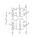
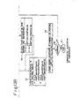
- Figure 1 is a block diagram showing a main part of a data transmission/reception unit wherein numeral II denotes a digital filter constituting an echo canceller; 12 a driver; 13: a hybrid circuit; and 14 an adder.
- a transmission signal S(k) from a transmission unit (not shown) is sent from the driver 12 to a transmission line such as a subscriber line, through the hybrid circuit 13, and reception data R(k) received through this transmission line is supplied to a receiver (not shown) through the hybrid circuit 13.
- the transmission data S(k) is partially returned to the receiving side through the hybrid circuit 13, thereby generating an echo component e(k), and this echo component e(k) is superposed on the reception data R(k).
- the digital filter 11 may have the arrangement exemplified in Fig. 2.
- the transmission data S(k) is input to a tap unit 21 including a shift register with a plurality of I-bit delay circuits (not shown) and is sequentially shifted, parallel output pulses are respectively output from the corresponding taps, and the resultant parallel signal serves as an address signal for a memory unit 22.
- the number of taps in the tap unit 21 corresponds to the characteristics of the echo component e(k), and the memory unit 22 includes a random access memory (RAM) and a controller.
- RAM random access memory
- the echo replica e(k) is written in the memory unit 22 in such a way that the residual echo component r(k), which is a difference between the echo component e(k) input through the hybrid circuit 13 and the echo replica e(k) read out from the memory unit 56, becomes zero, and when echo replicas e(k) are written to all addresses of the memory unit 22, the conversion process is completed.
- the echo replica e(k) corresponding to the pattern of the transmission data S(k) is read out and supplied to an adder 14.
- the adder 14 cancels an echo component contained in the reception data D(k) from the hybrid circuit, and the reception data R(k) having a zero residual echo component r(k) is transferred to the receiver.
- the number n of taps of the tap unit 21 corresponds to the characteristic of the echo replica e-(k), i.e., a length of received data influenced by the echo component e(k) returned from the hybrid circuit to the receiving side, and therefore, the capacity of the memory unit 22 is increased in proportion to 2", and the initial converging time is increased accordingly.
- the capacity of the memory unit 22 is increased in proportion to 4".
- the look-up table type echo canceler is advantageous for cancelling non-linear echo components, but as described above, memory capacity thereof must be increased as the tap length of an echo becomes longer, thus bringing a disadvantage in that an initial convergence time (a training time) may become longer. Particularly, this disadvantage is serious when multivalued codes are employed as transmission codes.
- the digital filter 11 shown in Fig. 1 is realized by a conventional transversal filter type echo canceler shown in Fig. 3 which employs a known transversal filter to converge the input signal.
- One tap coefficient is provided for N pieces of input data, and pseudo echoes ⁇ e(k) ⁇ are generated to cancel echoes, according to the pattern of the tap coefficients and transmission symbols.
- the conventional transversal filter type echo canceller is advantageous for efficiently cancelling echoes having long tap lengths within a short convergence time, but has a disadvantage in that non-linear echo components cannot be cancelled thereby.
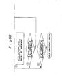
- a tap unit having n taps receiving the transmission signal S(k) is divided into a main tap unit 21a a having k taps and k 1-bit delay circuits (not shown) and a subtap unit 21 having (n-k) taps, and the memory unit is divided into a main memory unit 22a for receiving an address signal from the main tap unit 21a a and a submemory unit 21b for receiving an address signal from the subtap unit 21 b.
- An echo replica ECR1 from the main memory unit 22a and the reception data D(k) are added to an adder 14a, a residual echo component el of an output from the adder 14a and an echo replica ECR2 from the submemory unit 22b are applied to an adder 14b, and an output from the adder 14b serves as the received data R(k).
- the echo component corresponding to the tap number k of the main tap unit 21a is cancelled by the echo replica ECR1 from the main memory unit 22a, and the echo component corresponding to the tap number (n-k) of the subtap unit 21 b is cancelled by the echo replica ECR2 from the submemory unit 22b.
- convergence processing is performed using an algorithm which minimizes the residual echo components ⁇ 1 and ⁇ 2, and the echo replicas ECRI and ECR2 are respectively written in the main memory unit 22a and the submemory unit 22b.
- the capacity of the main memory unit 22a is proportional to 2 k and the capacity of the submemory unit 22b is proportional to 2 n-k . Therefore, the total capacity is proportional to 2 k + 2 n-k .
- the total capacity of the memory can be greatly reduced compared with the arrangment shown in Fig. 2, wherein the capacity of the memory unit 22 having n taps is proportional to 2".
- the memory division type arrangement can reduce the memory capacity as described above, this arrangement incurs a division loss, i.e., an accumulated error. More specifically, the echo components corresponding to the number n of all taps are not cancelled, and only the echo components corresponding to n and (n-k) divided taps are respectively cancelled.
- the convergence mode even when the echo replicas ECR1 and ECR2 corresponding to k and (n-k) of taps are very precisely written in the main memory unit 22a and the submemory unit 22b, respectively, if an error occurs in the echo replica ECRI, the residual echo component e1 is increased, and further, if an error occurs in the echo replica ECR2, the residual echo component e2 is increased.
- the total echo component is the sum of the residual echo components e1 and e2, and the least significant bit (LSB) error cannot be avoided in the echo replicas ECR1 and ECR2, respectively.
- the total error in the echo replica is the sum of the errors in the echo replicas ECR1 and ECR2. Therefore, in the worst case when the number of divisions in the memory division type digital filter is increased, the amount of the total error may be proportionally increased.
- the first object of the present invention is to provide a method and apparatus for cancelling an echo component in a memory division type digital filter in which the memory capacity is reduced and the residual echo component is suppressed.
- a look-up table memory is divided into a main memory unit 22a and a plurality of submemory units 22b-I to 22b-m, and further, a transversal filter unit 51 and an IIR (infinite length impulse response) filter unit 52 are added.
- the main memory unit 22a generates the large amplitude level portion containing a peak level of a pseudo echo
- the submemory units 22b-1 to 22b-m generate the relatively small echo levels following the large amplitude level portion of the pseudo echo
- the remaining portions are cancelled by the transversal filter unit 51 of "i" taps.
- the primary IIR filter portion 52 is disposed to cancel trailing echoes that monotonously attenuate.
- Another object of the invention is to provide a convergent algorithm that can accurately carry out the initial convergence and adaptive control at a high speed in an adaptive type digital filter shown in Fig. 5.
- Figure 6 is a block diagram of a memory division type digital filter according to an embodiment of the present invention, wherein an echo canceler 60 functions as a digital adaptive filter for cancelling echo components.
- the block diagram in Fig. 6 per se is substantially the same as the conventional block diagram shown in Fig. 4.
- the echo canceller 60 includes a main tap unit 61 for shifting transmitting data S(k) and for outputting same from a predetermined number of taps, a subtap unit 62, a I-bit delay circuit 63 for delaying the output shifted from the main tap unit 61, a main memory unit 64 for storing echo replicas, a submemory unit 65, and two adders 66 and 67.
- the delay circuit 63 is, in actual, the final stage delay circuit in the main tap unit 61. Therefore, in Fig. 4, the delay circuit 63 is not explicitly shown.
- the transmission data S(k) is transmitted through a hybrid circuit 68 to a transmission line 69, and furhter, is input to the main tap unit 61.
- the transmission data shifted in and serially output from the main tap unit 61 is then sent through the delay circuit 63 having a one bit delay to the subtap unit 62 wherein the data is shifted.
- the echo component X returned through the hybrid circuit 68 is applied to the adder 66, and through the adder 66 to the adder 67.
- An echo replica ECRI is read from the main memory unit 64 in accordance with an address signal from the main tap unit 61, and the read echo replica ECR1 is applied to the adder 66.
- An echo replica ECR2 is read from the submemory unit 65 in accordance with an address signal from the subtap unit 62, and the read echo replica ECR2 is applied to the adder 67.
- the adder 66 adds the echo component X and the echo replica ECR1, and the adder 67 adds the added result and the echo replica ECR2. Accordingly, receiving data R(k) in which the echo component X is cancelled is output from the echo cencel- ler 60.
- the stored echo replica has a greater precision than the echo replica stored in the main memory unit 64, according to the present invention, and due to this greater precision, the influence of the echo replica read from the submemory unit 65 upon the residual echo contained in the receiving signal from the adder 66 can be decreased as later described. Therefore, not only can the total memory capacity be reduced by dividing the tap unit into the main tap unit and the subtap unit, and by dividing the memory into the main memory unit and the submemory unit, respectively, but also the error can be decreased by the greater precision of the echo replica stored in the submemory.
- the greater precision of the echo replica is obtained by increasing the bit length of the echo replica ECR2 by, for example, one or two bits, in comparison with the bit length of the echo replica stored in the submemory unit in the conventional memory division type echo canceller.
- the increase of the bit length of the echo replica allows an increase of the memory capacity of the submemory but since the memory capacity of the submemory is much smaller than the memory capacity of the main memory, the increase of the memory capacity due to the increase of the bit length of the echo replica stored in the submemory is negligible in comparison with the memory capacity of the main memory.
- the maximum error in the echo replica ECRI output from the main memory unit 64 is al (when the number of bits in the echo replica is m, the maximum error is 1/2 m ), the amount of real echo to be cancelled in the main memory unit 64 is ECI, and the residual echo after cancelling the echo component by the echo replica ECRI is e1.
- the number of taps of the subtap unit 65 is n2
- the maximum error in the echo replica ECR2 output from the submemory 65 is a2
- the amount of real echo to be cancelled in the submemory unit 65 is EC1
- the residual echo after cancelling the echo component by the echo replica ECRI is e1.
- the residual echo having a maximum of al, is returned through the submemory unit 65 so that residual echo e has the following relationship:
- the final residual echo 6 may be, in the worst case, the sum of the maximum errors al and a2 of the echo replica ECRI in the main memory unit 64 and the echo replica ECR2 in the submemory unit 65, respectively, even when the echo replicas which are to be written in these memory units are correctly estimated. Therefore, by dividing the memory into a plurality of submemories, the errors are accumulated.
- the accumulated error due to the memory division can be suppressed to a negligible amount by greatly reducing the maximum error a2 of the echo replica in the submemory unit 65, in comparison with the maximum error a1 of the echo replica in the main memory unit 64. Namely, when the maximum error a2 is negligible, al + a2 is nearly equal to al. Therefore, the above expression (5) is modified as:
- the memory capacity of the submemory unit 65 must be increased by, for example, one address bit, but since the submemory unit has a small capacity due to the memory division, this increase of the capacity does not seriously change the total memory capacity.
- the maximum error a2 need not be negligible in comparison'with the maximum error a1 of the echo replica in the main memory unit 64. Namely, even when the memory capacity of either the main memory unit 64 or the submemory unit 65 is increased, the sum of the maximum error (a1 + a2) is reduced. Further, when the memory capacities of both the main memory unit 64 and the submemory unit 65 are increased, the sum of the maximum error (a1 + a2) is also reduced.
- the maximum error a1 of the echo replica stored in the main memory unit 64 is 2- 5
- the maximum error of the echo replica stored in the submemory unit 65 is reduced to 2- 6
- the maximum residual echo 6 is (2- 5 + 2- 6 ) which is nearly equal to 2- 5
- the maximum error al of the echo replica stored in the main memory unit 64 is 2- 5
- the maximum error of the echo replica stored in the submemory unit 65 is also 2- 5 . Therefore, the conventional maximum residual echo e is 2 x 2- 5.
- the maximum residual echo in this example is about half of the maximum residual echo in the conventional echo canceller, and thus the amount of echo suppression can be improved by about 6 dB according to the embodiment of the present invention.
- the maximum error 2- 5 of the echo replica stored in the main memory unit 64 is determined by the number of bits of the echo replica stored in the same
- the maximum error 2- 6 of the echo replica stored in the submemory unit 65 is determined by the number of bits of the echo replica stored in the same.
- bit length of the echo replica stored in the main memory unit 64 is n and the bit length of the echo replica stored in the submemory unit 65 is m, where m is larger than or equal to (n + 1).
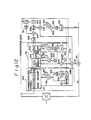
- FIG. 7 is a detailed block diagram of the echo canceller 60 shown in Fig. 6, wherein the same reference numbers represent the same parts in both figures.
- 71 is a convergence determination and specific pattern detection unit; 72 a convergence determination unit; 661, 662, 671 and 672 adders; 73 a a terminal connected to a transmitter (not shown); and 74 a terminal connected to a receiver (not shown).
- Transmission data S(k) is sent to the transmission line 69 through the hybrid circuit 68 and is supplied to the main tap unit 61.
- the transmission data S(k) is shifted by the main tap unit 61 and is further shifted by the subtap unit 62 through the one-bit delay circuit 63.
- An echo component X returning through the hybrid circuit 68 is supplied to the adder 661, and echo replicas ECR1 and ECR2 are read out from the main memory unit 64 and the submemory unit 65 in accordance with address signals from the main tap unit 61 and the subtap unit 62, respectively.
- the echo replicas ECRI and ECR2 are added by the adder 661, and an output from the adder 661 is supplied to the adder 662, whereby received data R(k) from which the echo component X is cancelled is output from the terminal 24.
- the echo component X can be cancelled by outputting the echo replica corresponding to the pattern of the transmission data S(k).
- the main tap unit 61, the subtap unit 62, the main memory unit 64, and the submemory unit 65 can be arranged by using random access memories.
- the functions of the convergence determination and specific pattern detection unit 71, the convergence determination unit 72, the adders 671 to 672, and the like can be realized by using the operation functions of a digital signal processor.
- the convergence determination and specific pattern detection unit 71 detects whether or not an address signal supplied from the main tap unit 61 to the main memory unit 64 represents a specific pattern, to supply a detection signal to the main memory unit 64 and the submemory unit 65. The unit 71 also determines that the received signal is converged when the echo replicas corresponding to the number of taps of the main tap unit 61 are written, based on the address signals, at all addresses of the main memory unit 64. The unit 71 then outputs a determination signal to the main memory unit 64 and the submemory unit 65.
- the convergence determination unit 72 determines that the received signal is converged when echo replicas corresponding to the number of taps of the subtap unit 62 are written at all addresses of the submemory unit 14 based on the address signals supplied from the subtap unit 62 to the submemory unit 65. After the determination, the unit 72 outputs a determination signal to the main memory unit 64 and the submemory unit 65.
- Convergence of the digital adaptive filter i.e., the echo canceller shown in Fig. 7, is performed using the random pattern as the transmission data S(k), and therefore, signal patterns output from the taps of the main tap unit 64 and the subtap unit 65 become random.
- the echo components obtained when the convergence determination and specific pattern detection unit 71 detects the specific pattern output from the main tap unit 61, are averaged a predetermined number of times, e.g., several times or several tens of times as later described in more detail.
- the echo component X generated by returning through the hybrid circuit 68 in accordance with the specific pattern is applied to the main memory unit 64 through the adders 662 and 671, and an averaging calculation is performed in an arithmetic logic unit (not shown).
- the averaged value is written as an echo replica in the area of the main memory unit 64 accessed by the specific pattern address signal.
- the echo replica written in the main memory unit 64 is subtracted from the echo component obtained when the convergence determination and specific pattern detection unit 71 detects the specific pattern, to obtain a replica, and this replica is written in the submemory unit 65 on the basis of the address signal from the subtap unit 62.
- the address signal input to the main memory unit 64 represents the specific pattern.
- the address signal input to the submemory unit 65 represents a random pattern, and therefore, this operation is repeated a plurality of times to thereby write echo replicas at all of the addresses of the submemory unit 65.
- the main memory unit 64 Upon convergence in the submemory unit 65, the main memory unit 64 writes a given echo replica in the area thereof accessed by the address signal.
- the given echo replica is obtained by subtracting the echo replicas written in the submemory unit 65 from the echo components obtained when the address signal from the main tap unit 61 represents a pattern other than the specific pattern.
- the convergence determination and specific pattern detection unit 71 determines that the echo replicas are written at all addresses of the main memory unit 64, the convergence is completed.
- the echo replicas with respect to a specific pattern applied to the main tap unit 61 are averaged to obtain an averaged echo replica, and the averaged echo replica is written to the main memory unit 64, whereby an echo replica for a pattern to the subtap unit 65 is obtained.
- the echo replica written in the submemory unit 65 has a greater precision than the echo replica written in the main memory unit 64, due to an increase in the bit length of the echo replica in the submemory unit 65 by at least one bit.
- an echo replica is obtained by subtracting the echo replica ECR2 from an echo component X.
- echo replicas are written to the main memory unit 64 and the submemory unit 65 in accordance with a predetermined algorithm, and at this time, the precision of the echo replica written to the submemory unit 65 is greater than the precision of the echo replica written to the main memory unit 64, due to an increase of the data bit length of the echo replica written to the submemory unit 65, whereby the increase of the maximum error due to the memory division can be suppressed so that both the reduction of the memory capacity by the memory division and the reduction of the residual error, compared with the case of a simple memory division without correcting the precision of the echo replica, can be obtained.
- the above-described embodiment includes the single main memory unit 64 and the single submemory unit 65, but the present invention is not restricted to this embodiment. Namely, the memory may be divided into a single main memory unit and a plurality of submemory units. In this case, the precision of each of the echo replicas written to the plurality of submemory units must be made greater than the precision of the echo replica written to the main memory unit.
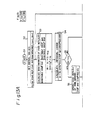
- Figure 8 is a flow chart for explaining a converging operation in the echo canceller shown in Fig. 7, according to the embodiment of the present invention.
- the transmission data S(k) represents a random pattern
- the convergence determination and specific pattern detection unit 71 determines whether or not an address signal applied from the main tap unit 61 to the main memory unit 64 represents a specific pattern.
- sync word When a random pattern during convergence is used as the transmission data S(k), a synchronization word (hereinafter referred to as sync word), for example, 9 symbols, is inserted in every 120 symbols to perform a frame synchronization in the same manner as in the normal transmission data. Therefore, the sync word may be used as the previously-mentioned specific pattern.
- the convergence determination and sync pattern detection unit 71 can accurately detect the sync word as a specific pattern. It is also possible to use a number of taps smaller than the number of bits of the sync word.
- a data pattern applied prior to the specific pattern is output from the taps of the subtap unit 62, and the specific pattern such as a sync word is inserted at a period different from that of the random pattern. Therefore, when the specific pattern is output from the main tap unit 64, the random pattern is output from the subtap unit 65.
- the echo component X returned from the hybrid circuit 68 and applied to the adder 662 is output as a residual echo component e without change.
- the residual echo component e obtained when the specific pattern is output from the main tap unit 61 is applied as an echo component to the main memory unit 64 through the adder 671.
- the echo components obtained upon every detection of the specific pattern are averaged a predetermined number of times in step 2. In this case, it is possible to use a sine algorithm, or this averaging calculation can be performed by using operation functions in the main memory unit 64 or other operation functions.
- the averaged echo component as a first echo replica for the specific pattern is written in the area of the main memory unit 64 accessed by the specific pattern address signal.
- the convergence determination and specific pattern detection unit 71 again detects a specific pattern in the main tap unit 64
- the first echo replica ECRI is read out from the main memory unit 64.
- a random pattern is output from the subtap unit 62, and by using this random pattern as an address signal, the residual echo component e2 is written in the submemory unit 65 as a second echo replica in step @.
- the convergence determination unit 72 determines in step @ whether or not a write operation of the first echo replicas at all addresses of the submemory unit 65 is completed. Similarly, the convergence determination and specific pattern detection unit 71 determines in step @ whether or not a write operation at all addresses of the main memory unit 64 is completed. When this determination is made, the convergence processing is completed.
- step 7 it is determined in step 7 whether or not a write operation of the second echo replicas at corresponding addresses of the submemory unit 65 is completed. This determination can be performed by the convergence determination unit 72. For example, when a write operation to all addresses of the submemory unit 65 is completed, the completion of the write operation is determined in step 7.
- the echo replica ECR2 from the submemory unit 65 is subtracted from the echo component X by the adder 671 to calculate the residual echo component el.
- the residual echo component el is written in the area of the main memory unit 64 accessed by the address signal from the main tap unit 61 in step@.
- the second echo replica for the pattern of the subtap unit 62 is obtained.
- the echo replica ECR2 from the submemory unit 65 is subtracted from the echo component X to obtain an echo replica, and even if the number of taps is large, accurate echo replicas can be set.
- the echo replicas corresponding to various patterns of the transmission data S(k) can be stored in the main memory unit 64 and the submemory unit 65 by the above convergence process.
- the echo replicas ECRI and ECR2 corresponding to a given pattern of the transmission data S(k) are respectively read out from the main memory unit 64 and the submemory unit 65 and are added by the adder 661, and a sum output from the adder 661 becomes an echo replica corresponding to the pattern of the transmission data S(k) at this time and is input to the adder 662. Therefore, received data R(k) from which the echo component X is cancelled can be output from the terminal 24.
- the submemory unit 65 When the submemory unit 65 is further divided into first and second submemory units, (1) an echo replica for the specific pattern is first written in the main memory unit 64, and (2) an echo replica generated by a residual echo component obtained when address signals for the main memory unit 64 and the first submemory unit represent specific patterns is written in the second submemory unit, and when the write operation at all addresses of the second submemory unit is completed, (3) the echo replica from the second submemory unit and the specific pattern echo replica from the main memory unit are added to each other, and an echo replica obtained by adding the added result and the echo component X is written in the first submemory unit.
- an echo replica obtained by subtracting the echo replicas from the first and second submemory units from the echo components is written in the main memory unit 64.
- the above can be applied to a case wherein the submemory unit is divided into a large number of submemory units.
- the echo replicas in the main memory unit 64 and the submemory unit 65 can be adaptively updated.
- FIG. 9 is a block diagram showing another embodiment-of the present invention.
- a subunit comprises a transversal filter instead of the submemory unit.
- 90 represents a tap coefficient setting unit
- 91 represents an adder.
- the other portions are the same as those in Fig. 7.
- the subunit of a transversal filter arrangement is constituted by the tap coefficient setting unit 90 and the adder 91.
- Transmission data S(k) is output to the transmission line 69 through the hybrid circuit 68 and is supplied to and shifted by the main tap unit 61.
- the transmission data S(k) is supplied to and further shifted by the subtap unit 62, which includes one-bit delay circuits T, respectively.
- the convergence determination unit 72 determines a convergence of the setting of the tap coefficients in the tap coefficient setting unit 90 formed by a transversal filter when a residual echo component e2 applied to the tap coefficient setting unit 90 falls within a predetermined range.
- a write operation of echo replicas in the main memory unit 64 during convergence is substantially the same as in the previous embodiment shown in Fig. 7.
- the tap coefficient is set by the tap coefficient setting unit 90 based on a residual echo component obtained upon detection of the specific pattern from the main tap unit 61.
- FIG. 10 is a flow chart explaining the convergence process in the embodiment shown in Fig. 9.
- transmission data S(k) having a random pattern is supplied to the terminal 73.
- the convergence determination and specific pattern detection unit 71 detects in step 11 whether or not a specific pattern such as a sync word is output from the main tap unit 61.
- the echo component obtained when the specific pattern such as a sync word is output from the main tap unit 61 is held, and the echo components are averaged a predetermined number of times as in step 2 (step @) .
- the average echo component is written as a specific pattern echo replica for the transmission data in the area of the main memory unit 64 accessed by the specific pattern address signal.
- Tap coefficients of the tap coefficient setting unit 90 are set in accordance with a known algorithm using the residual echo component e2 (step 14 ) .
- step @ It is then determined in step @ whether the specific pattern is output from the main tap unit 61 a predetermined number of times. That is, it is determined whether or not the tap coefficients of the tap coefficient setting unit 90 are repeated the predetermined number of times. If the tap coefficients are repeatedly set a predetermined number of times, it is then determined in step @ whether or not the write operation at all addresses of the main memory unit 64 is completed in the same manner as in step 6. If the write operation at addresses is completed, the convergence processing is completed.
- step @ When an address signal except for the specific pattern address signal is supplied from the main tap unit 61 to the main memory unit 64, it is determined in step @ whether or not the specific pattern appears a predetermined number of times, as in step @ .
- the subunit of the transversal filter arrangement repeatedly sets the tap coefficients a predetermined number of times, and the convergence processing of the subunit is determined.
- the residual echo component el is written in the main memory unit 64 as an echo replica for the corresponding pattern from the main tap unit 61 in step 19 .
- echo components corresponding to the taps of the subtap unit 62 are linear in correspondence with the foot portions of an impulse response.
- the echo components corresponding to the taps of the main tap units 61 vary depending on the patterns of the transmission data S(k). In this case, the echo replicas corresponding to the patterns can be accurately stored in the main memory unit 64.
- the echo replica ECR1 read out from the main memory unit 64 and the echo replica ECR2 output from the adder 91 are added by the adder 661 at the time of data transmission.
- An echo replica (ECR1 + ECR2) corresponding to the corresponding pattern of the transmission data is supplied to the adder 662, to thereby cancel the echo component X.
- the echo replicas of the main memory unit 64 and the tap coefficients of the tap coefficient setting unit 90 can be adaptively updated.
- the tap unit for shifting the transmission data and outputting the parallel data is divided into the main tap unit 61 and an arbitrary number of subtap units.
- the parallel signal output from the main tap unit 61 is supplied to the main memory unit 64 as the address signal, and the parallel signals output from the subtap units are supplied to the respective subunits.
- the digital adaptive filter corresponds to a memory division type filter, thereby greatly reducing the memory capacity.
- the echo components obtained when the specific patterns such as sync words are output from the main tap unit 61 are averaged a predetermined number of times, and the averaged value is written in the main memory unit 64 accessed by the specific pattern address data, to thereby obtain a very precise echo replica for the specific pattern.
- the residual echo component obtained by subtracting the echo replica of the main memory unit 64 from the echo component obtained upon detection of the specific pattern is written or tap coefficients are set for the subunits.
- the subunits can be accurately set and controlled on the basis of the very precise echo replicas.
- the echo replicas obtained from the subunits can be made very precise, and the division loss does not occur.
- the echo replicas are written in the main memory unit 64 based on the residual echoes obtained by subtracting the echo replicas of the already converged subunits from the echo components, and therefore, very precise echo replicas can be written in the main memory unit 64.
- the time required for fetch processing can be shortened.
- Figure 11 is a block diagram showing a principle constitution of an adaptive digital filter according to still another embodiment of the present invention.
- the adaptive digital filter includes a look-up table type main filter unit 911 for generating main components of a pseudo signal, a subfilter unit 72 for generating secondary components of the pseudo signal, and a synthesizing portion 115 for synthesizing the pseudo signal from the main components and secondary components.
- the main filter unit 111 and a part of the subfilter unit 112 are substantially the same as the main memory unit 64 and the submemory unit 65, respectively, in the first embodiment shown in Fig. 6.
- the content of the main filter unit 111 is updated by an update unit 113 according to a calculation directly based on an error between an input signal and the pseudo signal, and if the error is small, the main filter unit 111 is updated depending on the polarity of the error and according to a predetermined step size that is smaller than "I".
- the secondary filter unit 112 is updated depending on the polarity of the error according to a predetermined step size that is smaller than "1".
- FIG. 12 is a block diagram showing respective functions realized by the DSP.
- 100 is a main table portion, 120 a subtable portion, 130 is an IIR filter portion, 41 and 42 adders, and 43 a 2-wire/4-wire converting portion (hybrid circuit).
- the main table portion 100 and the submemory table portion 120 form a table division type table look-up echo .canceller.
- the main table portion 100 includes a main memory unit 101, a tap unit 102 having six taps, a residual error monitoring portion 103, a sign detecting portion 104, a step size deciding portion 105, an adding portion 106, and a delay portion 107.
- the secondary table portion 120 is composed of two submemory units each having two taps.
- the secondary table portion 120 includes submemory units 201 and 202, tap portions 203 and 204, a sign detecting portion 205, step size deciding portions 206 and 207, adding portions 208, 209 and 212, and delay portions 210 and 211.
- the IIR filter portion 130 includes a sign detecting portion 301, a step size deciding portion 302, adding portions 303 and 307, delay portions 304 and 309, a multiply portion 305, registers 306, 308 and 310, and an attenuation coefficient portion 311, etc.
- the precision of the echo replica written in the submemory unit 201 or 202 is greater than the precision of the echo replica in the main memory 101.
- the primary IIR filter portion 130 is disposed after the memory division type echo canceller.
- Fig. 13 is a flowchart showing a convergent algorithm of the echo canceller of the embodiment.
- Step S2 initial values are set (Step S2). Namely, the contents of the main memory unit 101, submemory units 201 and 202, registers 398 and 310, etc., are cleared and set to "0",
- ERM(fo) is an echo replica read out of the main memory unit 101 at an address fo
- ERSI(go) an echo replica read out of the submemory unit 201 at an address go
- ERS2-(ho) an echo replica read out of the submemory unit 202 at an address h o
- ER3 an echo replica output from the primary IIR filter portion 130.
- the echo replica ER3 is calculated as follows:
- D r is an attenuation coefficient of the primary IIR filter portion 130
- C s is a weight coefficient of the primary IIR filter portion 130
- ao to a 10 are transmission symbols.
- Step S4 a residual error e is operated as follows (Step S4):
- X k is an input, i.e., a returning echo.
- Step S5 It is then determined whether or not the operated residual error e k satisfies
- y is a positive numeral smaller than I.
- Step S6 If the expression
- the already stored echo replica ERM k -(fo) is read out of the main memory unit 101 at the address f o and added to the residual error Ek , and a result of the addition is set as the echo replica updated value ERM k+1 (f 0 ) and again stored in the main memory unit 101.
- These processes are carried out in the adding portion 106 and delay portion 107, etc.
- Echo replicas of the submemory units 201 and 202 are updated as follows, depending on the polarity of the residual error ⁇ k (Step S7).
- SI and S2 are step sizes that are positive numerals and smaller than I (0 ⁇ SM, S1, S2, S3 ... «1).
- the polarity of the residual error Ek is detected by the sign detecting portion 205, and if the sign is negative, the echo replica ERS1 k (g o ) is read out of the submemory unit 201 at the address go and added to the very small step size SI to obtain the echo replica updated value ERS1 k+l (go), which is again stored in the submemory unit 201.
- the step size SI is subtracted. Accordingly, the echo replica in the submemory unit 201 is gradually converged.
- the echo replica ERS2 of the submemory unit 202 is updated stepwise. These processes are carried out in the sign detecting portion 205, step size deciding portions 206 and 207, adding portions 208 and 209, and delay portions 210 and 211, etc.
- Step S7 is carried out to update the echo replicas stepwise.
- the attenuation coefficient D r of the primary IIR filter portion 130 is fixed, and only the polarity of the residual error Ek is monitored.
- the weight coefficient C s is sequentially updated stepwise according to a sign algorithm based on the minute step size S3 (0 ⁇ S3 «i
- Step SIO The above-mentioned processes are repeated until the echo input signal in the canceller has properly converged.
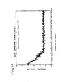
- Figure 14 shows a result of computer simulation of echo suppressing characteristics of the echo canceller based on the above-mentioned convergent algorithm employing the 2BIQ codes.
- the ordinate indicates residual echoes and the abscissa represents iteration (number of repetitions). Since the embodiment quantizes the input value X k with five decimal bits, a logical maximum echo suppression quantity is -30 dB. As a result of the simulation, the echo suppression quantity is about -26 dB, i.e., an ideal echo suppression has been achieved.
- the embodiment is composed of the filter portion of a main memory unit, which is followed by the submemory units and IIR filter, this arrangement is not intended to limit the invention.
- the invention may be realized with a main memory unit and submemory units; with a main memory unit, submemory units and a transversal filter; with a main memory unit and a transversal filter; with a main memory unit, a transversal filter and an IIR filter; or with a main memory unit and an IIR filter.
- the embodiment has employed the sign algorithm for executing the stepwise updating, a stochastic iteration algorithm, or an adaptive step sign algorithm, etc., may be employed.
- the embodiment has changed the updating methods of the main memory unit from one to another by comparing the residual error « with the predetermined value "y," it may automatically be changed from one to another based on a timer after a time within which the residual error e becomes sufficiently small.
- the adaptive digital filter of the invention is generally applicable for apparatuses such as waveform generators and equalizers generating optional waveforms.
- an adaptive digital filter is obtained which can accurately converge the input signal at a high speed, and in which a residual error due to memory division is reduced.
Landscapes
- Cable Transmission Systems, Equalization Of Radio And Reduction Of Echo (AREA)
- Filters That Use Time-Delay Elements (AREA)
Applications Claiming Priority (4)
| Application Number | Priority Date | Filing Date | Title |
|---|---|---|---|
| JP18056588A JPH0230225A (ja) | 1988-07-20 | 1988-07-20 | ディジタルアダプティブフィルタ |
| JP180565/88 | 1988-07-20 | ||
| JP111664/89 | 1989-04-28 | ||
| JP11166489A JPH02288718A (ja) | 1989-04-28 | 1989-04-28 | 適応型ディジタルフィルタの収束方法 |
Publications (2)
| Publication Number | Publication Date |
|---|---|
| EP0351843A2 true EP0351843A2 (de) | 1990-01-24 |
| EP0351843A3 EP0351843A3 (de) | 1990-12-19 |
Family
ID=26451006
Family Applications (1)
| Application Number | Title | Priority Date | Filing Date |
|---|---|---|---|
| EP19890113338 Withdrawn EP0351843A3 (de) | 1988-07-20 | 1989-07-20 | Digitales adaptives Filter und Konvergenzverfahren darin |
Country Status (3)
| Country | Link |
|---|---|
| US (1) | US5007044A (de) |
| EP (1) | EP0351843A3 (de) |
| CA (1) | CA1315356C (de) |
Cited By (2)
| Publication number | Priority date | Publication date | Assignee | Title |
|---|---|---|---|---|
| EP0492647B1 (de) * | 1990-12-27 | 1997-04-23 | Nec Corporation | Adaptiver Filter geeignet zur schnellen Identifikation eines unbekannten Systems |
| WO2001056184A1 (en) * | 2000-01-25 | 2001-08-02 | Aware, Inc. | System and method for the application of an lms method to updating an echo canceller in an adsl modem |
Families Citing this family (14)
| Publication number | Priority date | Publication date | Assignee | Title |
|---|---|---|---|---|
| JPH0344218A (ja) * | 1989-07-12 | 1991-02-26 | Fujitsu Ltd | 適応形エコーキャンセラ |
| US5146494A (en) * | 1989-07-31 | 1992-09-08 | At&T Bell Laboratories | Overlapping look-up-and-add echo canceller requiring a smaller memory size |
| US5418778A (en) * | 1992-02-14 | 1995-05-23 | Itt Corporation | Local and remote echo canceling apparatus particularly adapted for use in a full duplex modem |
| US5295136A (en) * | 1992-04-13 | 1994-03-15 | Motorola, Inc. | Method of performing convergence in a, least mean square, adaptive filter, echo canceller |
| US5329586A (en) * | 1992-05-29 | 1994-07-12 | At&T Bell Laboratories | Nonlinear echo canceller for data signals using a non-redundant distributed lookup-table architecture |
| US5390364A (en) * | 1992-11-02 | 1995-02-14 | Harris Corporation | Least-mean squares adaptive digital filter havings variable size loop bandwidth |
| US5896449A (en) * | 1993-12-02 | 1999-04-20 | Alcatel Usa Sourcing L.P. | Voice enhancement system and method |
| US5471527A (en) * | 1993-12-02 | 1995-11-28 | Dsc Communications Corporation | Voice enhancement system and method |
| DE4430189A1 (de) * | 1994-08-25 | 1996-02-29 | Sel Alcatel Ag | Verfahren zur adaptiven Echokompensation |
| JPH08265224A (ja) * | 1995-03-22 | 1996-10-11 | Nec Corp | エコーキャンセラ |
| US5978473A (en) * | 1995-12-27 | 1999-11-02 | Ericsson Inc. | Gauging convergence of adaptive filters |
| JP2000209135A (ja) * | 1999-01-20 | 2000-07-28 | Oki Electric Ind Co Ltd | エコ―キャンセラ |
| JP2000252881A (ja) * | 1999-02-25 | 2000-09-14 | Mitsubishi Electric Corp | ダブルトーク検知装置並びにエコーキャンセラ装置およびエコーサプレッサー装置 |
| ATE368344T1 (de) * | 1999-04-22 | 2007-08-15 | Broadcom Corp | Gigabit-ethernt mit zeitverschiebungen zwischen verdrillten leitungspaaren |
Family Cites Families (12)
| Publication number | Priority date | Publication date | Assignee | Title |
|---|---|---|---|---|
| SE426765B (sv) * | 1981-11-02 | 1983-02-07 | Ellemtel Utvecklings Ab | Balansfilter av fir-typ ingaende i sendar-mottagarenheten i ett telekommunikationssystem |
| FR2528643A1 (fr) * | 1982-06-14 | 1983-12-16 | Trt Telecom Radio Electr | Procede destine a reduire le temps de convergence d'un annuleur d'echo et dispositif utilise pour mettre en oeuvre ce procede |
| JPS59211338A (ja) * | 1983-05-17 | 1984-11-30 | Nec Corp | エコ−キヤンセラ−装置 |
| US4605826A (en) * | 1982-06-23 | 1986-08-12 | Nec Corporation | Echo canceler with cascaded filter structure |
| CA1238381A (en) * | 1985-03-14 | 1988-06-21 | Ephraim Arnon | Multi-stage echo canceller |
| DE3515832A1 (de) * | 1985-05-02 | 1986-11-06 | Siemens AG, 1000 Berlin und 8000 München | Hybrider echokompensator |
| US4811342A (en) * | 1985-11-12 | 1989-03-07 | Racal Data Communications Inc. | High speed analog echo canceller |
| NL8600817A (nl) * | 1986-03-28 | 1987-10-16 | At & T & Philips Telecomm | Adaptief filter voor het vormen van een echokompensatiesignaal in een zend-ontvangstelsel voor het in duplexvorm bedrijven van digitale communicatie over een enkel geleiderpaar. |
| US4868874A (en) * | 1986-04-18 | 1989-09-19 | Hitachi, Ltd. | Echo canceller |
| JPS62291223A (ja) * | 1986-06-10 | 1987-12-18 | Nec Corp | アダプテイブ・フイルタ適応化方法及び装置 |
| US4823382A (en) * | 1986-10-01 | 1989-04-18 | Racal Data Communications Inc. | Echo canceller with dynamically positioned adaptive filter taps |
| JPH0779290B2 (ja) * | 1987-01-13 | 1995-08-23 | 日本電気株式会社 | エコ−除去装置 |
-
1989
- 1989-07-19 CA CA000606172A patent/CA1315356C/en not_active Expired - Fee Related
- 1989-07-20 EP EP19890113338 patent/EP0351843A3/de not_active Withdrawn
- 1989-07-20 US US07/382,413 patent/US5007044A/en not_active Expired - Fee Related
Cited By (6)
| Publication number | Priority date | Publication date | Assignee | Title |
|---|---|---|---|---|
| EP0492647B1 (de) * | 1990-12-27 | 1997-04-23 | Nec Corporation | Adaptiver Filter geeignet zur schnellen Identifikation eines unbekannten Systems |
| WO2001056184A1 (en) * | 2000-01-25 | 2001-08-02 | Aware, Inc. | System and method for the application of an lms method to updating an echo canceller in an adsl modem |
| EP1995884A1 (de) * | 2000-01-25 | 2008-11-26 | Aware, Inc. | System und Verfahren zur Anwendung von einem lMS Verfahren zur Aktualisierung eines Echounterdrückers in einem ADSL Modem |
| US8391191B2 (en) | 2000-01-25 | 2013-03-05 | Tq Delta, Llc | System and method for the application on an LMS method to updating an echo canceller in an ADSL modem |
| US8649305B2 (en) | 2000-01-25 | 2014-02-11 | Tq Delta, Llc | System and method for the application of an LMS method to updating an echo canceller in an ADSL modem |
| US9065886B2 (en) | 2000-01-25 | 2015-06-23 | Tq Delta, Llc | System and method for the application of an LMS method to updating an echo canceller in a multicarrier transceiver |
Also Published As
| Publication number | Publication date |
|---|---|
| EP0351843A3 (de) | 1990-12-19 |
| US5007044A (en) | 1991-04-09 |
| CA1315356C (en) | 1993-03-30 |
Similar Documents
| Publication | Publication Date | Title |
|---|---|---|
| EP0351843A2 (de) | Digitales adaptives Filter und Konvergenzverfahren darin | |
| CA2058495C (en) | Adaptive filter capable of quickly identifying an unknown system | |
| AU606392B2 (en) | Circuit for cancelling whole or part of a waveform using nonrecursive and recursive filters | |
| US4736414A (en) | Method of and device for the digital cancellation of the echo generated in connections with time-varying characteristics | |
| CA2020804C (en) | Adaptive echo canceller | |
| US5796820A (en) | Recovery of previous filter coefficients with smaller capacity memory | |
| KR100404012B1 (ko) | 적응성 비선형 에코 보상기 | |
| JP2924762B2 (ja) | アダプティブフィルタ及びその適応化方法 | |
| US5748726A (en) | Echo canceller | |
| KR20000070020A (ko) | 혼합된 고정 소수점 또는 부동 소수점 및 블럭 스케일 부동 소수점 연산자를 가진 적응 필터 시스템 | |
| JP2581458B2 (ja) | アダプティブフィルタの適応化方法及び装置 | |
| EP0383360B1 (de) | Adaptive Erkennungseinrichtung | |
| JP2540974B2 (ja) | アダプティブ・フィルタ適応化方法及び装置 | |
| JPH07202766A (ja) | 適応フィルタによる未知システム同定の方法及び装置 | |
| CN100562828C (zh) | 保证电压余量最大的电平输出装置及其方法 | |
| JPH02288718A (ja) | 適応型ディジタルフィルタの収束方法 | |
| KR100259207B1 (ko) | 적응디지탈 필터링방법 및 그 장치 | |
| JPH01212127A (ja) | エコー除去方法及びエコー除去装置 | |
| JPH04157848A (ja) | シンボルコーダ | |
| JPH0865213A (ja) | エコーキャンセラ | |
| JPH01212129A (ja) | エコー除去方法及びエコー除去装置 | |
| JPH03284010A (ja) | 適応型通信路インパルスレスポンス推定方式 | |
| JPH0541680A (ja) | 回線スリツプ対応型エコーキヤンセラ | |
| JPH0779179A (ja) | エコーキャンセラ及び通信装置 | |
| JPS647704B2 (de) |
Legal Events
| Date | Code | Title | Description |
|---|---|---|---|
| PUAI | Public reference made under article 153(3) epc to a published international application that has entered the european phase |
Free format text: ORIGINAL CODE: 0009012 |
|
| AK | Designated contracting states |
Kind code of ref document: A2 Designated state(s): DE FR GB IT SE |
|
| PUAL | Search report despatched |
Free format text: ORIGINAL CODE: 0009013 |
|
| AK | Designated contracting states |
Kind code of ref document: A3 Designated state(s): DE FR GB IT SE |
|
| 17P | Request for examination filed |
Effective date: 19901220 |
|
| 17Q | First examination report despatched |
Effective date: 19940526 |
|
| STAA | Information on the status of an ep patent application or granted ep patent |
Free format text: STATUS: THE APPLICATION IS DEEMED TO BE WITHDRAWN |
|
| 18D | Application deemed to be withdrawn |
Effective date: 19941206 |