EP0568978A1 - Kreiselkompass - Google Patents
Kreiselkompass Download PDFInfo
- Publication number
- EP0568978A1 EP0568978A1 EP93107219A EP93107219A EP0568978A1 EP 0568978 A1 EP0568978 A1 EP 0568978A1 EP 93107219 A EP93107219 A EP 93107219A EP 93107219 A EP93107219 A EP 93107219A EP 0568978 A1 EP0568978 A1 EP 0568978A1
- Authority
- EP
- European Patent Office
- Prior art keywords
- angular velocity
- circuit
- output signal
- velocity sensor
- gyro
- Prior art date
- Legal status (The legal status is an assumption and is not a legal conclusion. Google has not performed a legal analysis and makes no representation as to the accuracy of the status listed.)
- Granted
Links
Images




Classifications
-
- G—PHYSICS
- G01—MEASURING; TESTING
- G01C—MEASURING DISTANCES, LEVELS OR BEARINGS; SURVEYING; NAVIGATION; GYROSCOPIC INSTRUMENTS; PHOTOGRAMMETRY OR VIDEOGRAMMETRY
- G01C19/00—Gyroscopes; Turn-sensitive devices using vibrating masses; Turn-sensitive devices without moving masses; Measuring angular rate using gyroscopic effects
- G01C19/56—Turn-sensitive devices using vibrating masses, e.g. vibratory angular rate sensors based on Coriolis forces
- G01C19/5642—Turn-sensitive devices using vibrating masses, e.g. vibratory angular rate sensors based on Coriolis forces using vibrating bars or beams
- G01C19/5649—Signal processing
Definitions
- the present invention relates to a gyro-compass, particularly, it relates to a gyro-compass for detecting a position of a moving body such as an automobile and the like.
- an angular velocity sensor or the like in order to measure a position of, for example, an automobile, an angular velocity sensor or the like has been used.
- the position of the automobile was detected from a moving direction of the automobile detected by the angular velocity sensor and the like, and a moving distance obtained from a speed meter of the automobile.
- a primary object of the present invention to provide a gyro-compass capable of measuring both a rotational angular velocity and a linear velocity or acceleration accurately, for measuring a moving direction and moving distance of a moving body such as an automobile and the like accurately.
- the present invention is directed to a gyro-compass comprising an angular velocity sensor, angular velocity applying means for applying a known rotational angular velocity to the angular velocity sensor, a plurality of synchronous detection circuits for detecting an output signal of the angular velocity sensor in synchronism with different phases, a plurality of smoothing circuits for smoothing output signals of the plurality of synchronous detection circuits, a composite circuit for composing output signals of the plurality of smoothing circuits, a differential circuit for obtaining a difference between one output signal of the plurality of smoothing circuits and an output signal of the composite circuit, and a separate differential circuit for obtaining a difference between an output of the differential circuit and a signal corresponding to the known rotational angular velocity applied by the angular velocity applying means.
- the known rotational angular velocity is applied to the angular velocity sensor
- a signal corresponding to the linear velocity or acceleration is superposed on the output signal of the angular velocity sensor.
- the rotational angular velocity is applied to the angular velocity sensor from the outside, its output signal becomes a composite signal of the signal corresponding to the known rotational angular velocity, the signal corresponding to the external rotational angular velocity and the signal corresponding to the linear velocity or acceleration.
- the signal corresponding to the linear velocity or acceleration is superposed on the output signal of the angular velocity sensor. Since only the signal corresponding to the linear velocity or acceleration can be taken out, the linear velocity or acceleration can be detected. Furthermore, by integrating the obtained velocity or acceleration, a moving distance can be known. Since the signal corresponding to the rotational angular velocity applied to the angular velocity sensor from the outside can be obtained, the rotational angular velocity can be known. As such, since both the external rotational angular velocity and the linear velocity or acceleration can be detected, when this gyro-compass is installed on an automobile and the like, the position of the automobile can be detected accurately.
- Fig. 1 is a block diagram showing one embodiment of the present invention.
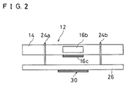
- Fig. 2 is a side view showing a surroundings of an angular velocity sensor of a gyro-compass shown in Fig. 1.
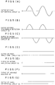
- Figs. 3(A)-3(G) are graphs showing output signals of respective circuits, when only a known rotational angular velocity is applied to an angular velocity sensor.
- Figs. 4(A)-4(G) are graphs showing output signals of respective circuits, when a known rotational angular velocity and a linear velocity or acceleration are applied to an angular velocity sensor.
- Figs. 5(A)-5(G) are graphs showing output signals of respective circuits, when a known rotational angular velocity and an external rotational angular velocity are applied to an angular velocity sensor.
- Figs. 6(A)-6(G) are graphs showing output signals of respective circuits, when a known rotational angular velocity, a linear velocity or acceleration and an external rotational angular velocity are applied to an angular velocity sensor.
- FIG. 1 is a block diagram showing one embodiment of the present invention.
- a gyro-compass 10 includes an angular velocity sensor 12.
- the angular velocity sensor 12 includes a vibrator 14.
- the vibrator 14 is formed into a regular triangular columnar shape by, in general, a material generating mechanical vibration such as elinvar, iron-nickel alloy, quartz, glass, crystal, ceramics and the like.
- piezoelectric elements 16a, 16b and 16c are formed respectively.
- the piezoelectric element 16a includes a piezoelectric layer 18a, on both surfaces of which electrodes 20a and 22a are formed.
- One electrode 22a is bonded to the side face of the vibrator 14.
- the piezoelectric elements 16b, 16c include piezoelectric layer 18b, 18c, on both surfaces of which electrodes 20b, 22b and electrodes 20c, 22c are formed.
- One electrodes 22b, 22c of the piezoelectric elements 16b, 16c are bonded to the side faces of the vibrator 14.
- the vicinity of nodal points of the vibrator 14 are supported by support members 24a and 24b consisting of, for example, a metal wire.
- the support members 24a and 24b are secured to the vicinity of the nodal points by, for example, welding.
- the support members 24a, 24b are secured to a support base 26.
- One end of the support base 26 is supported rotatably by a shaft 28.
- the shaft 28 is mounted so as to be parallel to an axial direction of the vibrator 14.
- a piezoelectric element 30 as angular velocity applying means is formed on the lower face of the support base 26, a piezoelectric element 30 as angular velocity applying means is formed.
- the piezoelectric element 30 is consisting of a piezoelectric layer 30a and electrodes 30b, 30c formed on both surfaces of the piezoelectric layer 30a.
- the piezoelectric elements 16a-16c of the angular velocity sensor 12 any two thereof are used for detection and these two or other one are used for driving.
- the piezoelectric elements 16a and 16b are used for detection and driving, and the piezoelectric element 16c is used for feedback.
- an oscillation circuit 40 and a phase circuit 42 are connected as a feedback loop for self-oscillation driving of the angular velocity sensor 12.
- a driving signal is given by the oscillation circuit 40 and the phase circuit 42, and the angular velocity sensor 12 is bent and vibrated in a direction orthogonal to a face whereon the piezoelectric element 16c is formed.
- the detecting piezoelectric elements 16a, 16b are connected to a first differential circuit 44.
- the first differential circuit 44 a difference between the outputs of the piezoelectric elements 16a and 16b is detected.
- the output of the first differential circuit 44 is inputted to a first synchronous detection circuit 46 and a second synchronous detection circuit 48.
- a synchronous signal is given from the phase circuit 42.
- the first synchronous detection circuit 46 and the second synchronous detection circuit 48 in synchronism with the phases which differ from each other by 180°, the output signal of the first differential circuit 44 is detected.
- the first synchronous detection circuit 46 is connected to a first smoothing circuit 50, in turn the first smoothing circuit 50 is connected to a first amplifying circuit 52.
- first smoothing circuit 50 an output signal of the first synchronous detection circuit 46 is smoothed, and the smoothed signal is amplified in the first amplifying circuit 52.
- second synchronous detection circuit 48 is connected to a second smoothing circuit 54, in turn, the second smoothing circuit 54 is connected to a second amplifying circuit 56.
- an output signal of the second synchronous detection circuit 48 is smoothed, and the smoothed signal is amplified in the second amplifying circuit 56.
- Output signals of the first amplifying circuit 52 and the second amplifying circuit 56 are connected to a variable resistor 58 as composite circuit.
- the variable resistor 58 is so adjusted that its output becomes zero when the linear velocity or acceleration is not applied to the gyro-compass 10.
- output signals of the variable resistor 58 and the first amplifying circuit 52 are inputted to a second differential circuit 60.
- the output signal of the variable resistor 58 is subtracted from the output signal of the first amplifying circuit 52.
- an oscillation circuit 62 for driving the piezoelectric element 30 is connected to the piezoelectric element 30 as the angular velocity applying means.
- a signal of the oscillation circuit 62 the support base 26 is vibrated as drawing an arc about the shaft 28.
- a signal corresponding to the rotational angular velocity applied to the angular velocity sensor 12 by driving the support base 26 is outputted.
- the signal corresponding to the known rotational angular velocity is obtained by amplifying, and further, smoothing the signal for driving the piezoelectric element 30.
- the signal corresponding to the known rotational angular velocity and the output signal of the second differential circuit 60 are inputted to a third differential circuit 64.
- the signal corresponding to the known rotational angular velocity is subtracted from the output signal of the second differential circuit 60.
- the signal corresponding to the known rotational angular velocity is the same signal as the output signal obtained from the second differential circuit 60, when the rotational angular velocity and the linear velocity or acceleration are not applied from the outside.
- the operation of the gyro-compass 10 is described.
- a case where the piezoelectric element 30 is not driven and the known rotational angular velocity is not applied to the angular velocity sensor 12 is considered.
- the vibrator 14 of the angular velocity sensor 12 is bent and vibrated in a direction orthogonal to a face whereon the piezoelectric element 16c is formed.
- the output of the first differential circuit 44 becomes zero. Therefore, the outputs of the variable resistor 58 and the third differential circuit 64 are both zero, and it is clear that neither the rotational angular velocity nor the linear velocity or acceleration are applied.
- the support base 26 is moved and the known rotational angular velocity is applied to the angular velocity sensor 12 is considered.
- the output signal is generated in the first differential circuit 44.
- the rotational angular velocity applied to the angular velocity sensor 12 is applied at a fixed period and amplitude by the oscillation circuit 62. Therefore, the output of the first differential circuit 44 is outputted as, for example, a sine wave as shown in Fig. 3 (A).
- the output signal of the first synchronous detection circuit 46 and the output signals of the second synchronous detection circuit 48 are in the opposite direction with each other, and have the same strength. Therefore, when these signals are smoothed and amplified, as shown in Fig. 3 (D) and Fig. 3 (E), D.C. outputs which are in the opposite direction with each other and having the same strength are obtained.
- these signals are composed in the variable resistor 58, as shown in Fig. 3 (F), its output becomes zero. Thereby, it is clear that the linear acceleration is not applied.
- the output of the first amplifying circuit 52 is the output signal of the first differential circuit 44 whose positive side is detected and amplified. Since the output of the variable resistor 58 is zero, the output signal of the second differential circuit 60 becomes the same output signal as the first amplifying circuit 52.
- the output signal of the second differential circuit 60 is a signal corresponding to the known rotational angular velocity applied to the angular velocity sensor 12. Thus, as shown in Fig. 3 (G), an output from the third differential circuit 64 becomes zero. Thereby, it is clear that the rotational angular velocity is not applied to the angular velocity sensor 12 from the outside.
- an amplitude of the output signal of the first differential circuit 44 is same as that shown in Fig. 3 (A).
- This output signal is detected in synchronism with phases which differ from each other by 180° , in the first synchronous detection circuit 46 and the second synchronous detection circuit 48. That is, in the first synchronous detection circuit 46, as shown in Fig. 4 (B), the positive side of the output signal of the first differential circuit 44 is detected. In the second synchronous detection circuit 48, as shown in Fig. 4 (C), the negative side of the output signal of the first differential circuit 44 is detected.
- the output signal of the variable resistor 58 is subtracted from the output signal of the first amplifying circuit 52. Therefore, from the second differential circuit 60, a signal obtained by subtracting the signal by the linear velocity or acceleration applied to the angular velocity sensor 12, from the output signal of the first amplifying circuit 52 is outputted. This signal is a signal corresponding to the known rotational angular velocity applied to the angular velocity sensor 12.
- the output from the third differential circuit becomes zero. Thereby, it is clear that the rotational angular velocity is not applied to the angular velocity sensor 12 from the outside.
- the output signal of the first synchronous detection circuit 46 becomes a positive side signal centering around 0V, as shown in Fig. 5 (B).
- the output signal of the second synchronous detection circuit 48 becomes a negative side signal centering around 0V, as shown in Fig. 5 (C).
- the output signal of the variable resistor 58 is subtracted from the output signal of the first amplifying circuit 52, since the output of the variable resistor 58 is zero, the output signal of the first amplifying circuit 52 is outputted from the second differential circuit 60 as it is.
- signals corresponding to the known rotational angular velocity applied to the angular velocity sensor 12 and the rotational angular velocity applied from the outside are included.
- the signal corresponding to the known rotational angular velocity is subtracted in the third differential circuit 64, as shown in Fig. 5 (G)
- only the signal corresponding to the rotational angular velocity applied from the outside is outputted. From this signal, the rotational angular velocity applied to the angular velocity sensor 12 from the outside can be known.
- a negative side voltage is outputted.
- These signals are smoothed in the first smoothing circuit 50 and the second smoothing circuit 54, and further, amplified in the first amplifying circuit 52 and second amplifying circuit 56.
- a high voltage is outputted
- a low voltage is outputted.
- the variable resistor 58 By composing these signals in the variable resistor 58, the signals corresponding to the known rotational angular velocity and the rotational angular velocity applied from the outside are canceled. From the variable resistor 58, only the output signal corresponding to the linear velocity or acceleration is outputted.
- the output signal of the variable resistor 58 is subtracted from the output signal of the first amplifying circuit 52. Therefore, the output of the second differential circuit 60 becomes the signal corresponding to the known rotational angular velocity applied to the angular velocity sensor 12 and the rotational angular velocity applied from the outside.
- the signal corresponding to the known rotational angular velocity is subtracted in the third differential circuit 64, only the signal corresponding to the rotational angular velocity applied from the outside is outputted. From this signal, the rotational angular velocity applied from the outside can be known.
- the amplitude of the output signal of the first differential circuit 44 becomes larger by the external rotational angular velocity, and the output signal of the first differential circuit 44 moves to the positive side by the linear velocity or acceleration.
- the output signal of the first differential circuit 44 becomes smaller or moves to the negative side.
- both the rotational angular velocity and the linear velocity or acceleration can be measured.
- a moving distance can be known.
- a moving direction can be known from the rotational angular velocity, even when the automobile and the like is moved, its position can be detected accurately.
- the moving distance and direction can be measured accurately, errors due to the amount of air in the tires and unevenness of a road can be eliminated.
- connections at a time of installing on the automobile can be simplified.
- an axis of the vibrator 14 is in a horizontal direction or in a vertical direction. It may also be arranged such that, the axis of the vibrator 14 is in a direction other than the horizontal and vertical directions. That is, in the gyro-compass 10, the rotational angular velocity about the axis of the vibrator 14, and the linear velocity or acceleration orthogonal to the axis can be measured. Thus, by using a plurality of gyro-compasses 10 and changing the directions of arrangement, the rotational angular velocity and the linear velocity or acceleration in all directions can be measured.
- the angular velocity sensor 12 is bent and vibrated by self-oscillation driving, it is also possible to be bent and vibrated by separate-oscillation driving.
- the angular velocity sensor it is not limited to a vibration type, it is also possible to use other angular velocity sensors such as an optical fiber type, a gas rate type and a rotational-gyroscope.
- an optical fiber type By applying the known rotational angular velocity to these angular velocity sensors, both the rotational angular velocity from the outside and the linear velocity or acceleration can be detected.
- the piezoelectric element was used as means for applying the known rotational angular velocity, the other electromagnet and actuator may also be used.
Landscapes
- Engineering & Computer Science (AREA)
- Signal Processing (AREA)
- Physics & Mathematics (AREA)
- General Physics & Mathematics (AREA)
- Radar, Positioning & Navigation (AREA)
- Remote Sensing (AREA)
- Gyroscopes (AREA)
Applications Claiming Priority (2)
| Application Number | Priority Date | Filing Date | Title |
|---|---|---|---|
| JP4143333A JPH05312579A (ja) | 1992-05-08 | 1992-05-08 | ジャイロコンパス |
| JP143333/92 | 1992-05-08 |
Publications (2)
| Publication Number | Publication Date |
|---|---|
| EP0568978A1 true EP0568978A1 (de) | 1993-11-10 |
| EP0568978B1 EP0568978B1 (de) | 1997-01-22 |
Family
ID=15336349
Family Applications (1)
| Application Number | Title | Priority Date | Filing Date |
|---|---|---|---|
| EP93107219A Expired - Lifetime EP0568978B1 (de) | 1992-05-08 | 1993-05-04 | Kreiselkompass |
Country Status (4)
| Country | Link |
|---|---|
| US (1) | US5375336A (de) |
| EP (1) | EP0568978B1 (de) |
| JP (1) | JPH05312579A (de) |
| DE (1) | DE69307587T2 (de) |
Cited By (2)
| Publication number | Priority date | Publication date | Assignee | Title |
|---|---|---|---|---|
| US7259129B2 (en) | 2003-05-07 | 2007-08-21 | Shell Oil Company | Silver-containing catalysts, the manufacture of such silver-containing catalysts, and the use thereof |
| US7547795B2 (en) | 2003-05-07 | 2009-06-16 | Shell Oil Company | Silver-containing catalysts, the manufacture of such silver-containing catalysts, and the use thereof |
Families Citing this family (26)
| Publication number | Priority date | Publication date | Assignee | Title |
|---|---|---|---|---|
| JPH01123892U (de) * | 1988-02-12 | 1989-08-23 | ||
| JPH0735554A (ja) * | 1993-07-22 | 1995-02-07 | Murata Mfg Co Ltd | 検出回路 |
| JPH07208998A (ja) * | 1994-01-21 | 1995-08-11 | Murata Mfg Co Ltd | 振動ジャイロ |
| JP3166484B2 (ja) * | 1994-05-20 | 2001-05-14 | 株式会社村田製作所 | 振動ジャイロ |
| SE516317C2 (sv) * | 1994-06-07 | 2001-12-17 | Saabtech Electronics Ab | Förfarande för att bestämma körfältet för ett framförvarande fordon |
| JP3175489B2 (ja) * | 1994-08-24 | 2001-06-11 | 三菱電機株式会社 | 振動ジャイロおよび振動ジャイロの検査装置 |
| US5719460A (en) * | 1994-11-28 | 1998-02-17 | Nippondenso Co., Ltd | Angular velocity sensor |
| JPH08184443A (ja) * | 1994-12-27 | 1996-07-16 | Murata Mfg Co Ltd | 振動ジャイロ |
| JPH08278146A (ja) * | 1995-04-03 | 1996-10-22 | Murata Mfg Co Ltd | 振動ジャイロ |
| JPH10197255A (ja) * | 1997-01-10 | 1998-07-31 | Sony Corp | 角速度センサー |
| US6212455B1 (en) | 1998-12-03 | 2001-04-03 | Indiana Mills & Manufacturing, Inc. | Roll sensor system for a vehicle |
| US6354011B1 (en) * | 2000-02-01 | 2002-03-12 | Pruftechnik Dieter Busch Ag | Orientation measuring device |
| US6529811B2 (en) | 2001-03-01 | 2003-03-04 | Automotive Systems Laboratory, Inc. | Vehicle rollover detection system |
| DE60210532T2 (de) | 2001-03-26 | 2006-11-23 | Indiana Mills & Mfg., Inc., Westfield | Rollagesensor für ein Fahrzeug |
| US6600985B2 (en) | 2001-03-26 | 2003-07-29 | Indiana Mills & Manufacturing, Inc. | Roll sensor system for a vehicle |
| US6715213B2 (en) * | 2001-07-27 | 2004-04-06 | Lars Richter | 3D angle measurement instrument |
| JP4317032B2 (ja) * | 2002-03-19 | 2009-08-19 | オートモーティブ システムズ ラボラトリー インコーポレーテッド | 車両ロールオーバ検出システム |
| CN100352703C (zh) * | 2002-03-19 | 2007-12-05 | 汽车系统实验室公司 | 车辆倾翻检测系统 |
| TW200600190A (en) | 2004-04-01 | 2006-01-01 | Shell Int Research | Process for preparing a silver catalyst, the catalyst, and use thereof in olefin oxidation |
| JP4411529B2 (ja) * | 2004-08-05 | 2010-02-10 | 株式会社デンソー | 振動型角速度センサ |
| JP2008514405A (ja) | 2004-09-24 | 2008-05-08 | シエル・インターナシヨナル・リサーチ・マートスハツペイ・ベー・ヴエー | 成形粒子を選択するプロセス、システムを取り付けるプロセス、このようなシステム内で気体原料を反応させるプロセス、コンピュータプログラム製品、およびコンピュータシステム |
| US7877887B2 (en) * | 2007-11-13 | 2011-02-01 | Watson Industries, Inc. | Method and system for heading indication with drift compensation |
| CN101751124B (zh) * | 2008-12-17 | 2011-09-28 | 鸿富锦精密工业(深圳)有限公司 | 方向传感电路及应用该电路的电子装置 |
| US20170343346A1 (en) * | 2016-05-31 | 2017-11-30 | Qualcomm Incorporated | Ultrasonic tilt sensor and related methods |
| US10718615B2 (en) | 2016-11-08 | 2020-07-21 | Honeywell International Inc. | Reducing a gyroscope-bias component in a determined value of angular velocity with simultaneous sensor operation |
| IL255388A0 (en) * | 2016-11-08 | 2017-12-31 | Honeywell Int Inc | Decreasing the gyroscope offset component by a constant value of angular velocity while activating a sensor at the same time |
Citations (3)
| Publication number | Priority date | Publication date | Assignee | Title |
|---|---|---|---|---|
| US4222272A (en) * | 1978-03-27 | 1980-09-16 | Sanders Associates, Inc. | Processor for an inertial measurement unit |
| US4930351A (en) * | 1988-03-24 | 1990-06-05 | Wjm Corporation | Vibratory linear acceleration and angular rate sensing system |
| US5111083A (en) * | 1989-11-30 | 1992-05-05 | Murata Manufacturing Co., Ltd. | Detection circuit for detecting a predetermined signal from a composite signal |
Family Cites Families (5)
| Publication number | Priority date | Publication date | Assignee | Title |
|---|---|---|---|---|
| JPH07119617B2 (ja) * | 1988-07-05 | 1995-12-20 | マツダ株式会社 | 車両用ナビゲーシヨン装置 |
| JPH02298812A (ja) * | 1989-05-12 | 1990-12-11 | Murata Mfg Co Ltd | 振動ジャイロ |
| JPH0833408B2 (ja) * | 1990-03-29 | 1996-03-29 | 株式会社日立製作所 | 角度検出装置と並進加速度検出装置並びに自動車制御装置 |
| US5272922A (en) * | 1991-03-06 | 1993-12-28 | Watson Industries, Inc. | Vibrating element angular rate sensor system and north seeking gyroscope embodiment thereof |
| JPH0571967A (ja) * | 1991-09-17 | 1993-03-23 | Akai Electric Co Ltd | 振動ジヤイロ |
-
1992
- 1992-05-08 JP JP4143333A patent/JPH05312579A/ja active Pending
-
1993
- 1993-04-29 US US08/053,659 patent/US5375336A/en not_active Expired - Lifetime
- 1993-05-04 DE DE69307587T patent/DE69307587T2/de not_active Expired - Lifetime
- 1993-05-04 EP EP93107219A patent/EP0568978B1/de not_active Expired - Lifetime
Patent Citations (3)
| Publication number | Priority date | Publication date | Assignee | Title |
|---|---|---|---|---|
| US4222272A (en) * | 1978-03-27 | 1980-09-16 | Sanders Associates, Inc. | Processor for an inertial measurement unit |
| US4930351A (en) * | 1988-03-24 | 1990-06-05 | Wjm Corporation | Vibratory linear acceleration and angular rate sensing system |
| US5111083A (en) * | 1989-11-30 | 1992-05-05 | Murata Manufacturing Co., Ltd. | Detection circuit for detecting a predetermined signal from a composite signal |
Cited By (2)
| Publication number | Priority date | Publication date | Assignee | Title |
|---|---|---|---|---|
| US7259129B2 (en) | 2003-05-07 | 2007-08-21 | Shell Oil Company | Silver-containing catalysts, the manufacture of such silver-containing catalysts, and the use thereof |
| US7547795B2 (en) | 2003-05-07 | 2009-06-16 | Shell Oil Company | Silver-containing catalysts, the manufacture of such silver-containing catalysts, and the use thereof |
Also Published As
| Publication number | Publication date |
|---|---|
| DE69307587D1 (de) | 1997-03-06 |
| DE69307587T2 (de) | 1997-07-10 |
| US5375336A (en) | 1994-12-27 |
| EP0568978B1 (de) | 1997-01-22 |
| JPH05312579A (ja) | 1993-11-22 |
Similar Documents
| Publication | Publication Date | Title |
|---|---|---|
| US5375336A (en) | Gyro-compass | |
| US8342023B2 (en) | Coriolis gyro | |
| US6227048B1 (en) | Vibrators, vibratory gyroscopes, devices for measuring a linear acceleration and a method of measuring a turning angular rate | |
| JP4458441B2 (ja) | 分割電極を有する音叉ジャイロ | |
| US8365595B2 (en) | Rotation rate sensor | |
| JPH10267658A (ja) | 振動型角速度センサ | |
| JP5671245B2 (ja) | 磁気感度が低減されたmemsジャイロスコープ | |
| US6817244B2 (en) | Methods and systems for actively controlling movement within MEMS structures | |
| EP2037217B1 (de) | Trägheitskraftsensor | |
| JPH063455B2 (ja) | 振動ジャイロ | |
| US5520050A (en) | Driving and detecting circuit of a vibrator | |
| US6981415B2 (en) | Reduced start time for MEMS gyroscope | |
| JPH02129514A (ja) | 角速度センサー | |
| JP2814891B2 (ja) | 振動ジャイロ | |
| JPH08247770A (ja) | 振動ジャイロ | |
| KR100258173B1 (ko) | 공진형 마이크로 자이로스코프 및 그 제조 방법과 이를 이용한 각속도 측정 방법 | |
| EP0684450A2 (de) | Halterungsaufbau eines Schwingers | |
| JPH0979859A (ja) | 振動式角速度センサのオフセット測定装置 | |
| JPH04118515A (ja) | 角速度検出器および加速度検出器 | |
| KR100243082B1 (ko) | 압전진동형 회전각센서시스템 및 압전진동형 회전각시스템을 이용한 압전진동형 회전각센서의 출력계측방법 | |
| JPH06117862A (ja) | 振動子 | |
| JPH06249668A (ja) | 振動ジャイロ | |
| JPH08247771A (ja) | 振動ジャイロ | |
| JPH05113336A (ja) | 振動ジヤイロ | |
| KR19990026668A (ko) | 반도체 각속도 센서 |
Legal Events
| Date | Code | Title | Description |
|---|---|---|---|
| PUAI | Public reference made under article 153(3) epc to a published international application that has entered the european phase |
Free format text: ORIGINAL CODE: 0009012 |
|
| AK | Designated contracting states |
Kind code of ref document: A1 Designated state(s): DE FR GB IT SE |
|
| 17P | Request for examination filed |
Effective date: 19940225 |
|
| 17Q | First examination report despatched |
Effective date: 19950725 |
|
| GRAG | Despatch of communication of intention to grant |
Free format text: ORIGINAL CODE: EPIDOS AGRA |
|
| GRAH | Despatch of communication of intention to grant a patent |
Free format text: ORIGINAL CODE: EPIDOS IGRA |
|
| GRAH | Despatch of communication of intention to grant a patent |
Free format text: ORIGINAL CODE: EPIDOS IGRA |
|
| GRAA | (expected) grant |
Free format text: ORIGINAL CODE: 0009210 |
|
| AK | Designated contracting states |
Kind code of ref document: B1 Designated state(s): DE FR GB IT SE |
|
| ITF | It: translation for a ep patent filed | ||
| ET | Fr: translation filed | ||
| REF | Corresponds to: |
Ref document number: 69307587 Country of ref document: DE Date of ref document: 19970306 |
|
| PLBE | No opposition filed within time limit |
Free format text: ORIGINAL CODE: 0009261 |
|
| 26N | No opposition filed | ||
| REG | Reference to a national code |
Ref country code: GB Ref legal event code: IF02 |
|
| PGFP | Annual fee paid to national office [announced via postgrant information from national office to epo] |
Ref country code: DE Payment date: 20120502 Year of fee payment: 20 |
|
| PGFP | Annual fee paid to national office [announced via postgrant information from national office to epo] |
Ref country code: SE Payment date: 20120511 Year of fee payment: 20 Ref country code: GB Payment date: 20120502 Year of fee payment: 20 Ref country code: FR Payment date: 20120608 Year of fee payment: 20 |
|
| PGFP | Annual fee paid to national office [announced via postgrant information from national office to epo] |
Ref country code: IT Payment date: 20120512 Year of fee payment: 20 |
|
| REG | Reference to a national code |
Ref country code: DE Ref legal event code: R071 Ref document number: 69307587 Country of ref document: DE |
|
| REG | Reference to a national code |
Ref country code: GB Ref legal event code: PE20 Expiry date: 20130503 |
|
| PG25 | Lapsed in a contracting state [announced via postgrant information from national office to epo] |
Ref country code: DE Free format text: LAPSE BECAUSE OF EXPIRATION OF PROTECTION Effective date: 20130507 Ref country code: GB Free format text: LAPSE BECAUSE OF EXPIRATION OF PROTECTION Effective date: 20130503 |