EP0953482A2 - Coussin gonflable pour conducteur - Google Patents
Coussin gonflable pour conducteurInfo
- Publication number
- EP0953482A2 EP0953482A2 EP99107403A EP99107403A EP0953482A2 EP 0953482 A2 EP0953482 A2 EP 0953482A2 EP 99107403 A EP99107403 A EP 99107403A EP 99107403 A EP99107403 A EP 99107403A EP 0953482 A2 EP0953482 A2 EP 0953482A2
- Authority
- EP
- European Patent Office
- Prior art keywords
- module cover
- airbag device
- occupant
- main portion
- airbag
- Prior art date
- Legal status (The legal status is an assumption and is not a legal conclusion. Google has not performed a legal analysis and makes no representation as to the accuracy of the status listed.)
- Granted
Links
Images

Classifications
-
- B—PERFORMING OPERATIONS; TRANSPORTING
- B60—VEHICLES IN GENERAL
- B60R—VEHICLES, VEHICLE FITTINGS, OR VEHICLE PARTS, NOT OTHERWISE PROVIDED FOR
- B60R21/00—Arrangements or fittings on vehicles for protecting or preventing injuries to occupants or pedestrians in case of accidents or other traffic risks
- B60R21/02—Occupant safety arrangements or fittings, e.g. crash pads
- B60R21/16—Inflatable occupant restraints or confinements designed to inflate upon impact or impending impact, e.g. air bags
- B60R21/20—Arrangements for storing inflatable members in their non-use or deflated condition; Arrangement or mounting of air bag modules or components
- B60R21/215—Arrangements for storing inflatable members in their non-use or deflated condition; Arrangement or mounting of air bag modules or components characterised by the covers for the inflatable member
- B60R21/2165—Arrangements for storing inflatable members in their non-use or deflated condition; Arrangement or mounting of air bag modules or components characterised by the covers for the inflatable member characterised by a tear line for defining a deployment opening
- B60R21/21656—Steering wheel covers or similar cup-shaped covers
- B60R21/21658—Steering wheel covers or similar cup-shaped covers with integrated switches, e.g. horn switches
Definitions
- the present invention relates to an airbag device for a driver which is installed in a steering wheel of an automobile and more particularly to an airbag device for a driver in which a horn switch is arranged on a hidden side of an occupant-facing portion of a module cover of the airbag device.
- An airbag device for a driver comprises an inflator, an airbag, a retainer to which the inflator and the airbag are attached, and a module cover for covering the airbag.
- the module cover is provided with a tear line.
- the inflator is actuated to inflate the airbag
- the module cover is torn along the tear line so that the airbag is deployed into a vehicle cabin.
- a flap like a tongue is formed in the module cover the flap opens into the vehicle cabin.
- a horn switch is arranged on the hidden side of an occupant-facing portion of the module cover, so that depressing the occupant-facing portion of the module cover sounds the vehicle horn.
- An airbag device disclosed in Japanese patent publications 8-188109 and 9-66793 has a horn switch in a form of a sheet or a membrane and a plate for supporting the switch which are arranged on a hidden side of a module cover, whereby the horn switch is actuated just by lightly depressing the module cover.
- the plate extends over the entire area on the hidden side of the occupant-facing portion of the module cover and both sides of the backing plate are supported by the retainer so that the sheet switch for the horn is supported firmly by the plate.
- the plate Since the supporting plate is disposed over a tear line of the module cover, the plate should be also provided with a tear line along the tear line formed in an occupant-facing portion of the module cover.
- the airbag When the airbag is inflated by gases spouted from the inflator, the airbag should tear not only the module cover but also the plate along the respective tear lines.
- the inflator employed in the airbag device of this type should have high pressure for generating gas.
- the plate is not required to have the tear line. In this case, however, since the plate is held by the retainer only at one end thereof, that is, in the cantilevered state, the plate is easily moved backward together with the sheet switch when the switch is depressed so that it is necessary for actuation of the sheet switch to depress the occupant-facing portion of the module cover with relatively strong force.
- a driver airbag device of the present invention comprises an airbag, an inflator, a retainer to which the airbag and the inflator are attached, a module cover for covering the airbag, a supporting plate which is disposed on a hidden side of an occupant-facing portion of the module cover, and a sheet switch which is disposed between the occupant-facing portion of the module cover and the backing plate.
- the module cover has a leg which is disposed to stand on the occupant-facing portion of the module cover and which is attached to the retainer.
- the supporting plate has a main portion which confronts the occupant-facing portion and a mounting arm which extends from the main portion along the leg and is attached to the retainer.
- the module cover includes a tear line and at least one area defined by the tear line. The main portion of the supporting plate confronts only the one area.
- the plate comprises projections which extend from the main portion. The projections are engaged with engaging portions formed in the leg of the module cover, thereby preventing backward movement of the main portion.
- the airbag device has the plate disposed only within a range corresponding to the area defined by the tear line of the module cover and the plate has no tear line.
- the plate does not tear but bends smoothly when pushed by the deploying airbag.
- the supporting or backing plate has the projections which are engaged with the leg of the module cover so as to prevent the backward movement of the main portion, so the sheet switch is actuated only by lightly depressing the occupant-facing portion of the module cover.
- the projections may be disposed to extend in the opposite direction to each other about the main portion.
- the engaging portions may be formed at a position of said leg near the occupant-facing portion.
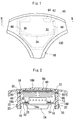
- a retainer 10 comprises a flat plate portion 14, to which an airbag 12 is attached, and a cover-mounting portion consisting of a side wall 16 extending from the edge of the flat plate portion 14 in a direction apart from an occupant.
- the airbag 12 in the folded state is covered by a module cover 18.
- the module cover 18 comprises a main plate portion 18A facing the occupant and a leg 18B extending from a side of the main plate portion 18A.
- the leg 18B is fixed to the side wall 16 of the retainer 10 by rivets 20.
- a metal patch is arranged along the leg 18B.
- An inflator 24 is fixed to the retainer 10 in such a manner that its upper portion is positioned inside the airbag 12 through an opening 26 formed in the flat plate portion 14.
- Numeral 28 designates an airbag-mounting member called as a ring.
- the periphery of the opening of the airbag 12 is clamped between ring 28 and the periphery of the opening 26 of the flat plate portion 14, whereby the airbag 12 is secured to the retainer 10.
- Fixed to the ring 28 are bolts not shown. The bolts are inserted into the bolt through holes formed in the periphery of the opening of the airbag 12, in the flat plate portion 14 of the retainer, and in a flange 24a of the inflator 24 and nuts are screwed onto the bolts, respectively.
- the main plate portion 18A of the module cover 18 includes tear lines 30, 32, 34 on the back thereof.
- the tear lines 30, 32 extend in the vertical direction of Fig. 1 along the leg 18B on the right side and the left side in Fig. 1.
- the tear line 34 extends in substantially the central portion of the main plate portion 18A in the lateral direction of Fig. 1 in such a manner as to connect the tear lines 30 and 32.
- the main plate portion 18A of the module cover is divided into two areas, which is to form flaps 40, 42, defined by the tear lines 30, 32, 34.
- flaps 40, 42 defined by the tear lines 30, 32, 34.
- a sheet switch 50 like a membrane for a vehicle horn is disposed in such a manner as to confront only the flap 40 positioned above in Fig. 1.
- Numeral 52 designates cables for the sheet switch 50.
- the switch 50 is supported by a plate 60 so that the membrane switch 50 is positioned between the supporting plate 60 and the main plate portion 18A (the flap 40) of the module cover.
- the plate 60 has bosses 61 as rivet inserts standing thereon.
- the bosses 61 are inserted into holes 55 of the sheet switch 50 and then riveted with heat, whereby the sheet switch 50 is fixed to the backing plate 60. Another means for fixing them may be employed.
- the backing plate 60 formed in a L-like shape comprises a main part 62 confronting the sheet switch 50 and a mounting arm 64 projecting or extending from the main part 62 in substantially the perpendicular direction.
- the mounting arm 64 extends along the leg 18B of the module cover 18 and is clamped between the leg 18B and the side wall 16 of the retainer 10. By driving rivets into rivet holes 70, 72 (Fig. 3) formed in both the leg 18B and the mounting arm 64 and the rivet holes (not shown) formed in the side wall 16, the mounting arm 64 is connected to the retainer 10.
- the main part 62 of the plate 60 is provided with projections 66, 66 extending toward the right and left of Fig. 1.
- the projections 66, 66 are engaged with openings 80, 80 of the leg 18B after passing over the tear lines 30, 32, respectively.
- the projections 66, 66 are in contact with the lower edges of the openings 80, 80. Therefore, when the main plate portion 18A of the module cover is depressed, the sheet switch 50 and the backing plate 60 are not moved backward so that the switch 50 is actuated.
- the openings 80, 80 of the leg 18B are positioned near the main plate portion 18A. Accordingly, the projections 66, 66 are disposed to project from the main part 62 in substantially the lateral direction. Since each projection 66 is cranked as shown in Fig. 2, the cranked portion can be easily deformed during the inflation of the airbag.
- the mounting arm 64 of the plate 60 is bent at a position near the main part 62 so that the main part 62 also opens toward the vehicle cabin together with the flap 40. At this point, also the projections 66, 66 bend and they come off the openings 80, 80.
- the plate 60 Since the main part 62 of the plate 60 confronts only the flap 40 and does not extend over the tear lines 30, 32, 34, the plate 60 never interferes the tearing of the module cover 18 along the tear lines 30, 32, 34. During the expansion of the airbag 12, the plate 60 bends only at the mounting arm 64 and the projections 66, 66 so as not to interfere the deployment of the airbag 12. Therefore, the inflator 24 is not required to have high pressure for generating gas.
- the leg 18B may be provided with recesses 99, 99 formed in the inner surface thereof instead of the openings 80, 80 as shown in Fig. 4.
- the sheet switch can be actuated by lightly depressing the module cover.
- the bag can be deployed at a predetermined speed without increasing the gas pressure of the inflator.
Landscapes
- Engineering & Computer Science (AREA)
- Mechanical Engineering (AREA)
- Air Bags (AREA)
Applications Claiming Priority (2)
| Application Number | Priority Date | Filing Date | Title |
|---|---|---|---|
| JP10117010A JPH11310099A (ja) | 1998-04-27 | 1998-04-27 | 運転席用エアバッグ装置 |
| JP11701098 | 1998-04-27 |
Publications (3)
| Publication Number | Publication Date |
|---|---|
| EP0953482A2 true EP0953482A2 (fr) | 1999-11-03 |
| EP0953482A3 EP0953482A3 (fr) | 2002-09-11 |
| EP0953482B1 EP0953482B1 (fr) | 2004-06-16 |
Family
ID=14701231
Family Applications (1)
| Application Number | Title | Priority Date | Filing Date |
|---|---|---|---|
| EP99107403A Expired - Lifetime EP0953482B1 (fr) | 1998-04-27 | 1999-04-26 | Coussin gonflable pour conducteur |
Country Status (4)
| Country | Link |
|---|---|
| US (1) | US6179325B1 (fr) |
| EP (1) | EP0953482B1 (fr) |
| JP (1) | JPH11310099A (fr) |
| DE (1) | DE69917985T2 (fr) |
Cited By (1)
| Publication number | Priority date | Publication date | Assignee | Title |
|---|---|---|---|---|
| WO2024105150A1 (fr) * | 2022-11-18 | 2024-05-23 | ZF Automotive Safety Germany GmbH | Unité de logement de module de coussin de sécurité gonflable, module de coussin de sécurité gonflable, et volant de direction |
Families Citing this family (15)
| Publication number | Priority date | Publication date | Assignee | Title |
|---|---|---|---|---|
| US6626458B2 (en) * | 2000-09-26 | 2003-09-30 | Toyoda Gosei Co., Ltd. | Steering wheel having airbag apparatus |
| US6581958B2 (en) * | 2001-04-17 | 2003-06-24 | Autoliv Asp, Inc. | Energy managed airbag cover |
| KR100559864B1 (ko) * | 2003-10-24 | 2006-03-13 | 현대자동차주식회사 | 자동차용 멤브레인 스위치의 장착구조 |
| US8921244B2 (en) * | 2005-08-22 | 2014-12-30 | The Procter & Gamble Company | Hydroxyl polymer fiber fibrous structures and processes for making same |
| US20070113600A1 (en) * | 2005-11-21 | 2007-05-24 | Marcelle Jesse A | Locking mechanism |
| US8852474B2 (en) * | 2007-07-17 | 2014-10-07 | The Procter & Gamble Company | Process for making fibrous structures |
| US20090022983A1 (en) | 2007-07-17 | 2009-01-22 | David William Cabell | Fibrous structures |
| US7972986B2 (en) | 2007-07-17 | 2011-07-05 | The Procter & Gamble Company | Fibrous structures and methods for making same |
| US10024000B2 (en) | 2007-07-17 | 2018-07-17 | The Procter & Gamble Company | Fibrous structures and methods for making same |
| EP2496768B1 (fr) * | 2009-11-02 | 2015-07-29 | The Procter and Gamble Company | Structures fibreuses à faible peluchage et procédés pour leur fabrications |
| EP2496738B1 (fr) * | 2009-11-02 | 2014-03-19 | The Procter and Gamble Company | Éléments fibreux en polypropylène et leurs procédés de fabrication |
| CA2779719C (fr) * | 2009-11-02 | 2014-05-27 | The Proctor & Gamble Company | Elements fibreux et structures fibreuses les employant |
| WO2011053677A1 (fr) * | 2009-11-02 | 2011-05-05 | The Procter & Gamble Company | Structures fibreuses et leurs procédés de fabrication |
| MX346871B (es) | 2010-03-31 | 2017-03-24 | Procter & Gamble | Estructuras fibrosas y métodos para elaborarlas. |
| US9694780B1 (en) * | 2016-03-17 | 2017-07-04 | Autoliv Asp, Inc. | Airbag cover with breakaway-resistant features |
Citations (2)
| Publication number | Priority date | Publication date | Assignee | Title |
|---|---|---|---|---|
| JPH08188109A (ja) | 1995-01-13 | 1996-07-23 | Nippon Plast Co Ltd | エアバッグ装置 |
| JPH0966793A (ja) | 1995-08-31 | 1997-03-11 | Nippon Plast Co Ltd | エアバッグ装置 |
Family Cites Families (6)
| Publication number | Priority date | Publication date | Assignee | Title |
|---|---|---|---|---|
| JPH0582709U (ja) * | 1992-04-13 | 1993-11-09 | 豊田合成株式会社 | エアバッグ装置のパッド |
| JP3163747B2 (ja) * | 1992-06-01 | 2001-05-08 | 豊田合成株式会社 | ステアリングホイールのパッド |
| US5265905A (en) * | 1993-01-07 | 1993-11-30 | Ford Motor Company | Air bag cover horn blow switch assembly |
| JP2766775B2 (ja) * | 1993-03-23 | 1998-06-18 | ティーアールダブリュー・ヴィークル・セーフティ・システムズ・インコーポレーテッド | ハウジング組立体及び装置 |
| JP3252169B2 (ja) * | 1993-04-27 | 2002-01-28 | 豊田合成株式会社 | ステアリングホイールのパッド |
| JP3639045B2 (ja) * | 1996-06-14 | 2005-04-13 | 日本プラスト株式会社 | エアバッグ装置 |
-
1998
- 1998-04-27 JP JP10117010A patent/JPH11310099A/ja active Pending
-
1999
- 1999-04-22 US US09/296,244 patent/US6179325B1/en not_active Expired - Fee Related
- 1999-04-26 DE DE69917985T patent/DE69917985T2/de not_active Expired - Fee Related
- 1999-04-26 EP EP99107403A patent/EP0953482B1/fr not_active Expired - Lifetime
Patent Citations (2)
| Publication number | Priority date | Publication date | Assignee | Title |
|---|---|---|---|---|
| JPH08188109A (ja) | 1995-01-13 | 1996-07-23 | Nippon Plast Co Ltd | エアバッグ装置 |
| JPH0966793A (ja) | 1995-08-31 | 1997-03-11 | Nippon Plast Co Ltd | エアバッグ装置 |
Cited By (1)
| Publication number | Priority date | Publication date | Assignee | Title |
|---|---|---|---|---|
| WO2024105150A1 (fr) * | 2022-11-18 | 2024-05-23 | ZF Automotive Safety Germany GmbH | Unité de logement de module de coussin de sécurité gonflable, module de coussin de sécurité gonflable, et volant de direction |
Also Published As
| Publication number | Publication date |
|---|---|
| DE69917985D1 (de) | 2004-07-22 |
| DE69917985T2 (de) | 2004-10-28 |
| EP0953482B1 (fr) | 2004-06-16 |
| JPH11310099A (ja) | 1999-11-09 |
| EP0953482A3 (fr) | 2002-09-11 |
| US6179325B1 (en) | 2001-01-30 |
Similar Documents
| Publication | Publication Date | Title |
|---|---|---|
| EP0953482B1 (fr) | Coussin gonflable pour conducteur | |
| US6386577B1 (en) | Side-collision air bag device | |
| US7232151B2 (en) | Airbag device | |
| US7766381B2 (en) | Steering wheel with air bag device | |
| US7104566B2 (en) | Airbag module and cover arrangement | |
| US5531471A (en) | Air bag and lid arrangement for vehicle | |
| JPH05208649A (ja) | 助手席用エアバッグ装置におけるケースとドアとの連結構造 | |
| EP0714816B1 (fr) | Couvercle de déploiement pour utilisation dans un dispositif de retenue d'un occupant de véhicule | |
| JP2513416Y2 (ja) | エアバッグ装置のリッド構造 | |
| JP2678208B2 (ja) | 自動車の助手席エアバッグ装置 | |
| JPH02171381A (ja) | ステアリングホイール | |
| JP2007196789A (ja) | 歩行者用エアバッグ装置 | |
| JPH05270338A (ja) | 助手席用エアバッグ装置のモジュールカバー取付構造 | |
| KR100471761B1 (ko) | 조수석 에어백 모듈의 에어백 도어 록킹구조 | |
| JPH08225049A (ja) | 助手席用エアバッグ装置 | |
| JPH10129385A (ja) | エアバッグ装置 | |
| JP3460880B2 (ja) | エアバッグ装置 | |
| JP2862785B2 (ja) | エアバッグユニット取付構造 | |
| JP3063753B1 (ja) | 助手席用エアーバッグ装置 | |
| JPH10244896A (ja) | エアバッグ装置 | |
| JP2004291727A (ja) | エアバッグリッド構造 | |
| JPH04303052A (ja) | 自動車のエアバッグ構造 | |
| JP2851029B2 (ja) | エアバッグユニット取付構造 | |
| JPH08295197A (ja) | エアバッグ装置 | |
| JP2004106822A (ja) | エアバッグ装置 |
Legal Events
| Date | Code | Title | Description |
|---|---|---|---|
| PUAI | Public reference made under article 153(3) epc to a published international application that has entered the european phase |
Free format text: ORIGINAL CODE: 0009012 |
|
| AK | Designated contracting states |
Kind code of ref document: A2 Designated state(s): AT BE CH CY DE DK ES FI FR GB GR IE IT LI LU MC NL PT SE |
|
| AX | Request for extension of the european patent |
Free format text: AL;LT;LV;MK;RO;SI |
|
| PUAL | Search report despatched |
Free format text: ORIGINAL CODE: 0009013 |
|
| AK | Designated contracting states |
Kind code of ref document: A3 Designated state(s): AT BE CH CY DE DK ES FI FR GB GR IE IT LI LU MC NL PT SE |
|
| AX | Request for extension of the european patent |
Free format text: AL;LT;LV;MK;RO;SI |
|
| 17P | Request for examination filed |
Effective date: 20021202 |
|
| AKX | Designation fees paid |
Designated state(s): DE GB |
|
| GRAP | Despatch of communication of intention to grant a patent |
Free format text: ORIGINAL CODE: EPIDOSNIGR1 |
|
| GRAS | Grant fee paid |
Free format text: ORIGINAL CODE: EPIDOSNIGR3 |
|
| GRAA | (expected) grant |
Free format text: ORIGINAL CODE: 0009210 |
|
| AK | Designated contracting states |
Kind code of ref document: B1 Designated state(s): DE GB |
|
| REG | Reference to a national code |
Ref country code: GB Ref legal event code: FG4D |
|
| REF | Corresponds to: |
Ref document number: 69917985 Country of ref document: DE Date of ref document: 20040722 Kind code of ref document: P |
|
| REG | Reference to a national code |
Ref country code: IE Ref legal event code: FG4D |
|
| PLBE | No opposition filed within time limit |
Free format text: ORIGINAL CODE: 0009261 |
|
| 26N | No opposition filed |
Effective date: 20050317 |
|
| PGFP | Annual fee paid to national office [announced via postgrant information from national office to epo] |
Ref country code: DE Payment date: 20080502 Year of fee payment: 10 |
|
| PGFP | Annual fee paid to national office [announced via postgrant information from national office to epo] |
Ref country code: GB Payment date: 20080430 Year of fee payment: 10 |
|
| GBPC | Gb: european patent ceased through non-payment of renewal fee |
Effective date: 20090426 |
|
| PG25 | Lapsed in a contracting state [announced via postgrant information from national office to epo] |
Ref country code: DE Free format text: LAPSE BECAUSE OF NON-PAYMENT OF DUE FEES Effective date: 20091103 |
|
| PG25 | Lapsed in a contracting state [announced via postgrant information from national office to epo] |
Ref country code: GB Free format text: LAPSE BECAUSE OF NON-PAYMENT OF DUE FEES Effective date: 20090426 |