EP1035258A1 - Baumaschine mit einem fahrerhaus - Google Patents
Baumaschine mit einem fahrerhaus Download PDFInfo
- Publication number
- EP1035258A1 EP1035258A1 EP99925284A EP99925284A EP1035258A1 EP 1035258 A1 EP1035258 A1 EP 1035258A1 EP 99925284 A EP99925284 A EP 99925284A EP 99925284 A EP99925284 A EP 99925284A EP 1035258 A1 EP1035258 A1 EP 1035258A1
- Authority
- EP
- European Patent Office
- Prior art keywords
- cab
- frame
- vibrational
- mounting plate
- operator
- Prior art date
- Legal status (The legal status is an assumption and is not a legal conclusion. Google has not performed a legal analysis and makes no representation as to the accuracy of the status listed.)
- Granted
Links
Images








Classifications
-
- B—PERFORMING OPERATIONS; TRANSPORTING
- B62—LAND VEHICLES FOR TRAVELLING OTHERWISE THAN ON RAILS
- B62D—MOTOR VEHICLES; TRAILERS
- B62D33/00—Superstructures for load-carrying vehicles
- B62D33/06—Drivers' cabs
- B62D33/0604—Cabs insulated against vibrations or noise, e.g. with elastic suspension
- B62D33/0608—Cabs insulated against vibrations or noise, e.g. with elastic suspension pneumatic or hydraulic suspension
-
- E—FIXED CONSTRUCTIONS
- E02—HYDRAULIC ENGINEERING; FOUNDATIONS; SOIL SHIFTING
- E02F—DREDGING; SOIL-SHIFTING
- E02F9/00—Component parts of dredgers or soil-shifting machines, not restricted to one of the kinds covered by groups E02F3/00 - E02F7/00
- E02F9/16—Cabins, platforms, or the like, for drivers
- E02F9/166—Cabins, platforms, or the like, for drivers movable, tiltable or pivoting, e.g. movable seats, dampening arrangements of cabins
-
- B—PERFORMING OPERATIONS; TRANSPORTING
- B62—LAND VEHICLES FOR TRAVELLING OTHERWISE THAN ON RAILS
- B62D—MOTOR VEHICLES; TRAILERS
- B62D33/00—Superstructures for load-carrying vehicles
- B62D33/06—Drivers' cabs
- B62D33/0604—Cabs insulated against vibrations or noise, e.g. with elastic suspension
-
- E—FIXED CONSTRUCTIONS
- E02—HYDRAULIC ENGINEERING; FOUNDATIONS; SOIL SHIFTING
- E02F—DREDGING; SOIL-SHIFTING
- E02F3/00—Dredgers; Soil-shifting machines
- E02F3/04—Dredgers; Soil-shifting machines mechanically-driven
- E02F3/28—Dredgers; Soil-shifting machines mechanically-driven with digging tools mounted on a dipper- or bucket-arm, i.e. there is either one arm or a pair of arms, e.g. dippers, buckets
- E02F3/30—Dredgers; Soil-shifting machines mechanically-driven with digging tools mounted on a dipper- or bucket-arm, i.e. there is either one arm or a pair of arms, e.g. dippers, buckets with a dipper-arm pivoted on a cantilever beam, i.e. boom
- E02F3/308—Dredgers; Soil-shifting machines mechanically-driven with digging tools mounted on a dipper- or bucket-arm, i.e. there is either one arm or a pair of arms, e.g. dippers, buckets with a dipper-arm pivoted on a cantilever beam, i.e. boom working outwardly
Definitions
- This invention relates generally to a construction machine with an operator's cab, for example, a hydraulic excavators, a hydraulic crane and the like, and more particularly to a construction machine which has an operator's cab supported on a frame of the machine in a vibration damped state.
- a hydraulic excavators as a construction machine with an operator's cab is largely constituted by a truck body, a rotary upper body which is rotatably mounted on the truck body, and a working mechanism which is provided on the upper rotary body for upward and downward lifting movements.
- an operator's cab which accommodates control instruments and devices to be manipulated by an operator in controlling operations the truck body and working mechanism, and an operator's seat to be occupied by an operator.
- Japanese Laid-Open Patent Publication No. H5-125745 discloses a hydraulic excavator having an operator's cab mounted on a support frame in a vibration damped state, by the use of anti-vibrational mounts in the form of liquid-sealed rubber mounts which are interposed in four corner portions between the support frame and the operator's cab in an attempt to suppress transmission of vibrations from the frame to the cab during a ground excavating operation or when the machine is in travel.
- the large-size hydraulic excavators which are used, for example, in excavating a large quantity of earth at open mining sites are usually constructed in a different concept. Namely, in the construction of large-size hydraulic excavators, there has been a trend toward giving top priority to the machine durability rather than the amenity of the operator's cab because, in case of a machine trouble, a repair work could take enormously long time. For this reason, usually little attention is paid to the amenity of the operator's cab in the construction of large-size hydraulic excavators.
- a vertical or upright bed frame is provided on a main frame which constitutes a bottom portion of a rotary body, and an operator's cab is mounted on top of the bed frame.
- the operator's cab is located in a position which is largely spaced away from a truck body in an upward direction, and vibrations which occur when the machine is in travel or which occur during an excavating operation are transmitted to the cab through the bed frame, thereby putting the cab in conspicuous vibrational movements.
- a cab support which is applicable to a construction machine with an operator's cab, basically including a support frame, an operator's cab mounted on the support frame and internally defining an operating room, and four anti-vibrational mounts interposed in four corner portions between the support frame and the cab and adapted to support the cab in such a manner as to suppress transmission of vibrations from the frame to the cab.
- a construction machine with an operator's cab which is characterized by the provision of: four anti-vibrational mounts each constituted by a laminated rubber body having relatively high rigidity against vibration in a vertical direction and relatively low rigidity against vibration in a horizontal direction; and four vibration attenuating devices located in four corner portions between the frame and cab and in cooperative positions relative to the anti-vibrational mounts to attenuate horizontal vibrations transmitted to the cab.
- the laminated rubber bodies of the respective anti-vibrational mounts are caused to flex largely in a horizontal direction, thereby suppressing transmission of vibration from the frame to the cab.
- the cab is simply put in horizontal parallel movements and prevented from being shaken largely by pitching or rolling vibrations because the laminated rubber bodies of the anti-vibrational mounts have high rigidity against vibrations in vertical directions.
- horizontal residual vibrations occur to the cab due to resilient restoring forces of the laminated rubber bodies which are flexed by vibrations of the frame, such residual vibrations can be damped by the respective vibration attenuating devices.
- two of the vibration attenuating devices which are located in front portions of the cab, are mounted in a horizontal plane and in an angular posture such that respective longitudinal axes are intersected with each other on the front side of the cab, while the remaining two vibration attenuating devices, which are located in rear portions of the cab, are likewise mounted in a horizontal plane and in an angular posture such that respective longitudinal axis are intersected with each other on the rear side of the cab.
- each one of the vibration attenuating devices according to the present invention is so arranged as to have a longitudinal axis thereof located in a circumscribing position relative to an imaginary ellipse drawn around a bottom center portion of the cab.
- the respective vibration attenuating devices are mounted in a horizontal plane and in an angular posture which is inclined relative to back and forth and transverse directions of the cab. Therefore, when the cab is put in vibrations in back and forth directions or in lateral directions, these vibrations can be effectively damped by the vibrations attenuating devices. Further, the vibration attenuating devices also function to effectively suppress yawing movements which may occur to the cab as a result of a rotational movement.
- the frame is a main frame constituting a bottom portion of a rotary body of the machine, and the cab is supported on the main frame through the anti-vibrational mounts.
- the frame is composed of a main frame constituting a bottom portion of a rotary body of the machine and a bed frame standing vertically on the main frame, and the cab is supported on the bed frame through the anti-vibrational mounts.
- the respective anti-vibrational mounts function to suppress transmission of vibrations from the frame to the cab through the bed frame, thereby preventing the cab from being largely shaken on the bed frame.
- each one of the anti-vibrational mounts is constituted by a laminated rubber body having a plural number of rubber layers laminated alternately and in parallel relation with a plural number of thin steel sheet layers, an upper mounting plate securely fixed to upper end of the laminated rubber body, and a lower mounting plate securely fixed to lower end of the laminated rubber body.
- each anti-vibrational mounts are securely fastened to each other by the use of bolts, and stud bolts are fixedly provided either on the side of the cab or on the side of the upper mounting plate of the anti-vibrational mounts and adapted to be received in bolt holes provided either on the side of the upper mounting plate or on the side of the cab.
- the cab can be automatically set in position relative to the anti-vibrational mounts simply by fastening the lower mounting plates of the anti-vibrational mounts securely to the frame by means of bolts and inserting the stud bolts, which are provided either on the side of the upper mounting plates of the anti-vibrational mounts or on the side of the cab, into bolt holes which are provided opposingly either on the side of the cab or on the side of the upper mounting plates of the anti-vibrational mounts.
- each anti-vibrational mounts are securely fastened to each other by the use of bolts, and stud bolts are fixedly provided either on the side of the frame or on the side of the lower mounting plate of the anti-vibrational mounts and adapted to be received in bolt holes provided either on the side of the lower mounting plate or on the side of the frame.
- each one of the anti-vibrational mounts can be automatically set in position relative to the frame, upon inserting the stud bolts, which are provided either on the side of the lower mounting plates of the anti-vibrational mounts or on the side of the frame, into bolt holes which are provided opposingly either on the side of the frame or on the side of the lower mounting plates of the anti-vibrational mounts.
- stud bolts are fixedly provided in the lower mounting plate of each anti-vibrational mounts and adapted to be received in bolt holes provided in the frame, and stud bolts are fixedly provided in the upper mounting plate of the anti-vibrational mounts and adapted to be received in bolt holes provided on the part of the cab.
- the respective ones of the anti-vibrational mounts can be automatically set in position relative to the frame and the cab, upon inserting stud bolts, which are provided on the lower and upper mounting plates of the anti-vibrational mounts, into bolt holes which are provided opposingly on the side of the frame and the cab, respectively.
- the frame and the lower mounting plate of each anti-vibrational mount are securely fastened to each other by the use of bolts, and an intermediate connecting plate is attached to the upper mounting plate of the anti-vibrational mount, the intermediate connecting plate having stud bolts adapted to be received in bolt holes provided on the part of the cab.
- each of the anti-vibrational mounts which have the respective lower mounting plates fastened to the frame by means of bolts, can be automatically set in position relative to the cab upon inserting the stud bolts on the intermediate connecting plate, which is attached to the upper mounting plate of each anti-vibrational mount, into bolt holes which are provided opposingly on the side of the cab.
- it can be easily extracted in a horizontal direction as soon as the upper mounting plate is removed from the intermediate connecting plate, without being obstructed by the stud bolts.
- the cab and the upper mounting plate of each anti-vibrational mounts are securely fastened to each other by the use of bolts, and an intermediate connecting plate is attached to the lower mounting plate of the anti-vibrational mount, the intermediate connecting plate having stud bolts adapted to be received in bolt holes provided on the side of the frame.
- the anti-vibrational mounts can be automatically set in position relative to the frame, upon inserting the stud bolts of the intermediate connecting plate, which is attached to the lower mounting plate of each anti-vibrational mounts, into bolt boles which are provided opposingly on the side of the frame. Besides, in this case, at the time of replacement of an anti-vibrational mount, it can be easily extracted in a horizontal direction after detaching the lower mounting plate from the intermediate connecting plate, without being obstructed by the stud bolts.
- a crawler type truck body and at 2 is a rotary body which is rotatably mounted on the truck body 1.
- a loader bucket type working mechanism 3 for upward and downward lifting movements.
- Denoted at 4 is a main frame which constitutes a bottom portion of the rotary body 2.
- This main frame 4 has a frame structure which extends in a horizontal direction, and a vertically standing bed frame 5 is set on a front left portion of the main frame.
- the rotary body 2 is largely constituted by the above-mentioned main frame 4 and bed frame 5, along with an operator's cab 13 which is located on the bed frame 5 as will be described hereinafter, a housing 6 which is located on a rear portion of the bed frame 5 to accommodate a prime mover (not shown) etc., and a counterweight 7 attached to a rear portion of the main frame 4 at a position behind the housing 6.
- the bed frame 5 is constituted by: a box-like outer frame structure 8 which is enclosed by front plate 8A, rear plate 8B and right and left side plates 8C and is open on the top side thereof; a cab support plate 9 in the form of a horizontally extended rectangular frame structure which is located in an inner upper portion of the outer frame structure 8 and provided with mount member fixing portions 9A in its four corner portions to support the cab 13 through anti-vibrational mounts 18 which will be described hereinafter; and vertically extending reinforcing members 10 which are attached to the lower side of the mount member fixing portions 9A for the purpose of reinforcing the cab support plate 9.
- the bed frame 5 is erected on the main frame 4.
- brackets 11 are securely fixed to the front and rear plates 8A and 8B of the outer frame structure 8 by welding or other suitable means, symmetrically in the back and forth and transverse directions of the machine.
- a mounting seats 12 for supporting lower ends of the anti-vibrational mounts 18 are securely welded or fixed to top surfaces of the mount member fixing portions 9A of the cab support plate 9.
- a cab which is located on the bed frame 5 to define an operating room for the operator.
- the cab 13 is in the form of a box-like enclosure having a top side section 13A, a front side section 13B, a rear side section 13C and left and right side sections 13D (only one of which is shown in the drawings) and formed, for example, by welding together thin press-formed steel plates.
- brackets 13E for a flooring plate is securely fixed by welding to inner lower portions of the cab 13, and a floor panel 14 is fixedly bolted to the brackets 13E to form a bottom of the cab 13.
- An operator's seat to be seated by an operator is provided internally of the cab 13 along with control levers and instruments ( both not shown) for operating the working mechanism 3.
- four mounting seats 15 are securely welded to the lower side of the floor panel 14 for the purpose of supporting upper ends of the anti-vibrational mounts 18.
- four brackets 16 on the side of the cab are securely fixed to the lower side of the floor panel 14 by welding or by other suitable means symmetrically in back and forth and transverse directions of the machine.
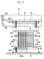
- Indicated at 17 are four stud bolts (only two stud bolts are shown in the drawing) which are projected downward through the mounting seats 15 on the side of the cab 13. As shown in Fig. 5, these stud bolts 17 are passed through bolt passage holes 21A which are bored in an upper mounting plates 21 the anti-vibrational mounts 18 as will be described hereinbelow.
- Denoted at 18 are the anti-vibrational mounts which are located at position in four corner portions and between the floor panel 14 of the cab 13 and the bed frame 5. These anti-vibrational mounts 18 are each constituted by a lower mounting plate 19, an upper mounting plate and laminated rubber 23, which will be described hereinafter.
- the lower mounting plate 19 is attached to a mounting seat 12 on the side of the bed frame 5, and constituted by a rectangular steel plate with bolt passage holes 19A bored in four corner portions thereof. Further, the lower mounting plate 19 is fastened to the mounting seat 12 by a bolt 20 which is passed through the bolt passage hole 19A.
- the upper mounting plate 21 is attached to a mounting seat 15 on the side of the cab 13, and similarly constituted by a rectangular steel plate with bolt passage holes 21A bored in four corner portions thereof. Further, the upper mounting plate 21 is fastened to a mounting seat 15 by threading and tightening a nut 22 onto a stud bolt 17 which is projected from the mounting seat 15 on the part of the cab 13 and passed through the bolt passage hole 21A.
- the laminated rubber body 23 which is interposed between the upper and lower mounting plates 21 and 19, is constituted by a plural number of laminated resilient rubber layers 23A, and thin steel sheet layers 23B which are interposed alternately and parallel with the resilient rubber layers 23A.
- the top and bottom sides of the laminated rubber body 23 are securely fixed to the upper and lower mounting plates 21 and 19 by welding or by the use of an adhesive, respectively.
- the laminated rubber body 23 which is formed by laminating a plural number of rubber sheets 23A alternately with a plural number of steel sheets 23B, has relatively high rigidity against vibrations of vertical directions, because the thin steel sheets 23B act to prevent flexure of the rubber layers 23A when a load is applied thereon from or in a vertical direction.
- the laminated rubber body 23 has relatively low rigidity against vibrations of horizontal directions, because the resilient rubber layers 23A between the thin steel sheets 23B are allowed to flex to a relatively large degree when a load is applied thereto from or in a horizontal direction, for example, from a lateral, front or rear side of the laminated rubber body 23.
- each one of the anti-vibrational mounts 18 with the laminated rubber body 23 functions to suppress vibrational movements of the cab 13 particularly in the back and forth direction (hereinafter referred to as "pitching" for brevity), in the lateral direction (hereinafter referred to as “rolling” for brevity) and in the vertical direction (hereinafter referred to as “bouncing” for brevity), thereby supporting the cab 13 in a quite stabilized state.
- the laminated rubber bodies 23 which have relatively high rigidity in the vertical direction function translate the vibration of the cab 13 into horizontal parallel movements and prevent pitching and rolling movements of the cab 13.
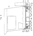
- each one of the oil dampers 24 is composed of a tube 25 having a piston (not shown) slidably fitted therein, and a piston rod 26 which is connected at its base or inner end to the piston within the tube 25 and projected out of the tube 25 at the other outer end. Attenuating force is produced by each oil damper 24 as the piston is reciprocated within the tube 25 against resistance of oil. Further, a mounting eye 25A is securely fixed to the base end of the tube 25 of each oil damper, and a mounting bolt 26A is securely fixed to the fore projected end of the piston rod 26. The piston rod 26 is covered with a dust cover 26B.
- each oil damper 24 is secured resiliently through a rubber bush 27 to a bracket 11 on the side of the frame, which is securely fixed to the outer frame structure 8 of the bed frame 5.
- the mounting bolt 26A at the base end of the piston rod 26 is secured resiliently through a cushioning rubber member 28 to a bracket 16 on the side of the cab 13, which is securely fixed to the lower side of the floor panel 14. Consequently, the oil dampers 24 are arranged to connect the bed frame 5 and the floor panel 14 of the cab 13 with each other.
- the longitudinal axes O-O of the oil dampers 24 which are located in a left front portion and in a right front portion of the floor panel 14 are intersected with each other on the front side of the floor panel 14 and with an inclination angle ⁇ relative to back and forth direction X-X of the floor panel 14.
- the longitudinal axis O-O of the oil dampers 24 which are located in a left rear portion and in a right rear portion of the floor panel 14 are intersected with each other on the rear side of the floor panel and with an inclination angle ⁇ relative to the back and forth direction of the floor panel 14.
- the respective oil dampers 24 are mounted in an inclined angular posture or position such that the longitudinal axes O-O of the oil dampers 24 circumscribe an imaginary ellipse S (indicated by two-dot chain line in Fig. 3) which is drawn on a horizontal plane at and around a center portion of the floor panel 14.
- the inclination angle ⁇ of each oil damper 24 is determined on the basis of a ratio of attenuation force A, which is necessary for attenuation of vibration of the cab 13 in back and forth directions, to attenuation force B which is necessary for attenuation of vibration in lateral directions.
- a method of computing the inclination angle ⁇ of the oil dampers 24 is described below with reference to Fig. 6.
- V1 is the velocity of movement of the cab 13 when in vibration in back and forth direction
- V1' V1 cos ⁇
- V2 is the velocity of movement of the cab 13 when in vibration in lateral direction
- V2' V2 sin ⁇
- Equation 5 a component F2 in lateral direction of the attenuation force F is expressed by following Equation 5.
- F2 F sin ⁇
- Equation 6 a component C1 in back and forth direction of the attenuation coefficient C is expressed by following Equation 6.
- Equation 7 a component C2 in lateral direction of the attenuation coefficient C is expressed by following Equation 7.
- a total attenuation coefficient C1t in the back and forth direction which is a sum of attenuation coefficients C1 of the four oil dampers in the back and forth direction, is expressed by following Equation 8.
- Equation 9 a total attenuation coefficient C2t in lateral direction, which is a sum of attenuation coefficients C2 of the four oil dampers in lateral direction, is expressed by following Equation 9.
- C2t 4C sin 2 ⁇
- a ratio of attenuation force A which is necessary for attenuation of vibration of the cab 13 in back and forth direction, to attenuation force B which is necessary for attenuation of vibration in lateral direction can be expressed as a ratio of the total attenuation coefficient C1t in back and forth direction to the total attenuation coefficient C2t in the lateral direction, as in following Equation 10.
- C1t : C2t A : B
- the inclination angle ⁇ of the respective oil dampers 24 can be expressed by way of the attenuation force A necessary for attenuation of vibration of the cab 13 in back and forth direction and the attenuation force B necessary for attenuation of vibration in lateral direction, as in following Equation 13.
- ⁇ cos -1 A /( A + B )
- the inclination angle ⁇ of the oil dampers 24 is determined according to the attenuation force A which is necessary for attenuation of vibrations of the cab 13 in a back and forth direction and the attenuation force B which is necessary for attenuation of vibrations in a lateral direction.
- the hydraulic excavator with the above-described arrangements according to the present embodiment, can effectively damp vibrations of the cab 13 which is mounted on the hydraulic excavator, in the manner as described below.
- the laminated rubber bodies of the anti-vibrational mounts 18 which have high rigidity against vibrations in vertical directions function to translate the vibrations into horizontal parallel movements. Therefore, the cab 13 is prevented from being largely shaken by pitching to ensure improved amenity within the cab 13 as well as improved maneuverability of control levers.
- the laminated rubber bodies 23 of the anti-vibrational mounts 18 are flexed between the bed frame 4 and the floor panel 14 of the cab 13, thereby to prevent direct transmission of vibration from the bed frame 5 to the cab 13 and to suppress vibrational movements of the cab 13.
- the laminated rubber bodies 23 of the anti-vibrational mounts 18 which have relatively high rigidity in the vertical direction function translate the vibrations into horizontal parallel movements of the cab 13. Therefore, the cab 13 is prevented from being shaken largely by rolling vibrations to ensure improved amenity within the cab 13.
- the laminated rubber bodies 23 of the anti-vibrational mounts 18 which have high rigidity in the vertical direction function prevent inclinations of the cab 13 on the bed frame 5 even when the vehicle body is inclined on a slope, for example, always maintaining the cab 13 in a horizontal state relative to the bed frame 5.
- each one of the oil dampers 24 is mounted in a horizontal plane and in an inclined posture at a certain inclination angle ⁇ from the back and forth direction of the cab 13. Therefore, despite the use of oil dampers 24 of the same type, adjustments can be made of the attenuation force against residual vibrations in the back and forth direction of the cab 13 as well as of the attenuation force against residual vibrations in lateral directions, by suitably varying the inclination angle ⁇ .
- the anti-vibrational mounts 18 which support the cab 13 on the bed frame 5 are each constituted by the laminated rubber body 23 which is arranged to have high rigidity against vibrations in vertical directions but to have low rigidity against vibrations in lateral directions.
- These characteristics of the laminated rubber bodies 23 prevent the cab 13 from being shaken to a considerable degree by pitching and rolling vibrations, and contribute to improve the amenity of the operator's cab 13 as well as the maneuverability of control levers or other instruments in the cab 13.
- the oil dampers 24 are provided in the four corner portions between the bed frame 5 and the floor panel 14 of the cab 13. Therefore, even if residual vibrations occur to the cab 13 under the influence of restoring forces of the laminated rubber bodies 23 which constitute the anti-vibrational mounts 18, such residual vibrations can also be attenuated by the oil dampers 24.
- the oil dampers 24 thus prevent the phenomenon of resonance which might otherwise occur to the cab 13 under the influence of residual vibrations, thereby improving the amenity of the cab 13 all the more.
- the present embodiment is particularly arranged to facilitate the job of assembling the cab 13 on the bed frame 5 through the anti-vibrational mounts 18, as described below with reference to Fig. 5.
- the lower mounting plates 19 of the anti-vibrational mounts 18 are fastened by bolts 20 to the mounting seats 12 which are securely fixed on the upper side of the cab support plate 9. Then, the cab 13 is lifted up by the use of a crane or the like (not shown) to a position where the mounting seats 15 on the lower side of the floor panel 14 of the cab 13 face the corresponding upper mounting plates 21 of the anti-vibrational mounts 18.
- the cab 13 is lowered until the mounting seats 15 on the side of the cab 13 come into abutting engagement with the upper mounting plates 21 of the anti-vibrational mounts 18.
- the stud bolt 17 which is projected downward from each mounting seat 15 can be easily threaded into the bolt hole 21A of an opposing upper mounting plate 21 when the cab 13 is lowered toward the anti-vibrational mounts 18.
- the nuts 22 are threaded onto the stud bolts 17 which are projected downward on the lower side of the upper mounting plates 21 through the bolt holes 21A, thereby fastening the upper mounting plates 21 of the respective anti-vibrational mounts 18 to the floor panel 14 of the cab 13.
- the cab 13 is mounted on the cab support plate 9 of the bed frame 5 through the anti-vibrational mounts 18.
- the cab 13 is automatically brought into a correct position relative to the anti-vibrational mounts 18 upon passing the stud bolts 17 on the lower side of the floor panel 14 of the cab 13 through the bolt holes 21A in the upper mounting plates 21 of the anti-vibrational mounts 18.
- the cab 13 can be assembled and mounted in position quite easily and efficiently, freeing the workers from a danger of getting a finger or fingers pinched between the cab and an anti-vibrational mount, as often experienced, for example, in the case of the prior art in which requires to insert fastening bolts into bolt holes while holding bolt holes on the side of a cab, which is lifted up by a crane, in matching positions relative to bolt, holes on the side of anti-vibrational mounts.
- a second embodiment of the present invention which is characterized in that, directly through the anti-vibrational mounts, the cab is supported on a main frame which constitutes a bottom portion of a rotary body to provide an ordinary type hydraulic excavator instead of a high mount type.
- a main frame which constitutes a bottom portion of a rotary body to provide an ordinary type hydraulic excavator instead of a high mount type.
- the main frame 31 includes a center frame 32 which is mounted on a rotational mechanism (not shown), and, in place of the bed frame 5 of the foregoing first embodiment, a cab support structure 33 is provided on a left front portion center frame 32.
- the center frame 32 is constituted by thick steel plates, including a bottom plate 32A and a pair of vertical or upright plates which are extended on and along the bottom plate 32A in the back and forth direction of the machine.
- the cab support 33 is largely constituted by a cross beam 33A of U-shape in section which is extended transversely across a front portion of the center frame 32, a rear frame 33B of L-shape in section which is extended in the transverse direction on the rear side of the cross beam 33A, a side frame 33C which is extended in the back and forth direction and securely connected to left ends of the cross beam 33A and rear frame 33B, a longitudinal beam 33D which is extended in the longitudinal direction from a right end of the cross beam 33A in parallel relation with the side frame 33C, and a front frame 33E of L-shape in section which is extended in the transverse direction and arranged to connect front ends of the side frame 33C and longitudinal beam 33D with each other.
- seat members 34 each of L-shape in section are securely fixed to the rear frame 33B and front frame 33E of the cab support 33.
- An anti-vibrational mount 18 is mounted between each seat member 34 and the floor panel 14 of the cab 13 to support the cab 13 resiliently on the main frame 31.
- brackets 11 in total are securely fixed to the rear and front frames 33B and 33E of the cab support 33, for example, by welding in symmetrical positions in the back and forth and transverse directions.
- oil dampers 24 are mounted in positions between these brackets 11 on the side of the frame and four brackets 16 which are securely fixed to the lower side of the floor panel 14 of the cab 13, so that the main frame 31 and the floor panel 14 of the cab 13 are connected with each other through the oil dampers 24.
- the oil dampers 24 of this embodiment are similarly arranged in angular positions. Namely, the oil dampers 24 in a left front portion and in a right front portion of the cab 13 are arranged in such angular positions that their longitudinal axes O-O are intersected with each other on the front side of the cab 13 with an inclination angle ⁇ from the back and forth direction X-X. On the other hand, the oil dampers 24 in a left rear portion and in a rear right portion of the cab 13 are arranged in such angular positions that their longitudinal axis O-O are intersected with each other on the rear side of the cab 13 with an inclination angle ⁇ from the back and forth direction X-X.
- the laminated rubber bodies 23 of the anti-vibrational mounts 18 are caused to flex between the main frame 31 and the floor panel 14 of the cab 13 to prevent direct transmission of the vibration from the main frame 31 to the cab 13, thereby suppressing vibrations of the cab 13.
- the anti-vibrational mounts 18 prevent the cab 13 from being largely shaken by pitching or rolling vibrations, thereby improving the amenity of the cab 13 as well as the maneuverability of control levers within the cab 13.
- the oil dampers 24 which are interposed between the main frame 31 and the floor panel 14 of the cab 13 to preclude the phenomenon of resonance which might occur as a result of the residual vibrations.
- a third embodiment of the present invention which is characterized in that the stud bolts which fasten the anti-vibrational mounts to the cab are provided on the part of the upper mounting plates of the anti-vibrational mounts.
- those component parts which are common with the foregoing first embodiment are simply designated by common reference numerals or characters to avoid repetitions of same explanations.
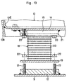
- a floor panel of the cab 13 which is bored with a plural number of bolt holes 41A (only two of which are shown in the drawing) to receive stud bolts which are provided on the part of the anti-vibrational mounts 18 as will be described hereinbelow.
- Each mounting seat 42 is bored with four bolt holes 42A in axially aligned relation with the bolt holes 41A in the floor panel 41.
- Indicated at 43 are two of four stud bolts which are securely fixed to the upper mounting plates 21 of the anti-vibrational mounts 18. Each one of these stud bolts 43 is planted in an upright position and adapted to be passed through the bolt hole 42A in the mounting seat 42 and the bolt hole 41A in the floor panel 41.
- the cab 13 is mounted on the cab support plate 9 through the anti-vibrational mounts 18 in the manner as follows.
- the lower mounting plates 19 of the anti-vibrational mounts 18 are fastened to the mounting seat 12 of the cab support plate 9 by the use of bolts 20, and then the cab 13 is lifted up by the use of a crane or the like (not shown) to bring the mounting seats 42 on the lower side of the floor panel 41 into face to face relation with the upper mounting plates 21 of the anti-vibrational mounts 18.
- the cab 13 is lowered to receive the stud bolts 43 on the anti-vibrational mounts 18 in the bolt holes 42A and 41A in the mounting seats 42 and the floor panel 41, respectively, and the cab 13 is fixed on the cab support plate 9 through the anti-vibrational mounts 18 by threading and tightening the nuts 44 onto the upper ends of the stud bolts 43 which are projected on the upper side of the floor panel 41 through the bolt holes 41A.
- the cab 13 as the cab 13 is lowered onto the anti-vibrational mounts 18, it can be automatically set in a predetermined position relative to the anti-vibrational mounts 18 in a safe and facilitated manner upon inserting the stud bolts 43 into the bolt holes 41A and 42A in the floor panel 41 and the mounting seats 42.
- a fourth embodiment of the present invention which is characterized in that an intermediate connecting plate with stud bolts is attached to the upper mounting plate of the anti-vibrational mount.
- those component parts which are common with the foregoing first embodiment are designated by common reference numerals or characters to avoid repetitions of same explanations.
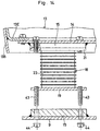
- FIG. 51 Indicated at 51 in that figure is a floor panel of the cab 13. Opened in the floor panel 51 is a plural number of bolt holes 51A (only two of which are shown in the drawing) for receiving stud bolts 54, which will be described hereinafter.
- Designated at 52 is an intermediate connecting plate which is fixed to the top side of the upper mounting plate 21 of the anti-vibrational mount 18 by means of four bolts 53 (only two of which are shown in the drawing).
- Four upright stud bolts 54 (only two of which are shown in the drawing) are planted in the intermediate connecting plate 52. These stud bolts 54 are projected upward through the bolt holes 51A in the floor panel 51 of the cab.
- the intermediate connecting plate 52 is attached to the upper mounting plate 21 of each anti-vibrational mount 18 by means of the bolts 53, and the lower mounting plate 19 of each anti-vibrational mount 18 is fastened to the mounting seat 12 of the cab support plate 9 by means of the bolts 20.
- the cab 13 is lifted down by the use of a crane or the like (not shown) to receive the stud bolts 54 of the respective intermediate connecting plates 52 in the bolt holes 51A in the floor panel 51 of the cab 13, and the nuts 55 are threaded and tightened onto the upper ends of the stud bolts 54 which are respectively projected on the upper side of the floor panel 51 through the bolt holes 51A.
- the cab 13 is mounted on the cab support plate 9 through the anti-vibrational mounts 18.
- the cab 13 as the cab 13 is lowered onto the anti-vibrational mounts 18, it can also be automatically brought into a predetermined position relative to the anti-vibrational mounts 18 in a safe and facilitated manner upon inserting the stud bolts 54 of the intermediate connecting plates 52 into the bolt holes 51A in the floor panel 51 of the cab 13.
- the anti-vibrational mounts 18 when one of the anti-vibrational mounts 18 is damaged and should be removed for replacement, it can be extracted easily in a horizontal direction after removing the bolts 20 and 53 from the lower and upper mounting plates 19 and 21 of the anti-vibrational mount 18. Therefore, a damaged anti-vibrational mount can be replaced quite easily, without entailing any troublesome job, for example, a job of lifting up the cab 13 for extracting the stud bolts 54 out of the bolt holes 51A of the floor panel 51.
- the stud bolts 17 are shown as being provided on the mounting seats 15 which are securely fixed on the lower side of the floor panel 14 of the cab 13.
- the present invention is not restricted to this particular arrangement.
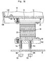
- arrangements may be made to insert bolts 61 downward from the upper side of the floor panel 14 and through the mounting seat 15 and to use as stud bolts the lower end portions of the bolts 61 which are projected downward on the lower side of the mounting seat 15.
- the stud bolts 17 are shown by way of example as being provided on the mounting seat 15 which is securely fixed to the lower side of the floor panel 14.
- the present invention is not restricted to this particular arrangement.
- the stud bolts 17 may be fixedly planted in the mounting seat 12 which is fixed on the upper side of the cab support plate 9.
- the stud bolts 17 may be provided on each one of the mounting seats 12 and 15 if desired.
- the stud bolts 43 are shown by way of example as being fixedly planted in the upper mounting plate 21 of the anti-vibrational mount 18.
- the present invention is not restricted to this particular arrangement.
- the stud bolts 43 may be fixed in the lower mounting plate 19 of the anti-vibrational mount 18 if desired.
- the stud bolts 43 may be fixed in the upper and lower mounting plates 18 and 19 of the anti-vibrational mount 18 if desired.
- the intermediate connecting plate 52 is shown by way of example as being attached to the upper mounting plate 21 of the anti-vibrational mount 18.
- the present invention is not restricted to this particular arrangement.
- the present invention has been described in connection with a particular type of construction machine.
- the present invention is not restricted to the particular type shown, and can be similarly applied to other construction machines such as wheel loaders, hydraulic cranes and the like.
- each one of anti-vibrational mounts which are provided between a frame and cab is constituted by a laminated rubber body which is arranged to have high rigidity against vibrations in vertical directions and low rigidity against vibrations in horizontal directions. Therefore, when the frame is put in vibration in a horizontal direction, the laminated rubber bodies of the anti-vibrational mounts are caused to flex in a horizontal direction between the frame and cab, thereby preventing direct transmission of the vibration from the frame to the cab and suppressing vibration of the cab.
- the cab is simply put in horizontal parallel movements and prevented from being shaken largely by pitching or rolling because the laminated rubber bodies have high rigidity against vibrations in vertical directions as mentioned hereinbefore, contributing to improve the amenity in the cab as well as the maneuverability of control levers in the cab.
- vibration attenuating devices are provided in four corner portions between the frame and the cab and in cooperative positions relative to the anti-vibrational mounts. Therefore, when the cab is put in horizontal parallel movements as a result of vibration of the frame, the vibration attenuating devices act to effectively attenuate residual vibrations which might occur to the cab due to restoring forces of the laminated rubber bodies of the anti-vibrational mounts, thus contributing to improve the amenity within the cab all the more.
- two of the four vibration attenuating devices which are located in front portions of the cab, are mounted in a horizontal plane in an angular posture such that respective longitudinal axes are intersected with each other on the front side of the cab, while the remaining two vibration attenuating devices are mounted in a horizontal plane and in an angular posture such that respective longitudinal axes are intersected with each other on the rear side of the cab. Therefore, the vibration attenuating devices can produce attenuating forces effectively against vibrations in back and forth directions of the cab and also against vibrations in lateral directions.
Landscapes
- Engineering & Computer Science (AREA)
- Mechanical Engineering (AREA)
- Mining & Mineral Resources (AREA)
- Civil Engineering (AREA)
- General Engineering & Computer Science (AREA)
- Structural Engineering (AREA)
- Chemical & Material Sciences (AREA)
- Combustion & Propulsion (AREA)
- Transportation (AREA)
- Component Parts Of Construction Machinery (AREA)
- Body Structure For Vehicles (AREA)
Applications Claiming Priority (3)
| Application Number | Priority Date | Filing Date | Title |
|---|---|---|---|
| JP18336998 | 1998-06-15 | ||
| JP18336998 | 1998-06-15 | ||
| PCT/JP1999/003069 WO1999066134A1 (en) | 1998-06-15 | 1999-06-09 | Construction machinery with cab |
Publications (3)
| Publication Number | Publication Date |
|---|---|
| EP1035258A1 true EP1035258A1 (de) | 2000-09-13 |
| EP1035258A4 EP1035258A4 (de) | 2000-12-06 |
| EP1035258B1 EP1035258B1 (de) | 2003-05-28 |
Family
ID=16134573
Family Applications (1)
| Application Number | Title | Priority Date | Filing Date |
|---|---|---|---|
| EP99925284A Expired - Lifetime EP1035258B1 (de) | 1998-06-15 | 1999-06-09 | Baumaschine mit einem fahrerhaus |
Country Status (7)
| Country | Link |
|---|---|
| US (1) | US6340201B1 (de) |
| EP (1) | EP1035258B1 (de) |
| JP (1) | JP3357380B2 (de) |
| KR (1) | KR100327730B1 (de) |
| AU (1) | AU727659B2 (de) |
| DE (1) | DE69908290T2 (de) |
| WO (1) | WO1999066134A1 (de) |
Cited By (11)
| Publication number | Priority date | Publication date | Assignee | Title |
|---|---|---|---|---|
| EP1645493A1 (de) * | 2004-10-06 | 2006-04-12 | Volvo Construction Equipment Holding Sweden AB | Lasttragevorrichtung eines Fahrerhauses für eine Baumaschine und Herstellverfahren hierfür |
| EP2423039A1 (de) * | 2010-08-30 | 2012-02-29 | Grammer Ag | Fahrzeugschwingungsabfangsvorrichtung |
| US8684339B2 (en) | 2009-07-28 | 2014-04-01 | Grammer Ag | Control device to reduce vibration movement on a device vibrating under spring force |
| US8684461B2 (en) | 2010-12-21 | 2014-04-01 | Grammer Ag | Horizontal seat adjustment means |
| US8783666B2 (en) | 2010-09-13 | 2014-07-22 | Grammer Ag | Sprung multipoint mounting for vehicle seat with elastomer spring element |
| US8820842B2 (en) | 2011-03-28 | 2014-09-02 | Grammer Ag | Vehicle seat with a support structure |
| US8882195B2 (en) | 2010-11-16 | 2014-11-11 | Grammer Ag | Base for a person's seat |
| US8894152B2 (en) | 2010-10-13 | 2014-11-25 | Grammer Ag | Vehicle seat with fluid spring |
| US9120409B2 (en) | 2010-12-21 | 2015-09-01 | Grammer Ag | Horizontal seat adjustment means with setting member |
| US9266453B2 (en) | 2011-01-26 | 2016-02-23 | Grammer Ag | Vehicle vibration means, vehicle seat or passenger cell or vehicle |
| US9296321B2 (en) | 2010-09-13 | 2016-03-29 | Grammer Ag | Vehicle damping device for a vehicle seat / vehicle cabin |
Families Citing this family (21)
| Publication number | Priority date | Publication date | Assignee | Title |
|---|---|---|---|---|
| KR100895705B1 (ko) * | 2003-08-01 | 2009-04-30 | 볼보 컨스트럭션 이키프먼트 홀딩 스웨덴 에이비 | 유압실린더의 진동을 감쇄하기 위한 굴삭기용 동흡진기 |
| DE102004018646A1 (de) * | 2004-04-16 | 2005-11-10 | Liebherr-Werk Nenzing Gmbh, Nenzing | Flurförderfahrzeug |
| KR100600337B1 (ko) * | 2005-05-26 | 2006-07-18 | 동일고무벨트주식회사 | 충격흡수기능을 가지는 언더캐리지 |
| JP2007107291A (ja) * | 2005-10-14 | 2007-04-26 | Kobelco Contstruction Machinery Ltd | 保護部材の取付構造及びこれを備えた作業機械 |
| US7416244B2 (en) * | 2006-03-06 | 2008-08-26 | Cnh America Llc | Vibration isolator with limited free movement |
| KR101449016B1 (ko) * | 2007-12-27 | 2014-10-13 | 두산인프라코어 주식회사 | 건설장비 캐빈 마운팅구조 |
| DE102010010290B4 (de) | 2010-03-04 | 2017-10-26 | Grammer Aktiengesellschaft | Fahrzeugsitz mit Gleitelement |
| JP5516439B2 (ja) * | 2011-01-25 | 2014-06-11 | コベルコ建機株式会社 | 建設機械 |
| US8430426B2 (en) * | 2011-02-02 | 2013-04-30 | Cnh America Llc | Suspended cab rollover protection system (ROPS) attachment for a 4WD agricultural tractor |
| JP5843470B2 (ja) | 2011-04-26 | 2016-01-13 | 三菱重工業株式会社 | 有人車両及び該車両のキャビン構造 |
| JP5791354B2 (ja) * | 2011-04-26 | 2015-10-07 | 三菱重工業株式会社 | 有人車両のキャビン構造及び特殊環境有人車両 |
| WO2012158146A1 (en) * | 2011-05-13 | 2012-11-22 | International Truck Intellectual Property Company, Llc | Vehicle with angled link cab suspension |
| US8807633B2 (en) * | 2011-06-21 | 2014-08-19 | Cnh Industrial America Llc | Cab suspension system for an off-road vehicle |
| DE102012200670A1 (de) * | 2012-01-18 | 2013-07-18 | Zf Friedrichshafen Ag | Fahrerhaus-Aufhängungseinrichtung mit Wankstabiliserung |
| JP5979187B2 (ja) * | 2014-08-01 | 2016-08-24 | コベルコ建機株式会社 | 建設機械のキャブ支持構造 |
| US9327774B2 (en) | 2014-10-06 | 2016-05-03 | Caterpillar Inc. | Mount apparatus for rollover protection system |
| US10745065B2 (en) * | 2018-04-16 | 2020-08-18 | Howe & Howe Inc. | Vehicle with pneumatically suspended operator compartment |
| CN109911036B (zh) * | 2019-04-09 | 2020-04-07 | 燕山大学 | 一种多维缓冲球面悬置装置 |
| JP7311891B2 (ja) * | 2019-11-06 | 2023-07-20 | 健一 田中 | 締結部材、及び締結構造 |
| CN115605357A (zh) * | 2020-06-01 | 2023-01-13 | 沃尔沃卡车集团(Se) | 具有五个自由度的机械接头 |
| US11787483B2 (en) * | 2021-11-02 | 2023-10-17 | Gary Macovitz | Vehicle support and alignment system and methods of making and using the same |
Family Cites Families (27)
| Publication number | Priority date | Publication date | Assignee | Title |
|---|---|---|---|---|
| US3940177A (en) * | 1974-08-08 | 1976-02-24 | Caterpillar Tractor Co. | Vibration-isolated cab for tractors |
| CA1060925A (en) * | 1975-01-17 | 1979-08-21 | Massey-Ferguson Inc. | Tractor cab and safety frame mounting |
| DE2717661C2 (de) * | 1977-04-21 | 1982-10-14 | Daimler-Benz Ag, 7000 Stuttgart | Vorbaueinheit für Lastkraftwagen |
| DE2730139C3 (de) * | 1977-07-04 | 1983-04-07 | Fritzmeier AG, 5036 Oberentfelden | Federnde Abstützung für eine Fahrerkabine |
| AU553221B2 (en) * | 1980-10-09 | 1986-07-10 | Paccar Australia Pty. Ltd. | Vehicle cab suspension |
| US4451079A (en) * | 1981-06-03 | 1984-05-29 | Kabushiki Kaisha Komatsu Seisakusho | Operator's cab in a construction vehicle |
| JPS5943695B2 (ja) | 1981-11-09 | 1984-10-24 | 矢崎総業株式会社 | 冷暖房回路切替弁 |
| JPS5880467U (ja) * | 1981-11-26 | 1983-05-31 | 株式会社小松製作所 | 走行車両の運転室支持装置 |
| US4515234A (en) * | 1983-07-15 | 1985-05-07 | Dresser Industries, Inc. | Stabilizing and isolation system for a vehicle cab |
| JPS62163874A (ja) * | 1986-01-10 | 1987-07-20 | Nissan Motor Co Ltd | トラツクのボデイマウント構造 |
| EP0336627B1 (de) * | 1988-03-31 | 1994-08-03 | Dunlop Limited | Elastisches Lager |
| US5373670A (en) * | 1988-05-06 | 1994-12-20 | Sumitomo Gomu Kogyo Kabushiki Kaisha | Shakeproof bearing |
| US5240221A (en) * | 1988-06-03 | 1993-08-31 | Delta Tech Research, Inc. | Viscoelastic damping system |
| JPH02199338A (ja) * | 1989-01-25 | 1990-08-07 | Bridgestone Corp | 免震支持装置 |
| JPH0333532A (ja) * | 1989-06-30 | 1991-02-13 | Toshiba Corp | 振動絶縁装置 |
| SE466907B (sv) * | 1990-08-30 | 1992-04-27 | Malaa Skogstjaenst Ab | Hytt avsedd foer framfoerallt terraenggaaende fordon |
| EP0554461B1 (de) * | 1991-08-23 | 1996-11-27 | Sumitomo Rubber Industries Limited | Laminiertes gummilager sowie verfahren zu seiner herstellung |
| JP3107321B2 (ja) * | 1991-11-06 | 2000-11-06 | 株式会社小松製作所 | 建設機械のオペレータキャビン弾性支持構造 |
| US5242147A (en) * | 1992-01-13 | 1993-09-07 | Kemeny Zoltan A | Machine base isolator |
| JPH0642012A (ja) * | 1992-07-22 | 1994-02-15 | Hitachi Constr Mach Co Ltd | 作業機の運転室 |
| US5553911A (en) * | 1994-12-15 | 1996-09-10 | Volvo Gm Heavy Truck Corporation | Heavy duty motor vehicle cab suspension |
| US5833038A (en) * | 1995-11-01 | 1998-11-10 | Sheiba; Lev Solomon | Method and apparatus for broadband earthquake resistant foundation with variable stiffness |
| US5738330A (en) * | 1995-12-11 | 1998-04-14 | Vibro/Dynamics Corp. | Machinery mount with damping means |
| US5676356A (en) * | 1996-05-30 | 1997-10-14 | The Boler Company | Flexible bolster |
| CN1069373C (zh) * | 1996-06-04 | 2001-08-08 | 日立建机株式会社 | 带驾驶室的工程机械 |
| SE517882C2 (sv) * | 1997-11-04 | 2002-07-30 | Volvo Wheel Loaders Ab | Infästningsanordning |
| US6105699A (en) * | 1998-06-15 | 2000-08-22 | Cameco Industries, Inc. | Heavy equipment apparatus that includes undercarriage with mobile tilting upper |
-
1999
- 1999-06-09 DE DE69908290T patent/DE69908290T2/de not_active Expired - Fee Related
- 1999-06-09 EP EP99925284A patent/EP1035258B1/de not_active Expired - Lifetime
- 1999-06-09 US US09/485,126 patent/US6340201B1/en not_active Expired - Fee Related
- 1999-06-09 KR KR1020007001514A patent/KR100327730B1/ko not_active Expired - Fee Related
- 1999-06-09 JP JP56293999A patent/JP3357380B2/ja not_active Expired - Fee Related
- 1999-06-09 AU AU41646/99A patent/AU727659B2/en not_active Ceased
- 1999-06-09 WO PCT/JP1999/003069 patent/WO1999066134A1/ja not_active Ceased
Cited By (12)
| Publication number | Priority date | Publication date | Assignee | Title |
|---|---|---|---|---|
| EP1645493A1 (de) * | 2004-10-06 | 2006-04-12 | Volvo Construction Equipment Holding Sweden AB | Lasttragevorrichtung eines Fahrerhauses für eine Baumaschine und Herstellverfahren hierfür |
| US8684339B2 (en) | 2009-07-28 | 2014-04-01 | Grammer Ag | Control device to reduce vibration movement on a device vibrating under spring force |
| EP2423039A1 (de) * | 2010-08-30 | 2012-02-29 | Grammer Ag | Fahrzeugschwingungsabfangsvorrichtung |
| US8579267B2 (en) | 2010-08-30 | 2013-11-12 | Grammer Ag | Vehicle oscillation device |
| US8783666B2 (en) | 2010-09-13 | 2014-07-22 | Grammer Ag | Sprung multipoint mounting for vehicle seat with elastomer spring element |
| US9296321B2 (en) | 2010-09-13 | 2016-03-29 | Grammer Ag | Vehicle damping device for a vehicle seat / vehicle cabin |
| US8894152B2 (en) | 2010-10-13 | 2014-11-25 | Grammer Ag | Vehicle seat with fluid spring |
| US8882195B2 (en) | 2010-11-16 | 2014-11-11 | Grammer Ag | Base for a person's seat |
| US8684461B2 (en) | 2010-12-21 | 2014-04-01 | Grammer Ag | Horizontal seat adjustment means |
| US9120409B2 (en) | 2010-12-21 | 2015-09-01 | Grammer Ag | Horizontal seat adjustment means with setting member |
| US9266453B2 (en) | 2011-01-26 | 2016-02-23 | Grammer Ag | Vehicle vibration means, vehicle seat or passenger cell or vehicle |
| US8820842B2 (en) | 2011-03-28 | 2014-09-02 | Grammer Ag | Vehicle seat with a support structure |
Also Published As
| Publication number | Publication date |
|---|---|
| AU4164699A (en) | 2000-01-05 |
| KR100327730B1 (ko) | 2002-03-15 |
| JP3357380B2 (ja) | 2002-12-16 |
| WO1999066134A1 (en) | 1999-12-23 |
| DE69908290T2 (de) | 2004-05-06 |
| EP1035258A4 (de) | 2000-12-06 |
| AU727659B2 (en) | 2000-12-21 |
| US6340201B1 (en) | 2002-01-22 |
| EP1035258B1 (de) | 2003-05-28 |
| KR20010022909A (ko) | 2001-03-26 |
| DE69908290D1 (de) | 2003-07-03 |
Similar Documents
| Publication | Publication Date | Title |
|---|---|---|
| EP1035258B1 (de) | Baumaschine mit einem fahrerhaus | |
| JPWO1999066134A1 (ja) | 運転室付き建設機械 | |
| EP0866176A1 (de) | Arbeitsmaschine mit einer bedienerskabine | |
| KR100839618B1 (ko) | 캐브 완충장치 | |
| KR20180099358A (ko) | 건설기계의 캐빈 조립체 | |
| JP2001193103A (ja) | 建設機械の運転室支持装置 | |
| CN100425776C (zh) | 工程机械 | |
| JP5939629B2 (ja) | 建設機械 | |
| JP2945207B2 (ja) | 運転室付き作業機 | |
| JPH0642012A (ja) | 作業機の運転室 | |
| JP2987829B2 (ja) | 運転室付き作業機 | |
| JP3301666B2 (ja) | 油圧ショベルの運転室防振支持装置 | |
| JPH05255950A (ja) | 作業機の運転室 | |
| JPH11217849A (ja) | 運転室付き建設機械 | |
| JPH10102540A (ja) | 運転室付き作業機 | |
| JPH11140909A (ja) | 運転室付き建設機械 | |
| JPH11264153A (ja) | 建設機械用キャブ | |
| JPH07113249A (ja) | 運転室付き作業機 | |
| JPH0544232A (ja) | 作業機の運転室 | |
| JPH06108493A (ja) | 作業機の運転室 | |
| JP2000319937A (ja) | 運転室付き建設機械 | |
| JP2004084327A (ja) | 建設機械の車体フレーム | |
| JPH05321295A (ja) | 作業機の運転室 | |
| JPH0633484A (ja) | 作業機 | |
| JPH1136369A (ja) | 運転室付き建設機械 |
Legal Events
| Date | Code | Title | Description |
|---|---|---|---|
| PUAI | Public reference made under article 153(3) epc to a published international application that has entered the european phase |
Free format text: ORIGINAL CODE: 0009012 |
|
| 17P | Request for examination filed |
Effective date: 20000303 |
|
| AK | Designated contracting states |
Kind code of ref document: A1 Designated state(s): DE FR GB IT SE |
|
| A4 | Supplementary search report drawn up and despatched |
Effective date: 20001024 |
|
| AK | Designated contracting states |
Kind code of ref document: A4 Designated state(s): DE FR GB IT SE |
|
| RIC1 | Information provided on ipc code assigned before grant |
Free format text: 7B 62D 33/10 A, 7B 62D 33/06 B |
|
| GRAH | Despatch of communication of intention to grant a patent |
Free format text: ORIGINAL CODE: EPIDOS IGRA |
|
| GRAH | Despatch of communication of intention to grant a patent |
Free format text: ORIGINAL CODE: EPIDOS IGRA |
|
| GRAA | (expected) grant |
Free format text: ORIGINAL CODE: 0009210 |
|
| RBV | Designated contracting states (corrected) |
Designated state(s): DE GB |
|
| AK | Designated contracting states |
Designated state(s): DE GB |
|
| REG | Reference to a national code |
Ref country code: GB Ref legal event code: FG4D |
|
| REF | Corresponds to: |
Ref document number: 69908290 Country of ref document: DE Date of ref document: 20030703 Kind code of ref document: P |
|
| PLBE | No opposition filed within time limit |
Free format text: ORIGINAL CODE: 0009261 |
|
| STAA | Information on the status of an ep patent application or granted ep patent |
Free format text: STATUS: NO OPPOSITION FILED WITHIN TIME LIMIT |
|
| 26N | No opposition filed |
Effective date: 20040302 |
|
| PGFP | Annual fee paid to national office [announced via postgrant information from national office to epo] |
Ref country code: GB Payment date: 20060607 Year of fee payment: 8 |
|
| GBPC | Gb: european patent ceased through non-payment of renewal fee |
Effective date: 20070609 |
|
| PG25 | Lapsed in a contracting state [announced via postgrant information from national office to epo] |
Ref country code: GB Free format text: LAPSE BECAUSE OF NON-PAYMENT OF DUE FEES Effective date: 20070609 |
|
| PGFP | Annual fee paid to national office [announced via postgrant information from national office to epo] |
Ref country code: DE Payment date: 20090604 Year of fee payment: 11 |
|
| PG25 | Lapsed in a contracting state [announced via postgrant information from national office to epo] |
Ref country code: DE Free format text: LAPSE BECAUSE OF NON-PAYMENT OF DUE FEES Effective date: 20110101 |