EP1708206B1 - Dispositif a table rotative - Google Patents
Dispositif a table rotative Download PDFInfo
- Publication number
- EP1708206B1 EP1708206B1 EP05703930.7A EP05703930A EP1708206B1 EP 1708206 B1 EP1708206 B1 EP 1708206B1 EP 05703930 A EP05703930 A EP 05703930A EP 1708206 B1 EP1708206 B1 EP 1708206B1
- Authority
- EP
- European Patent Office
- Prior art keywords
- rail
- rotary table
- rolling element
- guide
- rolling
- Prior art date
- Legal status (The legal status is an assumption and is not a legal conclusion. Google has not performed a legal analysis and makes no representation as to the accuracy of the status listed.)
- Expired - Lifetime
Links
- 238000005096 rolling process Methods 0.000 claims description 152
- 230000002093 peripheral effect Effects 0.000 claims description 9
- 230000033001 locomotion Effects 0.000 description 6
- 238000010586 diagram Methods 0.000 description 5
- 238000003754 machining Methods 0.000 description 3
- XEEYBQQBJWHFJM-UHFFFAOYSA-N Iron Chemical compound [Fe] XEEYBQQBJWHFJM-UHFFFAOYSA-N 0.000 description 2
- 230000032683 aging Effects 0.000 description 2
- 230000002146 bilateral effect Effects 0.000 description 2
- 238000010791 quenching Methods 0.000 description 2
- 230000000171 quenching effect Effects 0.000 description 2
- 230000001133 acceleration Effects 0.000 description 1
- 230000001419 dependent effect Effects 0.000 description 1
- 238000001514 detection method Methods 0.000 description 1
- 238000011161 development Methods 0.000 description 1
- 230000018109 developmental process Effects 0.000 description 1
- 238000006073 displacement reaction Methods 0.000 description 1
- 230000000694 effects Effects 0.000 description 1
- 229910052742 iron Inorganic materials 0.000 description 1
- 239000000463 material Substances 0.000 description 1
- 238000000034 method Methods 0.000 description 1
- 230000036316 preload Effects 0.000 description 1
Images





Classifications
-
- F—MECHANICAL ENGINEERING; LIGHTING; HEATING; WEAPONS; BLASTING
- F16—ENGINEERING ELEMENTS AND UNITS; GENERAL MEASURES FOR PRODUCING AND MAINTAINING EFFECTIVE FUNCTIONING OF MACHINES OR INSTALLATIONS; THERMAL INSULATION IN GENERAL
- F16C—SHAFTS; FLEXIBLE SHAFTS; ELEMENTS OR CRANKSHAFT MECHANISMS; ROTARY BODIES OTHER THAN GEARING ELEMENTS; BEARINGS
- F16C29/00—Bearings for parts moving only linearly
- F16C29/04—Ball or roller bearings
- F16C29/06—Ball or roller bearings in which the rolling bodies circulate partly without carrying load
-
- F—MECHANICAL ENGINEERING; LIGHTING; HEATING; WEAPONS; BLASTING
- F16—ENGINEERING ELEMENTS AND UNITS; GENERAL MEASURES FOR PRODUCING AND MAINTAINING EFFECTIVE FUNCTIONING OF MACHINES OR INSTALLATIONS; THERMAL INSULATION IN GENERAL
- F16C—SHAFTS; FLEXIBLE SHAFTS; ELEMENTS OR CRANKSHAFT MECHANISMS; ROTARY BODIES OTHER THAN GEARING ELEMENTS; BEARINGS
- F16C29/00—Bearings for parts moving only linearly
- F16C29/04—Ball or roller bearings
- F16C29/06—Ball or roller bearings in which the rolling bodies circulate partly without carrying load
- F16C29/0633—Ball or roller bearings in which the rolling bodies circulate partly without carrying load with a bearing body defining a U-shaped carriage, i.e. surrounding a guide rail or track on three sides
- F16C29/0635—Ball or roller bearings in which the rolling bodies circulate partly without carrying load with a bearing body defining a U-shaped carriage, i.e. surrounding a guide rail or track on three sides whereby the return paths are provided as bores in a main body of the U-shaped carriage, e.g. the main body of the U-shaped carriage is a single part with end caps provided at each end
- F16C29/0638—Ball or roller bearings in which the rolling bodies circulate partly without carrying load with a bearing body defining a U-shaped carriage, i.e. surrounding a guide rail or track on three sides whereby the return paths are provided as bores in a main body of the U-shaped carriage, e.g. the main body of the U-shaped carriage is a single part with end caps provided at each end with balls
- F16C29/0642—Ball or roller bearings in which the rolling bodies circulate partly without carrying load with a bearing body defining a U-shaped carriage, i.e. surrounding a guide rail or track on three sides whereby the return paths are provided as bores in a main body of the U-shaped carriage, e.g. the main body of the U-shaped carriage is a single part with end caps provided at each end with balls with four rows of balls
- F16C29/0647—Ball or roller bearings in which the rolling bodies circulate partly without carrying load with a bearing body defining a U-shaped carriage, i.e. surrounding a guide rail or track on three sides whereby the return paths are provided as bores in a main body of the U-shaped carriage, e.g. the main body of the U-shaped carriage is a single part with end caps provided at each end with balls with four rows of balls with load directions in X-arrangement
-
- F—MECHANICAL ENGINEERING; LIGHTING; HEATING; WEAPONS; BLASTING
- F16—ENGINEERING ELEMENTS AND UNITS; GENERAL MEASURES FOR PRODUCING AND MAINTAINING EFFECTIVE FUNCTIONING OF MACHINES OR INSTALLATIONS; THERMAL INSULATION IN GENERAL
- F16C—SHAFTS; FLEXIBLE SHAFTS; ELEMENTS OR CRANKSHAFT MECHANISMS; ROTARY BODIES OTHER THAN GEARING ELEMENTS; BEARINGS
- F16C19/00—Bearings with rolling contact, for exclusively rotary movement
- F16C19/50—Other types of ball or roller bearings
- F16C19/502—Other types of ball or roller bearings with rolling elements in rows not forming a full circle
-
- F—MECHANICAL ENGINEERING; LIGHTING; HEATING; WEAPONS; BLASTING
- F16—ENGINEERING ELEMENTS AND UNITS; GENERAL MEASURES FOR PRODUCING AND MAINTAINING EFFECTIVE FUNCTIONING OF MACHINES OR INSTALLATIONS; THERMAL INSULATION IN GENERAL
- F16C—SHAFTS; FLEXIBLE SHAFTS; ELEMENTS OR CRANKSHAFT MECHANISMS; ROTARY BODIES OTHER THAN GEARING ELEMENTS; BEARINGS
- F16C2322/00—Apparatus used in shaping articles
- F16C2322/39—General buildup of machine tools, e.g. spindles, slides, actuators
-
- F—MECHANICAL ENGINEERING; LIGHTING; HEATING; WEAPONS; BLASTING
- F16—ENGINEERING ELEMENTS AND UNITS; GENERAL MEASURES FOR PRODUCING AND MAINTAINING EFFECTIVE FUNCTIONING OF MACHINES OR INSTALLATIONS; THERMAL INSULATION IN GENERAL
- F16C—SHAFTS; FLEXIBLE SHAFTS; ELEMENTS OR CRANKSHAFT MECHANISMS; ROTARY BODIES OTHER THAN GEARING ELEMENTS; BEARINGS
- F16C2370/00—Apparatus relating to physics, e.g. instruments
Definitions
- the present invention relates to a rotary table system according to the preamble of claim 1.
- Patent Documents 1 and 2 Examples of conventional rotary table systems of the type described above are disclosed in Patent Documents 1 and 2.
- the rotary table system disclosed in Patent Document 1 has a base, a rotary table rotated about a predetermined center of rotation set on the base, and a rotation driving mechanism having a rotation guide installed between the base and the rotary table and a rotation driving source that drives the rotary table to rotate through the rotation guide.
- the rotation guide includes a ring-shaped endless track formed from a plurality of track members, and a plurality of guide units sliding along the track.
- the rotary table is mounted on the plurality of guide units.
- the rotary table system disclosed in Patent Document 2 includes a curvilinear guide apparatus having a plurality of slides movably attached to a ring-shaped integrated endless track rail with a multiplicity of rolling elements interposed therebetween so that the slides slide along the endless track rail.
- a table is secured to the plurality of slides of the curvilinear guide apparatus.
- the table is rotatably supported by a fixed bed through the curvilinear guide apparatus.
- Patent Document 2 The rotary table system disclosed in Patent Document 2 is superior to that of Patent Document 1 in terms of the axial and radial run-out accuracy because of the use of an integrated endless track rail.
- special structures are employed for the endless track rail and the guide blocks to enable the guide blocks to be assembled to the endless track rail. That is, rolling element rolling grooves of the endless track rail and those of the guide blocks are not provided at bilaterally symmetric positions in their respective cross-sections, by way of example. Therefore, it is difficult to obtain a high accuracy.
- the cross-section of the endless track rail is substantially rectangular, when the endless track rail is to be secured to a fixed bed (base), the surface of the endless track rail needs to be machined to form bolt holes, for example, for securing the rail to the fixed bed. Consequently, when the guide blocks pass the machined portions of the endless track rail, seal members and so forth attached to both ends of each guide block come in sliding contact with the machined portions, causing small torque fluctuations, which makes it impossible to obtain a high-precision rotary table system.
- US 2001/017951 A1 discloses a generic rotary table system having the features of the preamble of claim 1.
- the present invention provides a rotary table system including a guide apparatus and a rotary table mounted on the guide apparatus.
- the guide apparatus includes a ring-shaped integrated rail having no discontinuity in the travel direction thereof, and a plurality of guide blocks that are assembled to the rail from the direction of their surfaces opposing the rail. The surface of the rail opposite to the surface thereof opposing the guide blocks and the underside of the rotary table are joined together.
- the above-described rotary table system is preferably such that the rail has a substantially L-shaped cross-sectional configuration formed from a vertical portion and a horizontal portion extending from the upper end of the vertical portion in the radial direction of the rotary table.
- the above-describedrotary table system preferably includes a detecting mechanism that detects an amount of rotation of the rotary table.
- a tape scale that is to be detected by the detecting mechanism is provided on the outer peripheral surface of the rail.
- the above-described rotary table system preferably includes mounting sections having mounting surfaces to which the guide blocks are secured.
- the mounting sections are equally spaced along the same circumference on a base that is a separate member from the rail and the guide blocks.
- the above-described rotary table system is preferably such that the rail has a plurality of rolling element rolling surfaces formed along the travel direction of the rail.
- the guide blocks each include a guide block body having load rolling element rolling surfaces that form load rolling element rolling passages in cooperation with the rolling element rolling surfaces.
- the guide block body further has rolling element relief bores associated with the load rolling element rolling surfaces.
- Each guide block further includes end plates attached to both ends of the guide block body in the travel direction of the rail.
- Each end plate has rolling element direction change passages that form rolling element recirculation passages in cooperation with the load rolling element rolling passages and the rolling element relief bores.
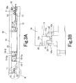
- Figs. 1 to 4 are diagrams showing the arrangement of a rotary table system according to the present invention, in which: Fig. 1 is a plan view of the rotary table system; Fig. 2 is a plan view of the rotary table system with a top table removed therefrom; Fig. 3A is a sectional view of the rotary table system (as seen from the direction of the arrow X-O-X' in Fig. 2 ); Fig. 3B is an enlarged view of part A in Fig. 3A ; and Fig. 4 is a fragmentary side view showing one half of the rotary table system.
- the rotary table system 10 has a ring-shaped (annular) integrated rail 11 with a substantially L-shaped cross-sectional configuration that has no discontinuity in the travel direction thereof.
- the rotary table system 10 further has guide blocks 12 assembled to the integrated rail 11.
- the guide blocks 12 are secured to the respective mounting surfaces of a plurality (6 in the figures) of mounting sections 17 equally spaced along the same circumference on the top of a base 13.
- the guide blocks 12 are assembled to the rail 11 from the direction of their horizontal surfaces opposing the rail 11, as will be detailed later.
- the underside of a top table (rotary table) 14 is secured to the surface (top) of the rail 11 opposite to the surface thereof opposing the guide blocks 12.
- a DD motor (direct-drive motor) 15 for applying torque to the top table 14 is disposed between the underside of the top table 14 and the top of the base 13.
- the DD motor 15 comprises a stator 15-1 having a stator core 15-1a and a rotor 15-2 having a magnet 15-2a provided along the outer periphery thereof.
- the rotor 15-2 is rotated, causing the top table 14 connected to the rotor 15-2 to rotate.
- a detecting mechanism 16 is installed at a predetermined position on the base 13 so that its detecting section (linear encoder) 16a faces the outer peripheral surface of the rail 11.
- a tape scale 20 to be detected by the linear encoder is attached to the outer peripheral surface of the rail 11 (see Fig. 5 ).
- reference numeral 18 denotes a motor cable for supplying driving electric power to the DD motor
- reference numeral 19 denotes a magnetic pole sensor cable.
- the motor cable 18 and the magnetic pole sensor cable 19 are routed through the gap between a pair of guide blocks 12 on the top of the base 13 and therefore will not interfere with the rotational motion of the top table 14 or the movement of the rail 11.
- the rotary table system disclosed in Patent Document 2 is arranged so that the guide blocks move along the endless track rail, and hence needs to machine the base to route the motor cable and so forth so that the motor cable, etc. will not interfere with the movement of the guide blocks.
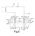
- Fig. 5 is a diagram showing the arrangement of a part of the rotary table system in which a guide block 12 is attached to the rail 11.
- Fig. 6 is a diagram showing the guide block 12 as seen from the underside thereof.
- the rail 11 has an L-shaped radial section. That is, the L-shaped rail 11 has at the distal end thereof a vertical portion 11a that is inserted into the opening of the guide block 12.
- a horizontal portion 11b extends from the upper end of the vertical portion 11a in the radial direction of the top table 14.
- a tape scale 20 to be detected by the above-described linear encoder is secured to the outer peripheral surface of the horizontal portion 11b of the rail 11.
- Ridges 21 and 22 are formed in bilateral symmetry on the left and right sides, respectively, of the part of the vertical portion 11a of the rail 11 that is inserted into the opening of the guide block 12.
- Rolling element rolling surfaces (rolling element rolling grooves in this embodiment) 21-1 and 21-2 are formed on the upper and lower corners of the ridge 21, and rolling element rolling surfaces (rolling element rolling grooves in this embodiment) 22-1 and 22-2 are formed on the upper and lower corners of the ridge 22.
- the rolling element rolling surfaces 21-1 and 21-2 and the rolling element rolling surfaces 22-1 and 22-2 are a plurality of rolling element rolling surfaces provided at bilaterally symmetric positions in the cross-section of the rail 11.
- the guide block 12 includes a block body 31 having a U-shaped cross-sectional configuration as a main body thereof.
- the block body 31 has skirt portions 32 and 33 formed on the left and right sides thereof.
- the skirt portions 32 and 33 face each other across the opening of the U-shaped block body 31.
- the width L1 of the opening of the block body 31 i.e. the spacing between the mutually opposing inner surfaces of the skirt portions 32 and 33
- the width L2 between the respective distal ends of the ridges 21 and 22 of the rail 11 (L1>L2). That is, the distal end of the vertical portion 11a of the rail 11 can be fitted into the block body 31 of the guide block 12 from above the opening thereof (i.e. the surface of the block body 31 that opposes the rail 11).
- the inner surface of the skirt portion 32 of the guide block 12 is provided with load rolling element rolling surfaces (rolling grooves in this embodiment) 32-1 and 32-2 extending in the rail travel direction so as to face the rolling element rolling surfaces 21-1 and 21-2 of the rail 11.
- the inner surface of the skirt portion 33 is provided with load rolling element rolling surfaces (rolling grooves in this embodiment) 33-1 and 33-2 extending in the rail travel direction so as to face the rolling element rolling surfaces 22-1 and 22-2 of the rail 11.
- the load rolling element rolling surfaces 32-1 and 32-2 and the load rolling element rolling surfaces 33-1 and 33-2 are a plurality of load rolling element rolling surfaces provided at bilaterally symmetric positions in a section of the guide block 12 that is perpendicular to the rail travel direction.
- skirt portion 32 is provided with rolling element relief bores 32-3 and 32-4 respectively associated with the load rolling element rolling surfaces 32-1 and 32-2.
- the skirt portion 33 is provided with rolling element relief bores 33-3 and 33-4 respectively associated with the load rolling element rolling surfaces 33-1 and 33-2.
- the rolling element rolling surfaces 21-1 and 21-2 of the rail 11 and the load rolling element rolling surfaces 32-1 and 32-2 of the guide block body 31 form load rolling element rolling passages R1 and R2, respectively.
- the rolling element rolling surfaces 22-1 and 22-2 of the rail 11 and the load rolling element rolling surfaces 33-1 and 33-2 of the guide block body 31 form load rolling element rolling passages R3 and R4, respectively.
- End plates 34 and 35 are provided at both ends of the guide block body 31 in the travel direction (axial direction) of the rail 11.
- the end plates 34 and 35 are each provided with direction change passages R5 and R6 for moving rolling elements (balls B) in the load rolling element rolling passages R1 and R2 into the rolling element relief bores 33-3 and 33-4 or moving them in the opposite direction, and further provided with direction change passages R7 and R8 for moving rolling elements (balls B) in the load rolling element rolling passages R3 and R4 into the rolling element relief bores 32-3 and 32-4 or moving them in the opposite direction.
- a multiplicity of rolling elements (balls B) roll and recirculate through rolling element recirculation passages (there are four rolling element recirculation passages in the illustrated example) respectively formed from the load rolling element rolling passages R1, R2, R3 and R4, the rolling element relief bores 32-3, 32-4, 33-3 and 33-4 and the direction change passages R5, R6, R7 and R8.
- balls B are used as the rolling elements in the above-described example, it should be noted that rollers may be used as the rolling elements.
- the width L1 of the opening of the guide block body 31 is larger than the width L2 between the distal ends of the ridges 21 and 22 of the rail 11 (L1>L2), and hence the endless integrated ring-shaped rail 11 can be fitted into the guide block body 31 from above the opening thereof.
- the end plates 34 and 35 are each made splittable into a pair of split parts so as to be capable of being assembled to the rail 11 from both sides thereof.
- Figs. 7A, 7B and 7C show a structural example of the end plate 34.
- Fig. 7A is an exploded plan view.
- Fig. 7B is an exploded front view.
- Fig. 7C is a side view.
- the end plate 34 has a substantially U-shaped configuration in a front view.
- the end plate 34 is formed from a pair of split parts 34-1 and 34-2 that are splittable to left and right in the width direction at the opening of the end plate 34.
- One split part 34-1 of the end plate 34 has a positioning pin 36 projecting from a parting surface a thereof.
- a positioning hole 37 fittable with the positioning pin 36 is provided in a parting surface b of the other split part 34-2.
- securing screw holes 38-1 and 38-2 are provided in the split parts 34-1 and 34-2, respectively.
- the two split parts 34-1 and 34-2 are brought toward each other from both sides of the rail 11 so that the parting surfaces a and b approach each other.
- the positioning pin 36 is fitted into the positioning hole 37, and the parting surfaces a and b are brought into coincidence with each other, thereby forming an end plate assembly.
- the end plate assembly is secured to one end of the block body 31 by using securing pins passed through the securing screw holes 38-1 and 38-2 of the split parts 34-1 and 34-2.
- reference numeral 39 denotes an oil hole.
- the split parts 34-1 and 34-2 which constitute the end plate 34, are brought toward each other from both sides of the rail 11. Then, the positioning pin 36 is fitted into the positioning hole 37, and the parting surfaces a and b are brought into coincidence with each other to form an end plate assembly. Accordingly, the split parts 34-1 and 34-2 can be positioned with respect to each other with high accuracy. Further, the end plate assembly is secured to one end of the guide block body 31 by using securing screws passed through the securing screw holes 38-1 and 38-2. Thus, the split parts 34-1 and 34-2 can be positioned and secured with high accuracy, and no displacement will occur during use.
- the end plate 35 is also arranged in the same way as the end plate 34, so that it can be secured to another end of the block body 31 by bringing a pair of split parts toward each other from both sides of the rail 11.
- the arrangement of the end plates 34 and 35 is not necessarily limited to the above.
- each end plate may be arranged so that it can be assembled by bringing a pair of split parts toward each other from both sides of the rail 11.
- Each end plate may be formed from a material having elasticity so that it can be fitted onto the rail 11 from the lower side thereof by expanding the width of the opening of the end plate using the elasticity.
- the rail 11 moves together with the top table 14, being guided by a plurality (6 in this embodiment) of guide blocks 12.
- the movement of the rail 11 is detected by the detecting section 16a of the detecting mechanism 16.
- a tape scale 20 is attached to the outer peripheral surface of the horizontal portion 11b, which is the largest outer diameter portion of the L-shaped rail 11, and the scale 20 is detected by a linear encoder, which constitutes the detecting section 16a, as has been stated above.
- the amount of rotation of the top table 14 can be detected with a higher resolution than by a method in which the rotational position of the rotor 15-2 of the DD motor 15, shown in Fig. 3C , is detected with a magnetic sensor, for example. Accordingly, it becomes possible to finely control the rotation of the top table 14.
- flanges 12a on both sides of the guide block 12 are provided with holes for passing screws 23, and the guide block 12 is secured to the mounting surface with the screws 13 passed through the holes.
- the guide blocks 12 are secured to the accurately machined mounting surfaces of the mounting sections 17. Therefore, it is possible to realize a high-precision rotary table system.
- the rail 11 is guided by a plurality of guide blocks 12 arranged as stated above, even if a preload is applied to the rolling elements interposed between the rolling element rolling surfaces of the rail 11 and the rolling element rolling surfaces of the guide block body 31 to prevent backlash, it is possible to realize a rotary table system capable of rotating the top table 14 with lower torque than in an arrangement wherein a large number of rolling elements are disposed on the entire circumference of the rail 11, and the rolling elements are preloaded, for example.
- the rolling element rolling surfaces 21-1 and 21-2 and the rolling element rolling surfaces 22-1 and 22-2 formed on the rail 11 are a plurality of rolling element rolling surfaces provided at bilaterally symmetric positions in the cross-section of the rail 11, and the load rolling element rolling surfaces 32-1 and 32-2 and the load rolling element rolling surfaces 33-1 and 33-2 formed on the guide block 12 are a plurality of load rolling element rolling surfaces provided at bilaterally symmetric positions in a section of the guide block 12 that is perpendicular to the rail travel direction.
- the left and right (inner and outer peripheral) sides of the rail can be supported with good balance in comparison to an arrangement in which rolling element rolling surfaces and load rolling element rolling surfaces are provided in bilateral asymmetry on the rail and the guide block, as in the rotary table system disclosed in Patent Document 2, for example. Accordingly, it is possible to minimize radial and axial vibrations of the top table 14.
- the integrated rail 11 has the vertical portion 11a and the horizontal portion 11b in a substantially L-shaped cross-sectional configuration, as has been stated above. Therefore, when the underside of the top table 14 and the top of the rail 11 are to be joined to each other, screw holes are provided in the horizontal portion 11b from the underside thereof so as to extend into the top table 14, and screws 25 are threaded into the screw holes, whereby the rail 11 can be joined to the top table 14. Accordingly, the vertical portion 11a of the rail 11, which slides along the guide blocks 12, need not be subjected to machining for mounting the top table 14. Thus, the surface of the rail 11 that slides along the guide blocks 12 remains being a smooth surface having the same high accuracy as that obtained upon completion of the rail machining process.
- each guide block 12 contact the sliding surface of the rail 11 with a constant frictional force at all times, so that there will be no torque fluctuation or the like.
- a high-precision rotary table system can be realized.
- the rail 11 is formed into a substantially L-shaped cross-sectional configuration, the moment of inertia of area of the rail 11 increases. Accordingly, even if the rail 11 is ground with high accuracy and thereafter subjected to treatment such as quenching, the high accuracy can be maintained. There will be a minimal change in coaxiality of the rail 11, and rail aging distortion or the like will be very small. In this respect also, it is possible to realize a high-precision rotary table system having minimal axial and radial run-outs.
- the whole circumference of the top table 14 is supported by the horizontal portion 11b of the integrated rail 11, and the movement of the rail 11 is guided by a plurality of guide blocks 12 equally spaced along the same circumference on the top of the base 13.
- the rail 11 has no joint, and hence there is no rattling due to joints.
- axial and radial run-outs are reduced, and the accuracy increases to a considerable extent.
- the rail 11 is arranged in a substantially L-shaped cross-sectional configuration formed from a vertical portion and a horizontal portion
- the rail is not necessarily limited to the above-described configuration but may be formed in a substantially rectangular cross-sectional configuration.
- the surface of the rail 11 that slides along the guide blocks 12 is subjected to machining for mounting the top table. Therefore, there will be torque fluctuations when the seal members, etc. provided at both ends of each guide block 12 pass the machined portions of the rail 11, and the accuracy will be reduced correspondingly to the torque fluctuations.
- the rotary table system arranged as stated above is superior to conventional rotary table systems, e.g. cross roller guide type, angular contact bearing type and tapered roller type rotary table systems, from all the viewpoints of achieving high axial and radial run-out accuracy, high resolution, thickness reduction, and upsizing.
- conventional rotary table systems e.g. cross roller guide type, angular contact bearing type and tapered roller type rotary table systems
- the rotary table system can move an iron column (100 kg) of ⁇ 650 ⁇ 38 in the following patterns:
- the present invention provides a guide apparatus including a ring-shaped integrated rail having no discontinuity in the travel direction thereof.
- the guide apparatus further includes a plurality of guide blocks that are assembled to the rail from the direction of their surfaces opposing the rail.
- the surface of the rail opposite to the surface thereof opposing the guide blocks is joined to the underside of a rotary table, thereby allowing the rail to rotate together with the rotary table.
- the rail has no joint and has a high degree of coaxiality in comparison, for example, to a split rail that is formed from split members. Therefore, the rotary table system is excellent in axial and radial run-out accuracy.
- the rail is joined to the rotary table, the whole circumference of the rotary table is supported by the rail having a substantially L-shaped cross-sectional configuration, unlike the arrangement in which the rotary table is supported by a plurality of guide blocks, as disclosed in Patent Document 2. Accordingly, the rigidity of the rotary table increases, and in this respect also, the accuracy increases.
- the rail has a substantially L-shaped cross-sectional configuration formed from a vertical portion and a horizontal portion extending from the upper end of the vertical portion in the radial direction of the rotary table.
- the horizontal portion of the rail can be joined to the rotary table, and the surface of the vertical portion of the rail that slides along the guide blocks need not be machined to form mounting holes for mounting bolts, for example.
- the rail surface that slides along the guide blocks is kept smooth (i.e. the rail surface remains as smooth as it was when the endless track rail was produced with high accuracy). Consequently, there is no torque fluctuation which would otherwise occur when the seal members, etc. provided at both ends of each guide block pass the machined mounting portions of the rail.
- a high-precision rotary table system can be realized.
- the rail is formed into a substantially L-shaped cross-sectional configuration, the moment of inertia of area and cross-sectional area of the rail increase. Accordingly, even if the rail is ground with high accuracy and thereafter subjected to treatment such as quenching, the high accuracy can be maintained. Rail aging distortion is also small. Thus, it is possible to realize a high-precision rotary table system having minimal axial and radial run-outs.
- the rotation (rotational position) of the rotary table can be detected with a high resolution, and it is possible to realize a rotary table system capable of fine rotation control.
- the mounting sections are equally spaced along the same circumference on a base that is a separate member from the rail and the guide blocks, the accuracy increases owing to the equalizing effect, and an extra-thin rotary table system can be realized.
- the guide blocks each include a guide block body having load rolling element rolling surfaces that form load rolling element rolling passages in cooperation with a plurality of rolling element rolling surfaces formed on the rail.
- the guide block body further has rolling element relief bores associated with the load rolling element rolling surfaces.
- Each guide block further includes end plates provided at both ends of the guide block body in the travel direction of the rail.
- Each end plate has rolling element direction change passages that form rolling element recirculation passages in cooperation with the load rolling element rolling passages and the rolling element relief bores. Accordingly, it is possible to provide a rotary table system having minimal axial and radial run-outs and capable of rotating with extremely low torque by making use of the characteristics of the guide blocks.
Landscapes
- Engineering & Computer Science (AREA)
- General Engineering & Computer Science (AREA)
- Mechanical Engineering (AREA)
- Machine Tool Units (AREA)
- Bearings For Parts Moving Linearly (AREA)
- Details Of Measuring And Other Instruments (AREA)
Claims (5)
- Système de plateau tournant (10) comprenant :une base (13) ;un appareil de guidage ; etun plateau tournant (14) monté sur ledit appareil de guidage, ledit plateau tournant (14) pouvant tourner par rapport à ladite base (13) au moyen dudit appareil de guidage ;ledit appareil de guidage comportant un rail annulaire intégré (11), et une pluralité de blocs de guidage (12) qui sont assemblés audit rail (11) à partir d'une direction de leurs surfaces opposées audit rail (11) ; oùledit rail annulaire intégré (11) n'a pas de joint afin de n'avoir aucune discontinuité dans une direction de déplacement de celui-ci, caractérisé en ce quelesdits blocs de guidage (12) sont fixés à ladite base (13), etune surface entière dudit rail (11) opposée à une surface de celui-ci qui est opposée auxdits blocs de guidage (12) et une face inférieure dudit plateau tournant (14) sont reliées ensemble.
- Système de plateau tournant selon la revendication 1, dans lequel ledit rail (11) a une configuration de coupe transversale essentiellement en forme de L formée d'une partie verticale et d'une partie horizontale s'étendant depuis une extrémité supérieure de ladite partie verticale dans une direction radiale dudit plateau tournant (14).
- Système de plateau tournant selon la revendication 1 ou 2, comprenant en outre :un mécanisme de détection (16) qui détecte une quantité de rotation dudit plateau tournant (14) ;dans lequel une échelle à bande (20) qui doit être détectée par ledit mécanisme de détection (16) est prévue sur une surface périphérique externe dudit rail (11).
- Système de plateau tournant selon l'une quelconque des revendications 1 à 3, comprenant en outre :des sections de montage (17) ayant des surfaces de montage auxquelles lesdits blocs de guidage (12) sont fixés, lesdites sections de montage (17) étant équidistantes le long d'une même circonférence sur une base (13) qui est un élément séparé dudit rail (11) et des blocs de guidage (12).
- Système de plateau tournant selon l'une quelconque des revendications 1 à 4, dans lequel ledit rail (11) a une pluralité de surfaces de roulement d'élément de roulement (21-1, 21-2, 22-1, 22-2) formées le long de la direction de déplacement dudit rail (11) ;
lesdits blocs de guidage (12) comportant chacun :un corps de bloc de guidage (31) ayant des surfaces de roulement d'élément de roulement de charge (32-1, 32-2, 33-1, 33-2) qui forment des passages de roulement d'élément de roulement de charge (R1, R2, R3, R4) en coopération avec lesdites surfaces de roulement d'élément de roulement (21-1, 21-2, 22-1, 22-2), ledit corps de bloc de guidage (31) ayant en outre des alésages de décharge d'élément de roulement (32-3, 32-4, 33-3, 33-4) associés auxdites surfaces de roulement d'élément d'enroulement de charge (32-1, 32-2, 33-1, 33-2) ; etdes plaques d'extrémité (34, 35) prévues au niveau des deux extrémités dudit corps de bloc de guidage (31) dans la direction de déplacement dudit rail (11), lesdites plaques d'extrémité (34, 35) ayant chacune des passages de changement de direction d'élément de roulement (R5, R6, R7, R8) qui forment des passages de recirculation d'élément de roulement en coopération avec lesdits passages de roulement d'élément de roulement de charge (R1, R2, R3, R4) et des alésages de décharge d'élément de roulement (32-3, 32-4, 33-3, 33-4).
Applications Claiming Priority (2)
| Application Number | Priority Date | Filing Date | Title |
|---|---|---|---|
| JP2004015165A JP4575674B2 (ja) | 2004-01-23 | 2004-01-23 | 回転テーブル装置 |
| PCT/JP2005/000702 WO2005071690A1 (fr) | 2004-01-23 | 2005-01-20 | Dispositif a table rotative |
Publications (3)
| Publication Number | Publication Date |
|---|---|
| EP1708206A1 EP1708206A1 (fr) | 2006-10-04 |
| EP1708206A4 EP1708206A4 (fr) | 2010-08-04 |
| EP1708206B1 true EP1708206B1 (fr) | 2014-09-24 |
Family
ID=34805447
Family Applications (1)
| Application Number | Title | Priority Date | Filing Date |
|---|---|---|---|
| EP05703930.7A Expired - Lifetime EP1708206B1 (fr) | 2004-01-23 | 2005-01-20 | Dispositif a table rotative |
Country Status (8)
| Country | Link |
|---|---|
| US (1) | US7798071B2 (fr) |
| EP (1) | EP1708206B1 (fr) |
| JP (1) | JP4575674B2 (fr) |
| KR (1) | KR101240790B1 (fr) |
| CN (1) | CN1910702B (fr) |
| ES (1) | ES2524582T3 (fr) |
| TW (1) | TW200535366A (fr) |
| WO (1) | WO2005071690A1 (fr) |
Families Citing this family (23)
| Publication number | Priority date | Publication date | Assignee | Title |
|---|---|---|---|---|
| ES2293432T3 (es) | 2004-07-07 | 2008-03-16 | Black & Decker Inc. | Soporte para herramientas de mesa. |
| KR101238991B1 (ko) * | 2005-03-18 | 2013-03-04 | 티에치케이 가부시끼가이샤 | 안내 장치 |
| GB0505798D0 (en) * | 2005-03-22 | 2005-04-27 | Wardle Frank P | Squeeze film damper for aerostatic slides and rotary tables |
| CN101809300B (zh) * | 2007-09-28 | 2013-03-20 | Thk株式会社 | 旋转环 |
| JP4812802B2 (ja) * | 2008-05-14 | 2011-11-09 | 国際計測器株式会社 | 振動試験装置、直動アクチュエータ及び直動変換器 |
| US20090320724A1 (en) * | 2008-06-27 | 2009-12-31 | Walburn William L | Swivel base with installation aid |
| WO2010013341A1 (fr) * | 2008-07-31 | 2010-02-04 | Thk株式会社 | Structure de basculement |
| JP2010090920A (ja) * | 2008-10-03 | 2010-04-22 | Nsk Ltd | 曲線運動案内装置 |
| DE102009031624B4 (de) | 2009-07-03 | 2011-04-07 | Aktiebolaget Skf | Lageranordnung |
| US8413972B2 (en) | 2009-10-08 | 2013-04-09 | Lincoln Global, Inc. | Multiple axis positioner |
| CN101799042B (zh) * | 2010-03-12 | 2012-04-18 | 洛阳世必爱特种轴承有限公司 | 一种回转台的角位移测控轴承单元 |
| TWI412424B (zh) * | 2010-12-03 | 2013-10-21 | Ind Tech Res Inst | 支撐軸承 |
| US8607665B1 (en) * | 2011-08-13 | 2013-12-17 | Kun-Jung Hung | Rotary table device which can be tuned flexibly to operate individually |
| CN103543295A (zh) * | 2012-07-17 | 2014-01-29 | 鸿富锦精密工业(深圳)有限公司 | 测试转台 |
| CN103576015B (zh) * | 2012-07-31 | 2016-09-21 | 冯金泉 | 转台 |
| US9459121B2 (en) | 2013-05-21 | 2016-10-04 | DigiPas USA, LLC | Angle measuring device and methods for calibration |
| CN106125770B (zh) * | 2016-07-22 | 2019-06-07 | 西安电子科技大学 | 一种方位-俯仰运动两轴座架 |
| CN106486172B (zh) * | 2016-10-13 | 2019-04-30 | 河南壹通智能科技有限公司 | 一种三维扫描系统的旋转工作台 |
| KR101958460B1 (ko) * | 2017-10-12 | 2019-07-04 | 윤인철 | 이동식 선박 러그 밀링장치 |
| CN110449922B (zh) * | 2019-07-09 | 2021-03-12 | 科德数控股份有限公司 | 一种嵌套式数控转台 |
| JP7322095B2 (ja) * | 2021-05-27 | 2023-08-07 | 日本トムソン株式会社 | 回転テーブル |
| US12594487B2 (en) * | 2021-09-26 | 2026-04-07 | Shenzhen Shi Hu Lian Heng Tong Trading Co. Ltd. | Jigsaw puzzle table |
| US20250058210A1 (en) * | 2021-09-26 | 2025-02-20 | Shenzhen Shi Hu Lian Heng Tong Trading Co. Ltd. | Jigsaw Puzzle Table |
Family Cites Families (23)
| Publication number | Priority date | Publication date | Assignee | Title |
|---|---|---|---|---|
| US4886948A (en) * | 1978-04-17 | 1989-12-12 | Plastics, Inc. | Portable turntable with shielded drive motor for microwave ovens |
| US4555990A (en) * | 1984-05-29 | 1985-12-03 | Genroku Corporation | Rotary board |
| US4694132A (en) * | 1986-10-22 | 1987-09-15 | Liu Yiu C | Microwave oven turntable with removable table top |
| JPH0251617A (ja) * | 1988-08-16 | 1990-02-21 | T Echi K Kk | 直線摺動用ベアリング及び直線摺動用テーブル |
| US5163651A (en) * | 1990-03-13 | 1992-11-17 | Ntn Corporation | Movable table |
| JP3242487B2 (ja) | 1993-04-23 | 2001-12-25 | 日本トムソン株式会社 | 転がり案内ユニット |
| US5575565A (en) * | 1993-11-08 | 1996-11-19 | Nippon Thompson Co., Ltd. | Rolling guide unit |
| JPH0729325U (ja) * | 1993-11-08 | 1995-06-02 | 日本トムソン株式会社 | 転がり案内ユニット |
| JPH0849756A (ja) * | 1994-06-24 | 1996-02-20 | Sozoan:Kk | 回転運動機構 |
| JPH0821440A (ja) * | 1994-07-05 | 1996-01-23 | Thk Kk | 曲線運動案内装置およびそれを用いた回転テ−ブル装置 |
| JP3254082B2 (ja) | 1994-07-05 | 2002-02-04 | テイエチケー株式会社 | 曲線運動案内装置 |
| US5533844A (en) * | 1994-11-15 | 1996-07-09 | Ekleberry; Donald A. | Travelling platen with extended axis |
| JPH0979253A (ja) | 1995-09-20 | 1997-03-25 | Meidensha Corp | 回転テーブル |
| JPH09125736A (ja) | 1995-10-27 | 1997-05-13 | Thk Kk | 回転テーブル装置 |
| US5809834A (en) * | 1996-06-14 | 1998-09-22 | Mrba Company | Motion roller bearing assembly |
| US5784932A (en) * | 1996-06-20 | 1998-07-28 | Gilberti; Joseph J. | Rotary indexing table |
| JPH1130233A (ja) * | 1997-07-09 | 1999-02-02 | Thk Kk | 直線運動案内装置 |
| JPH11300557A (ja) * | 1998-04-15 | 1999-11-02 | Thk Co Ltd | 移動テーブル装置 |
| JP3651287B2 (ja) * | 1998-11-27 | 2005-05-25 | 株式会社村田製作所 | 加工装置 |
| JP2001241437A (ja) | 2000-02-29 | 2001-09-07 | Nippon Thompson Co Ltd | 曲動転がり案内ユニット |
| US6868794B2 (en) * | 2002-10-08 | 2005-03-22 | Newport News Shipbuilding And Dry Dock Company | Material turn table |
| JP2004160642A (ja) * | 2002-10-22 | 2004-06-10 | Sankyo Mfg Co Ltd | 傾斜回動テーブル装置 |
| US6997512B1 (en) * | 2004-12-23 | 2006-02-14 | Ming-Ming Yu | 360 degree swivel cushion for bathroom use |
-
2004
- 2004-01-23 JP JP2004015165A patent/JP4575674B2/ja not_active Expired - Lifetime
-
2005
- 2005-01-20 ES ES05703930.7T patent/ES2524582T3/es not_active Expired - Lifetime
- 2005-01-20 KR KR1020067012312A patent/KR101240790B1/ko not_active Expired - Lifetime
- 2005-01-20 WO PCT/JP2005/000702 patent/WO2005071690A1/fr not_active Ceased
- 2005-01-20 EP EP05703930.7A patent/EP1708206B1/fr not_active Expired - Lifetime
- 2005-01-20 CN CN2005800029920A patent/CN1910702B/zh not_active Expired - Lifetime
- 2005-01-20 US US10/586,482 patent/US7798071B2/en active Active
- 2005-01-21 TW TW094101873A patent/TW200535366A/zh not_active IP Right Cessation
Also Published As
| Publication number | Publication date |
|---|---|
| WO2005071690A1 (fr) | 2005-08-04 |
| CN1910702A (zh) | 2007-02-07 |
| TW200535366A (en) | 2005-11-01 |
| ES2524582T3 (es) | 2014-12-10 |
| KR20060127866A (ko) | 2006-12-13 |
| TWI356139B (fr) | 2012-01-11 |
| EP1708206A4 (fr) | 2010-08-04 |
| KR101240790B1 (ko) | 2013-03-08 |
| CN1910702B (zh) | 2010-05-05 |
| JP2005205549A (ja) | 2005-08-04 |
| JP4575674B2 (ja) | 2010-11-04 |
| US7798071B2 (en) | 2010-09-21 |
| EP1708206A1 (fr) | 2006-10-04 |
| US20070116392A1 (en) | 2007-05-24 |
Similar Documents
| Publication | Publication Date | Title |
|---|---|---|
| US7798071B2 (en) | Rotary table system | |
| EP1257045A2 (fr) | Table XY avec moteur linéaire intégré | |
| JP4560235B2 (ja) | 角度調整テーブル装置 | |
| US7223018B2 (en) | Biaxial linear-revolving position control and table system using the same | |
| EP0752072A1 (fr) | Palier a mouvement lineaire | |
| CN113805617A (zh) | 一种可调恒力机构 | |
| JPS63123644A (ja) | 循環型ローラーベアリング装置および作成方法 | |
| US6547437B2 (en) | Curvilinear motion guide units | |
| US6210039B1 (en) | Linear motion guide unit and table guide apparatus utilizing the same | |
| CN120756808A (zh) | 一种精密输送的链节式环形导轨 | |
| JP4074170B2 (ja) | リニアモータを用いた送り装置 | |
| JP2012082879A (ja) | 運動案内装置 | |
| JPS61247264A (ja) | リニアモ−タ | |
| JPH0713941Y2 (ja) | テーブル送り装置 | |
| JP4613543B2 (ja) | スライドコアガイド装置及びこれを具備した射出成形金型機構 | |
| JP2001221229A (ja) | 直線運動軸受 | |
| JPH07130109A (ja) | 往復移動体の支持機構 | |
| CN120839670A (zh) | 一种旋转机构和磨床 | |
| JPH03288378A (ja) | 磁気ディスク装置のリニアアクチュエータ用案内機構 | |
| JPH05280538A (ja) | 転がり案内ユニット | |
| JPS59214526A (ja) | 移動テ−ブル | |
| JPH04322929A (ja) | 水平自由移動案内機構 | |
| JPH10159933A (ja) | 磁気ねじ装置 | |
| JPS6176247A (ja) | 直線案内装置 | |
| JPH0318424B2 (fr) |
Legal Events
| Date | Code | Title | Description |
|---|---|---|---|
| PUAI | Public reference made under article 153(3) epc to a published international application that has entered the european phase |
Free format text: ORIGINAL CODE: 0009012 |
|
| 17P | Request for examination filed |
Effective date: 20060621 |
|
| AK | Designated contracting states |
Kind code of ref document: A1 Designated state(s): DE ES FR IT |
|
| DAX | Request for extension of the european patent (deleted) | ||
| RBV | Designated contracting states (corrected) |
Designated state(s): DE ES FR IT |
|
| A4 | Supplementary search report drawn up and despatched |
Effective date: 20100701 |
|
| 17Q | First examination report despatched |
Effective date: 20110217 |
|
| GRAP | Despatch of communication of intention to grant a patent |
Free format text: ORIGINAL CODE: EPIDOSNIGR1 |
|
| INTG | Intention to grant announced |
Effective date: 20140416 |
|
| GRAS | Grant fee paid |
Free format text: ORIGINAL CODE: EPIDOSNIGR3 |
|
| GRAA | (expected) grant |
Free format text: ORIGINAL CODE: 0009210 |
|
| AK | Designated contracting states |
Kind code of ref document: B1 Designated state(s): DE ES FR IT |
|
| REG | Reference to a national code |
Ref country code: DE Ref legal event code: R096 Ref document number: 602005044777 Country of ref document: DE Effective date: 20141106 |
|
| REG | Reference to a national code |
Ref country code: ES Ref legal event code: FG2A Ref document number: 2524582 Country of ref document: ES Kind code of ref document: T3 Effective date: 20141210 |
|
| REG | Reference to a national code |
Ref country code: DE Ref legal event code: R097 Ref document number: 602005044777 Country of ref document: DE |
|
| PLBE | No opposition filed within time limit |
Free format text: ORIGINAL CODE: 0009261 |
|
| STAA | Information on the status of an ep patent application or granted ep patent |
Free format text: STATUS: NO OPPOSITION FILED WITHIN TIME LIMIT |
|
| 26N | No opposition filed |
Effective date: 20150625 |
|
| REG | Reference to a national code |
Ref country code: FR Ref legal event code: PLFP Year of fee payment: 12 |
|
| REG | Reference to a national code |
Ref country code: FR Ref legal event code: PLFP Year of fee payment: 13 |
|
| REG | Reference to a national code |
Ref country code: FR Ref legal event code: PLFP Year of fee payment: 14 |
|
| PGFP | Annual fee paid to national office [announced via postgrant information from national office to epo] |
Ref country code: ES Payment date: 20240223 Year of fee payment: 20 |
|
| PGFP | Annual fee paid to national office [announced via postgrant information from national office to epo] |
Ref country code: DE Payment date: 20240119 Year of fee payment: 20 |
|
| PGFP | Annual fee paid to national office [announced via postgrant information from national office to epo] |
Ref country code: IT Payment date: 20240129 Year of fee payment: 20 Ref country code: FR Payment date: 20240124 Year of fee payment: 20 |
|
| REG | Reference to a national code |
Ref country code: DE Ref legal event code: R071 Ref document number: 602005044777 Country of ref document: DE |
|
| REG | Reference to a national code |
Ref country code: ES Ref legal event code: FD2A Effective date: 20250130 |
|
| PG25 | Lapsed in a contracting state [announced via postgrant information from national office to epo] |
Ref country code: ES Free format text: LAPSE BECAUSE OF EXPIRATION OF PROTECTION Effective date: 20250121 |