EP3260868A1 - Verfahren zur bestimmung einer übergabeposition und laborautomatisierungssystem - Google Patents
Verfahren zur bestimmung einer übergabeposition und laborautomatisierungssystem Download PDFInfo
- Publication number
- EP3260868A1 EP3260868A1 EP17177008.4A EP17177008A EP3260868A1 EP 3260868 A1 EP3260868 A1 EP 3260868A1 EP 17177008 A EP17177008 A EP 17177008A EP 3260868 A1 EP3260868 A1 EP 3260868A1
- Authority
- EP
- European Patent Office
- Prior art keywords
- transport plane
- sample container
- handover
- electro
- magnetic
- Prior art date
- Legal status (The legal status is an assumption and is not a legal conclusion. Google has not performed a legal analysis and makes no representation as to the accuracy of the status listed.)
- Granted
Links
Images

Classifications
-
- G—PHYSICS
- G01—MEASURING; TESTING
- G01N—INVESTIGATING OR ANALYSING MATERIALS BY DETERMINING THEIR CHEMICAL OR PHYSICAL PROPERTIES
- G01N33/00—Investigating or analysing materials by specific methods not covered by groups G01N1/00 - G01N31/00
- G01N33/48—Biological material, e.g. blood, urine; Haemocytometers
- G01N33/483—Physical analysis of biological material
- G01N33/487—Physical analysis of biological material of liquid biological material
- G01N33/4875—Details of handling test elements, e.g. dispensing or storage, not specific to a particular test method
-
- B—PERFORMING OPERATIONS; TRANSPORTING
- B65—CONVEYING; PACKING; STORING; HANDLING THIN OR FILAMENTARY MATERIAL
- B65G—TRANSPORT OR STORAGE DEVICES, e.g. CONVEYORS FOR LOADING OR TIPPING, SHOP CONVEYOR SYSTEMS OR PNEUMATIC TUBE CONVEYORS
- B65G54/00—Non-mechanical conveyors not otherwise provided for
- B65G54/02—Non-mechanical conveyors not otherwise provided for electrostatic, electric, or magnetic
-
- F—MECHANICAL ENGINEERING; LIGHTING; HEATING; WEAPONS; BLASTING
- F16—ENGINEERING ELEMENTS AND UNITS; GENERAL MEASURES FOR PRODUCING AND MAINTAINING EFFECTIVE FUNCTIONING OF MACHINES OR INSTALLATIONS; THERMAL INSULATION IN GENERAL
- F16K—VALVES; TAPS; COCKS; ACTUATING-FLOATS; DEVICES FOR VENTING OR AERATING
- F16K31/00—Actuating devices; Operating means; Releasing devices
- F16K31/004—Actuating devices; Operating means; Releasing devices actuated by piezoelectric means
-
- G—PHYSICS
- G01—MEASURING; TESTING
- G01N—INVESTIGATING OR ANALYSING MATERIALS BY DETERMINING THEIR CHEMICAL OR PHYSICAL PROPERTIES
- G01N35/00—Automatic analysis not limited to methods or materials provided for in any single one of groups G01N1/00 - G01N33/00; Handling materials therefor
- G01N35/0099—Automatic analysis not limited to methods or materials provided for in any single one of groups G01N1/00 - G01N33/00; Handling materials therefor comprising robots or similar manipulators
-
- G—PHYSICS
- G01—MEASURING; TESTING
- G01N—INVESTIGATING OR ANALYSING MATERIALS BY DETERMINING THEIR CHEMICAL OR PHYSICAL PROPERTIES
- G01N35/00—Automatic analysis not limited to methods or materials provided for in any single one of groups G01N1/00 - G01N33/00; Handling materials therefor
- G01N35/02—Automatic analysis not limited to methods or materials provided for in any single one of groups G01N1/00 - G01N33/00; Handling materials therefor using a plurality of sample containers moved by a conveyor system past one or more treatment or analysis stations
- G01N35/04—Details of the conveyor system
-
- G—PHYSICS
- G01—MEASURING; TESTING
- G01N—INVESTIGATING OR ANALYSING MATERIALS BY DETERMINING THEIR CHEMICAL OR PHYSICAL PROPERTIES
- G01N35/00—Automatic analysis not limited to methods or materials provided for in any single one of groups G01N1/00 - G01N33/00; Handling materials therefor
- G01N35/02—Automatic analysis not limited to methods or materials provided for in any single one of groups G01N1/00 - G01N33/00; Handling materials therefor using a plurality of sample containers moved by a conveyor system past one or more treatment or analysis stations
- G01N35/04—Details of the conveyor system
- G01N2035/0401—Sample carriers, cuvettes or reaction vessels
- G01N2035/0406—Individual bottles or tubes
-
- G—PHYSICS
- G01—MEASURING; TESTING
- G01N—INVESTIGATING OR ANALYSING MATERIALS BY DETERMINING THEIR CHEMICAL OR PHYSICAL PROPERTIES
- G01N35/00—Automatic analysis not limited to methods or materials provided for in any single one of groups G01N1/00 - G01N33/00; Handling materials therefor
- G01N35/02—Automatic analysis not limited to methods or materials provided for in any single one of groups G01N1/00 - G01N33/00; Handling materials therefor using a plurality of sample containers moved by a conveyor system past one or more treatment or analysis stations
- G01N35/04—Details of the conveyor system
- G01N2035/046—General conveyor features
- G01N2035/0465—Loading or unloading the conveyor
-
- G—PHYSICS
- G01—MEASURING; TESTING
- G01N—INVESTIGATING OR ANALYSING MATERIALS BY DETERMINING THEIR CHEMICAL OR PHYSICAL PROPERTIES
- G01N35/00—Automatic analysis not limited to methods or materials provided for in any single one of groups G01N1/00 - G01N33/00; Handling materials therefor
- G01N35/02—Automatic analysis not limited to methods or materials provided for in any single one of groups G01N1/00 - G01N33/00; Handling materials therefor using a plurality of sample containers moved by a conveyor system past one or more treatment or analysis stations
- G01N35/04—Details of the conveyor system
- G01N2035/0474—Details of actuating means for conveyors or pipettes
- G01N2035/0477—Magnetic
-
- G—PHYSICS
- G01—MEASURING; TESTING
- G01N—INVESTIGATING OR ANALYSING MATERIALS BY DETERMINING THEIR CHEMICAL OR PHYSICAL PROPERTIES
- G01N35/00—Automatic analysis not limited to methods or materials provided for in any single one of groups G01N1/00 - G01N33/00; Handling materials therefor
- G01N35/02—Automatic analysis not limited to methods or materials provided for in any single one of groups G01N1/00 - G01N33/00; Handling materials therefor using a plurality of sample containers moved by a conveyor system past one or more treatment or analysis stations
- G01N35/04—Details of the conveyor system
- G01N2035/0474—Details of actuating means for conveyors or pipettes
- G01N2035/0491—Position sensing, encoding; closed-loop control
- G01N2035/0493—Locating samples; identifying different tube sizes
-
- G—PHYSICS
- G01—MEASURING; TESTING
- G01N—INVESTIGATING OR ANALYSING MATERIALS BY DETERMINING THEIR CHEMICAL OR PHYSICAL PROPERTIES
- G01N35/00—Automatic analysis not limited to methods or materials provided for in any single one of groups G01N1/00 - G01N33/00; Handling materials therefor
- G01N35/02—Automatic analysis not limited to methods or materials provided for in any single one of groups G01N1/00 - G01N33/00; Handling materials therefor using a plurality of sample containers moved by a conveyor system past one or more treatment or analysis stations
- G01N35/04—Details of the conveyor system
- G01N2035/0474—Details of actuating means for conveyors or pipettes
- G01N2035/0491—Position sensing, encoding; closed-loop control
- G01N2035/0494—Detecting or compensating piositioning errors
Definitions
- the invention relates to a method of setting a handover position of a gripping device, which may be used in conjunction with a laboratory automation system.
- the invention relates further to a laboratory automation system being configured to perform such a method.
- Gripping devices are often used in laboratory automation systems, especially in order to place sample containers into sample container carriers being movable on a transport plane, and in order to remove sample containers from such sample container carriers.
- Known laboratory sample distribution systems are typically used in laboratory automation systems in order to transport samples contained in sample containers between different laboratory stations.
- a laboratory sample distribution system is e.g. disclosed in document WO 2013/064656 A1 .
- Such a laboratory sample distribution system provides for a high throughput and for reliable operation.
- an internal coordinate system of the gripping device differs from an internal coordinate system of the laboratory sample distribution system.
- a handover position being typically a position on which a sample container carrier has to be placed in order to be handled by the gripping device, has to be taught in. This typically implies that that the different coordinate systems are aligned with one another.
- this object is achieved by a method according to claim 1 and by a laboratory automation system according to claim 12.
- the invention relates to a method of setting a handover position of a gripping device.
- the gripping device is assigned to a laboratory sample distribution system having a transport plane, a number (e.g. 64 to 64000) of electro-magnetic actuators positioned below the transport plane and a number (e.g. 64 to 64000) of position sensors distributed over the transport plane, e.g. in form of magnetic sensors (e.g. Hall sensors).
- the position sensors can be arranged in rows and columns under the transport plane. Accordingly, the electro-magnetic actuators can be arranged in rows and columns under the transport plane.
- the handover position is assigned to a handover electro-magnetic actuator, wherein the handover electro-magnetic actuator is typically one of the number of electro-magnetic actuators.
- the handover position is typically a position at which the gripping device grips a sample container being contained in or carried by a sample container carrier being movably arranged on the transport plane, or at which the gripping device hands over or inserts a sample container to/into a sample container carrier.
- the method comprises the following steps:
- the handover position is set and represented in a coordinate system of the gripping device. Typically, this corresponds to a coordinate system used by a control device of the gripping device.
- the handover position is calculated based on a difference between the first position and a center position of the handover electro-magnetic actuator. This allows for an easy calculation.
- the position sensors are configured to measure a quantitative strength of a magnetic field generated (caused) by the magnetically active device of the positioning determining device. This allows a position determination having a high resolution, especially compared with position sensors giving only binary signals.
- the position sensors are further configured to measure a quantitative strength of a magnetic field generated by a respective magnetically active device of a sample container carrier.
- the first position is determined based on the strengths of the magnetic field measured by some or all of the position sensors.
- the first position for detecting the first position (only) position sensors surrounding the handover electro-magnetic actuator are used.
- the first position is determined based on the strengths of the magnetic field measured by position sensors surrounding the handover electro-magnetic actuator as well as the sensor at the handover position itself.
- the electro-magnetic actuators are deactivated while performing the method. This avoids that the measurement is disturbed by magnetic fields generated (caused) by the electro-magnetic actuators.
- the first position and/or the center position are represented by planar (Cartesian) coordinates on the transport plane.
- planar coordinates are well suited because most transport planes have a rectangular shape.
- other types of coordinates for example circular coordinates, can be used.
- the step of positioning, by means of the gripping device, the position determining device on the transport plane is performed such that the gripping device is positioned over or besides the handover electro-magnetic actuator. This allows for a small and exactly measurable distance between the handover electro-magnetic actuator and the position determining device.
- the step of positioning the position determining device, while being held by the gripping device, on the transport plane is performed automatically.
- the automatic positioning can place the position determining device to a predefined or assumed handover position, which should be corrected by means of the inventive method.
- the position determining device comprises a number of rolls or ball-bearings for contacting the transport plane. This reduces friction between the position determining device and the transport plane.
- the position determining device comprises a metallic or ferromagnetic guide means for guiding magnetic field lines generated by the magnetically active device towards the transport plane. This measure leads to an increased magnetic field strength at the position sensors, leading to a more reliable measurement.
- the method comprises the following steps:
- the invention further relates to a laboratory automation system comprising a number (e.g. 1 to 100) of gripping devices and a laboratory sample distribution system.
- the laboratory sample distribution system comprises a number (e.g. 1 to 10000) of sample container carriers being adapted to carry one or more sample containers, each sample container carrier comprising at least one magnetically active device, e.g. a permanent magnet.
- the laboratory sample distribution system comprises a transport plane being adapted to support the sample container carriers.
- the laboratory sample distribution system further comprises a number (e.g. 64 to 64000) of electro-magnetic actuators, being stationary arranged below the transport plane, the electro-magnetic actuators being adapted to move a sample container carrier on top of the transport plane by applying a magnetic force to the sample container carrier.
- a number e.g. 64 to 64000
- electro-magnetic actuators being stationary arranged below the transport plane, the electro-magnetic actuators being adapted to move a sample container carrier on top of the transport plane by applying a magnetic force to the sample container carrier.
- the laboratory sample distribution system further comprises a control device being configured to control the movement of the sample container carriers on top of the transport plane by driving the electro-magnetic actuators such that the sample container carriers move along corresponding transport paths.
- a handover electro-magnetic actuator is assigned out of the number of electro-magnetic actuators, wherein a sample container is to be handed over to or from the respective gripping device while a sample container carrier carrying the respective sample container is positioned above the handover electro-magnetic actuator.
- the laboratory automation system further comprises a process control unit, wherein the process control unit is configured to control the gripping device and the laboratory sample distribution system such that a method according to the invention is performed.
- process control unit is configured to control the gripping device and the laboratory sample distribution system such that a method according to the invention is performed.
- the process control unit and the control device may be identical, but may also be separate devices.
- the magnetically active device of the position determining device may generate a stronger magnetic field than each of the magnetically active devices of the sample container carriers. This leads to a strong magnetic field for the purpose of position determination, which leads to a more reliable measurement.
- the laboratory automation system comprises a number (e.g. 1 to 100) of laboratory stations.
- the laboratory stations can be pre-analytical, analytical and/or post-analytical stations.
- the laboratory sample distribution system may be adapted to transport the sample container carriers and/or sample containers between the laboratory stations.
- the laboratory stations may be arranged adjacent to the laboratory sample distribution system.
- Pre-analytical stations may be adapted to perform any kind of pre-processing of samples, sample containers and/or sample container carriers.
- Analytical stations may be adapted to use a sample or part of the sample and a reagent to generate a measuring signal, the measuring signal indicating if and in which concentration, if any, an analyte is existing.
- Post-analytical stations may be adapted to perform any kind of post-processing of the samples, sample containers and/or sample container carriers.
- the pre-analytical, analytical and/or post-analytical stations may comprise at least one of a decapping station, a recapping station, an aliquot station, a centrifugation station, an archiving station, a pipetting station, a sorting station, a tube type identification station, a sample quality determining station, an add-on buffer station, a liquid level detection station, and a sealing/desealing station.
- the number of position sensors may be stationary arranged below the transport plane.
- a position sensor may have a sensing region and an electrical resistance, wherein the electrical resistance is dependent on a position of a sample container carrier on the transport plane located in the sensing region.
- the laboratory sample distribution system may comprise a position determination unit, wherein the position determination unit is adapted to determine the positions of the sample container carriers on top of the transport plane by evaluating the electrical resistances of the position sensors.
- the position sensors and the position determination unit enable improved sample container carrier position detection on the transport plane.
- the sensing region may extend only in one direction or in one dimension on the transport plane and/or may comprise a sensing line or sensing stripe on the transport plane. Then, the position sensor may have only the one electrical resistance with its value in the one direction. Alternatively, the sensing region may extend in two directions being different from each other or in two dimensions on the transport plane and/or may comprise a sensing area on the transport plane. Then, the position sensor may have the one electrical resistance with two values in the two directions. In other words, the position sensor may have two electrical resistances each with a value in its direction.
- the sensing region may be limited, such that, when the sample container carrier may be located out or outside of the sensing region, the electrical resistance may not be dependent on the position of the sample container carrier on the transport plane.
- the electrical resistance may have a default value, e.g. a zero value or an extreme value.
- the electrical resistance and its value/s, respectively, may be unambiguously assigned or correlated to the position of the sample container carrier on the transport plane located in the sensing region. Hence, the position of the sample container carrier on the transport plane located in the sensing region may be unambiguously determined by the position determination unit.
- the electrical resistance may be evaluated or measured by applying a voltage to the electrical resistance in one direction and by measuring a resulting electric current in the same direction.
- the electrical resistance may also be denoted as longitudinal electrical resistance.
- the position sensors may be arranged next or adjacent to each other along the transport plane, in particular such that the sensing regions of neighboring position sensors may not overlap or may overlap only partially, e.g. maximum ten percent in one dimension. From the known positons of the positions sensors below the transport plane and the evaluation of their electrical resistances and their values, respectively, the positions of the sample container carriers on top of the transport plane may be determined by the position determination unit.
- the position sensor comprises a spatially deflectable element.
- a spatial deflection of the spatially deflectable element is dependent on the position of the sample container carrier located in the sensing region.
- the electrical resistance is dependent on the spatial deflection.
- the spatial deflection may be along and/or perpendicular to the transport plane.
- the spatially deflectable element may follow the sample container carrier along the transport plane and/or correspond to its position.
- the spatial deflection perpendicular to the transport plane may occur at and below, respectively, the position of the sample container carrier on the transport plane and not elsewhere.
- the spatially deflectable element may be deflected between at least two deflection states. When the sample container carrier is located out of the sensing region, no spatial deflection may occur, the spatially deflectable element may be deflected into a default deflection state and/or the spatially deflectable element may stay in its last state.
- the spatially deflectable element comprises a magnetic material.
- the magnetic material is adapted to interact or interacts with the magnetically active device of the sample container carrier located in the sensing region, such that the spatial deflection is caused.
- the magnetic material may comprise permanent magnetic material and/or magnetically soft material, in particular iron.
- the magnetically active device of the sample container carrier may be a permanent magnet and/or an electromagnet, when the magnetic material comprises magnetically soft material, or the magnetic material may comprise permanent magnetic material, when the magnetically active device of the sample container carrier comprises magnetically soft material.
- the spatially deflectable element is embodied as a flexible membrane, in particular extending along or parallel to the transport plane.
- the flexible membrane may be spatially deflected perpendicular to the transport plane.
- the use of the flexible membrane may ensure a relatively high reliability of the position sensor, since a relatively small and thereby relatively low-wear deflection of the flexible membrane may be sufficient to affect the electrical resistance.
- the position sensor has a given sensor length along the transport plane.
- the sensor length defines the sensing region.
- the electrical resistance is dependent on the position of the sample container carrier on the transport plane located in the sensing region along the sensor length.
- the position sensor may comprise a housing and the sensor length may be defined by the housing.
- the sensor length is in the range from 20 millimeter (mm) to 60 mm, in particular in the range from 30 mm to 50 mm.
- the sample container carrier may have a diameter on the transport plane and/or may have a footprint on the transport plane in this range.
- the sensor length may be relatively small enough to ensure, that only one sample container carrier may be located in the sensing region at a time.
- the sensor length may be relatively large enough to ensure, that a relatively low number of position sensors may be sufficient to capture the whole transport plane.
- the position sensor comprises a resistance element.
- the resistance element extends over the sensor length along the transport plane.
- the position sensor comprises a conductance element.
- the conductance element is adapted to make a position-changeable electrical contact with the resistance element, such that the electrical resistance is caused.
- a position of the electrical contact along the resistance element is dependent on, in particular corresponds to, the position of the sample container carrier, in particular on the transport plane located in the sensing region along the resistance element.
- the position-changeable electrical contact may be present permanently or only temporarily, when the sample container carrier is located in the sensing region.
- the position sensor may comprise a first electrical contact element, wherein the first electrical contact element may electrically contact the resistance element.
- the first electrical contact element may contact the resistance element at one end.
- the electrical resistance may be caused or established in between the conductance element and the first electrical contact element.
- the position sensor may comprise a second electrical contact element, wherein the second electrical contact element may electrically contact the resistance element.
- the second electrical contact element may contact the resistance element at an opposite end than the first electrical contact element.
- a voltage may be applied in between the first electrical contact element and the second electrical contact element.
- a resulting voltage drop may be evaluated or measured in between the conductance element and the first electrical contact element, wherein the voltage drop may be a measure for the electrical resistance.
- This arrangement may also be denoted as potentiometer or voltage divider.
- the conductance element may also be denoted as voltage tap.
- the conductance element extends over the sensor length along the transport plane, in particular along the resistance element.
- the spatially deflectable element is formed by the resistance element and/or the conductance element.
- the spatial deflection of the spatially deflectable element causes the position-changeable electrical contact.
- the resistance element and/or the conductance element may be embodied as the flexible membrane.
- the conductance element may be embodied as a sliding contact element, which may be adapted to slide along the resistance element.
- the resistance element extends in a first direction and in a second direction being different from the first direction.
- the position sensor comprises a multiplexer for determination of the electrical resistance in the first direction and in the second direction.
- the multiplexer may enable to determine or to measure the electrical resistance in the first direction independent from the electrical resistance in the second direction.
- the first direction may be perpendicular to the second direction.
- the position sensor may comprise for each direction an electrical contact element and optionally another electrical contact element.
- the position sensors are arranged in rows and columns.
- the rows and columns may form a grid or matrix.
- the grid of the position sensors may correspond or be aligned to a grid of the electro-magnetic actuators.
- the position sensors may be arranged in a plane parallel to the transport plane.
- the position sensors are arranged in between the transport plane and the electro-magnetic actuators.
- the laboratory sample distribution system comprises a printed circuit board.
- the printed circuit board is stationary arranged below the transport plane.
- the position sensor in particular each of the position sensors, is embodied as a surface-mount device and is mounted directly onto a surface of the printed circuit board. Thereby, the position sensor/s may be easily installed or integrated below the transport plane.
- the laboratory sample distribution system comprises a control unit.
- the control unit is in signal connection with the position determination unit.
- the control unit is configured to control the movements of the sample container carriers on top of the transport plane by driving the electro-magnetic actuators dependent on the positions of the sample container carriers on top of the transport plane such that the sample container carriers move along corresponding transport paths.
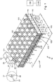
- Fig. 1 shows a laboratory automation system 10.
- the laboratory automation system 10 comprises a first laboratory station 20, a second laboratory station 30 and a laboratory sample distribution system 100.
- the laboratory automation system 10 further comprises a gripping device 25, e.g. in the form of a pick-and-place device.
- the laboratory sample distribution system 100 comprises a transport plane 110. Under the transport plane 110, a plurality of electro-magnetic actuators 120 are arranged in rows and columns. Each electro-magnetic actuator 120 comprises a respective ferromagnetic core 125.
- a number of magnetic position sensors 130 being embodied as Hall-sensors, are distributed in rows and columns over the transport plane 110.
- the laboratory sample distribution system 100 further comprises a number of sample container carriers 140.
- a sample container carrier 140 can carry a respective sample container 145, being embodied as laboratory sample tube. It is to be noted that only a single laboratory sample container carrier 140 carrying a respective sample container 145 is shown in fig. 1 for exemplary purposes.
- a typical sample distribution system 100 comprises a plurality of sample container carriers 140.
- Each sample container carrier 140 comprises a magnetically active device 141 in the form of a permanent magnet.
- magnetic fields generated by the electro-magnetic actuators 120 can drive a sample container carrier 140 over the transport plane 110.
- the magnetic field generated by the permanent magnet 141 of a sample container carrier 140 can be detected by the position sensors 130, so that a feedback regarding the position of a sample container carrier 140 can be obtained.
- Both the electro-magnetic actuators 120 and the position sensors 130 are electrically connected to a control device 150.
- the control device 150 can drive the electro-magnetic actuators 120 such that the sample container carriers 140 move along corresponding transport paths.
- the control device 150 can also determine the position of each sample container carrier 140.
- the laboratory stations 20, 30 are arranged adjacent to the transport plane 110. It is noted that these two laboratory stations 20, 30 are only shown for exemplary purposes in fig. 1 , and that a typical laboratory automation system 10 may comprise more than two laboratory stations 20, 30.
- the gripping device 25 in the form of a robot arm Adjacent to the first laboratory station 20, the gripping device 25 in the form of a robot arm is provided.
- the gripping device 25 currently carries a position determining device 27 in the form of a pen being held in a vertical orientation.
- the position determining device 27 comprises a magnetically active device 28 in the form of a permanent magnet at its lower end.
- a specific one of the electro-magnetic actuators 120 Adjacent to the first laboratory station 20, a specific one of the electro-magnetic actuators 120 is defined as a handover electro-magnetic actuator 121. If a sample container 145 is to be brought to or collected from the first laboratory station 20, a sample container carrier 140 carrying the specific sample container 145 is moved to and then held by the handover electro-magnetic actuator 121. The sample container 145 is to be gripped by the gripping device 25 and is then to be handed over to the first laboratory station 20. The same principle works basically in reverse order when a sample container 145 is to be collected from the first laboratory station 20 and is to be transported away by a sample container carrier 140.
- the gripping device 25 When the first laboratory station 20 is placed adjacent to the laboratory sample distribution system 100 for the first time, the gripping device 25 will typically also be placed at its designated position. Then, the gripping device 25 has to be calibrated so that it can grip a sample container 145 being contained in a sample container carrier 140 that has been moved on the handover electro-magnetic actuator 121. This is done using the position determining device 27, as will be explained below with respect to fig. 2 .
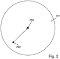
- Fig. 2 shows a top view on the horizontal surface of the handover electro-magnetic actuator 121 for illustrating an embodiment of the inventive method that can be performed using the gripping device 25. It is to be understood that the method is controlled by the control device 150, which also takes over the function of a process control unit. In other words, the control device 150 also embodies a process control unit.
- the position determining device 27 is placed automatically at a starting position 200.
- This starting position 200 will subsequently be determined using the position sensors 130 that are distributed over the transport plane 110.
- the position sensors are not only able to binary detect presence or non-presence of a sample container carrier 140, but are further adapted to provide a signal indicating a precise current magnetic field strength at the position of the respective position sensor 130.
- the position sensors 130 adjacent to (or encircling) the handover electro-magnetic actuator 121 are used. By means of the signals generated by these position sensors 130, the control device 150 is able to exactly calculate the starting position 200.
- a handover position 250 i.e. the position at which the sample container carrier 140 will come to rest with its center when it is moved over the handover electro-magnetic actuator 121, is defined at the center of the handover electro-magnetic actuator 121 (center position of the handover electro-magnetic actuator 121). This case is also shown in fig. 2 .
- the handover position 250 is in the present case identical to the center position of the handover electro-magnetic actuator 121 in top view.
- the control device 150 determines the difference between the two positions 200, 250, that is shown by a vector in fig. 2 . This difference will subsequently be used in order to calculate the handover position 250 in a Cartesian coordinate system of the gripping device 25. This allows for a correction of the position at which the gripping device 25 is placed, yielding a new starting position being practically identical to the handover position 250.
- the gripping device 25 can be operated to place the position determining device 27 at the newly determined starting position 200 and the position can be determined again. This allows for a further determination of a correction, i.e. a refinement. Such refinements can be repeated e.g. until a desired accuracy is reached and/or a determined correction is less than a certain threshold.
- the gripping device is moved to the determined handover position 250 and can thus grip correctly the sample container 145 being contained in the sample container carrier 140.
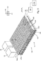
- Fig. 3 shows a laboratory automation system 10 comprising a laboratory sample distribution system 100 according to a further embodiment.
- the laboratory sample distribution system 100 comprises a number of position sensors 1500 coupled to a position determination unit 1700.
- the position sensors 1500 may be used instead of or on conjunction with the position sensors 130 depicted in fig. 1 .
- the position sensors 1500 are stationary arranged below the transport plane 110.
- Each of the position sensors 1500 has a sensing region 1600 and has an electrical resistance Rx, Ry.
- the electrical resistance Rx, Ry in particular a value of the electrical resistance Rx, Ry, is dependent on a position PS of a sample container carrier 140 on the transport plane 110 located in the sensing region 1600 of a respective position sensor 1500.
- the position determination unit 1700 is adapted to determine the positions PS of the sample container carriers 140 on top of the transport plane 110 by evaluating the electrical resistances Rx, Ry, in particular the electrical resistance values, of the position sensors 1500.
- each position sensor 1500 extends in two directions x, y being perpendicular to each other on the transport plane 110.
- the sensing region 1600 comprises a sensing area on the transport plane 110.
- each of the position sensors 1500 has an electrical resistance Rx and an electrical resistance value, respectively, for a first direction x and has an electrical resistance Ry and an electrical resistance value, respectively, for a second direction y, as depicted in figs. 5b and 5c .
- each of the position sensors 1500 has a given sensor length Lx in the first direction x along the transport plane 110 and has a given sensor length Ly in the second direction y along the transport plane 110, as depicted in figs. 4 and 5a .
- the sensor lengths Lx, Ly define the sensing region 1600 of the respective position sensor 1500.
- the electrical resistance Rx in the first direction x is dependent on the position PS of the sample container carrier 140 on the transport plane 110 located in the sensing region 1600 along the sensor length Lx.
- the electrical resistance Ry in the second direction y is dependent on the position PS of the sample container carrier 140 on the transport plane 110 located in the sensing region 1600 along the sensor length Ly.
- each of the sensor lengths Lx, Ly is 40 mm. These sensor lengths correspond to a diameter of each sample container carrier 140 on the transport plane 110.
- the position sensor 1500 comprises a resistance element 2100.
- the resistance element 2100 extends over the sensor length Lx in the first direction x along or parallel to the transport plane 110 and extends over the sensor length Ly in the second direction y along or parallel to the transport plane 110.
- the position sensor 1500 comprises a conductance element 2200.
- the conductance element 2200 is adapted to make a position-changeable electrical contact 2300 with the resistance element 2100, such that the electrical resistances Rx, Ry are caused.
- a position PC of the electrical contact 2300 along the resistance element 2100 is dependent on the position PS of the sample container carrier 140 on the transport plane 110 located in the sensing region 1600 along the resistance element 2100.
- the position sensor 1500 comprises a spatially deflectable element 1900.
- a spatial deflection of the spatially deflectable element 1900 is dependent on the position PS of the sample container carrier 140 located in the sensing region 1600.
- the electrical resistances Rx, Ry are dependent on the spatial deflection.
- the spatially deflectable element 1900 is formed by the conductance element 2200.
- the spatial deflection of the spatially deflectable element 1900 causes the position-changeable electrical contact 2300.
- the spatially deflectable element 1900 and the conductance element 2200, respectively, are embodied as a flexible membrane.
- the conductance element 2200 extends over the sensor length Lx in the first direction x along or parallel to the transport plane 110 and the resistance element 2100 and extends over the sensor length Ly in the second direction y along or parallel to the transport plane 110 and the resistance element 2100.
- the position sensor 1500 comprises a housing 2900.
- the resistance element 2100 and the conductance element 2200 are arranged inside of the housing 2900 parallel to each other separated by an air gap.
- the housing 2900 is arranged below the transport plane 110 with the resistance element 2100 being closer to the transport plane 110 than the conductance element 2200.
- the as the flexible membrane embodied conductance element 2200 is fixed or clamped at its border or edge to the housing 2900.
- the spatially deflectable element 1900 and the conductance element 2200 comprise a magnetic material 2000.
- the magnetic material 2000 is adapted to interact or interacts with the magnetically active device 141 of the sample container carrier 140 located in the sensing region 1600, such that the spatial deflection is caused.
- the magnetic material 2000 comprises magnetically soft material in the form of iron beads, wherein the iron beads are integrated into the flexible membrane.
- the spatially deflectable element may be formed by the resistance element.
- the resistance element may be embodied as a flexible membrane.
- a housing may be arranged with the conductance element being closer to the transport plane than the resistance element.
- the resistance element may comprise a magnetic material, wherein the magnetic material may be adapted to interact or may interact with the magnetically active device of the sample container carrier located in the sensing region, such that a spatial deflection of the resistance element may be caused and the position-changeable electrical contact with the conductance element may be made.
- a magnetic strength of both, the magnetically active device 141 of the sample container carrier 140 and the magnetic material 2000 of the spatially deflectable element 1900 is chosen such that the magnetic material 2000 is attracted by the magnetically active device 141 such that the conductance element 2200 is spatially deflected perpendicular to the transport plane 110 towards the resistance element 2100 into electrical contact with it, when the sample container carrier 140 on the transport plane 110 is located in the sensing region 1600 of the position sensor 1500, wherein the spatial deflection occurs at and below, respectively, the position PS of the sample container carrier 140 on the transport plane 110 and not elsewhere.
- the position-changeable electrical contact 2300 is made at the position PC, which corresponds to the position PS of the sample container carrier 140.
- the spatially deflectable element is in a first deflection state or electrical contact deflection state.
- the resistance element 2100 comprises a resistance material, which is uniform along the sensor lengths Lx, Ly.
- the position sensor 1500 comprises a first electrical contact element 2360.
- the first electrical contact element 2360 electrically contacts the resistance element 2100 at an end, in fig. 5a on the left.
- the electrical resistance Rx in the first direction x is caused in between the first electrical contact element 2360 and the conductance element 2200 with its position-changeable electrical contact 2300.
- the position sensor 1500 comprises a conductance contact element 2350.
- the conductance contact element 2350 electrically contacts the conductance element 2200.
- the conductance element 2200 comprises a conductance material, wherein an electrical resistance of the conductance element 2200 and an electrical resistivity of the conductance material, respectively, is negligibly or insignificantly small compared to an electrical resistance of the resistance element 2100 and to an electrical resistivity of the resistance material, respectively. Thereby, an electrical resistance in between the conductance contact element 2350 and the position-changeable electrical contact 2300 is negligibly or insignificantly small compared to the electrical resistance Rx.
- the position sensor 1500 comprises a second electrical contact element 2380. The second electrical contact element 2380 electrically contacts the resistance element 2100 at an opposite end than the first electrical contact element 2360, in fig. 5a on the right.
- a given voltage is applied in between the first electrical contact element 2360 and the second electrical contact element 2380, e.g. 3,3 Volts (V), in particular in the first direction x.
- a resulting voltage drop is evaluated or measured analog in between the conductance contact element 2350 and the first electrical contact element 2360, in particular in the first direction x, wherein the evaluated voltage drop is a measure for the electrical resistance Rx in the first direction x.
- This arrangement may also be denoted as potentiometer.
- the conductance element 2200 may also be denoted as voltage tap.
- the electrical resistance Rx may also be denoted as longitudinal electrical resistance.
- the position sensor 1500 comprises a third electrical contact element 2370.
- the third electrical contact element 2370 electrically contacts the resistance element 2100 at an end, in fig. 5a on the bottom.
- the electrical resistance Ry in the second direction y is caused in between the second electrical contact element 2370 and the conductance element 2200 with its position-changeable electrical contact 2300.
- An electrical resistance in between the conductance contact element 2350 and the position-changeable electrical contact 2300 is negligibly small compared to the electrical resistance Ry.
- the position sensor 1500 comprises a fourth electrical contact element 2390.
- the fourth electrical contact element 2390 electrically contacts the resistance element 2100 at an opposite end than the third electrical contact element 2370, in fig. 5a on the top.
- the given voltage is applied in between the third electrical contact element 2370 and the fourth electrical contact element 2390.
- a resulting voltage drop is evaluated analog in between the conductance contact element 2350 and the third electrical contact element 2370, wherein the evaluated voltage drop is a measure for the electrical resistance Ry in the second direction y.
- the electrical resistance Ry may also be denoted as longitudinal electrical resistance.
- the position sensor 1500 comprises a multiplexer 2400 for determination of the electrical resistance Rx, Ry in the first direction x and in the second direction y.
- the given voltage is applied in between the first electrical contact element 2360 and the second electrical contact element 2380 by the multiplexer 2400 and the electrical resistance Rx is determined, while no voltage is applied in between the third electrical contact element 2370 and the fourth electrical contact element 2390.
- the given voltage is applied in between the third electrical contact element 2370 and the fourth electrical contact element 2390 by the multiplexer 2400 and the electrical resistance Ry is determined, while no voltage is applied in between the first electrical contact element 2360 and the second electrical contact element 2380.
- the multiplexer 2400 enables to determine or to measure the electrical resistance Rx in the first direction x independent from the electrical resistance Ry in the second direction y.
- the electrical resistances Rx, Ry are unambiguously assigned to the position PS of the sample container carrier 140 on the transport plane 110 located in the sensing region 1600 of the respective position sensor 1500.
- the electrical resistance Rx in the first direction x increases with the position-changeable electrical contact 2300 moving from the left to the right in fig. 5a .
- the electrical resistance Ry in the second direction y increases with the position-changeable electrical contact 2300 moving from the bottom to the top in fig. 5a .
- the electrical resistance Rx is larger than the electrical resistance Ry and both are almost at maximum. Hence, the position PS of the sample container carrier 140 located in the sensing region 1600 of the respective position sensor 1500 is unambiguously determined by the position determination unit 1700.
- the spatially deflectable element 1900 is in a second deflection state or default deflection state.
- the position-changeable electrical contact 2300 is not present. In this case, the electrical resistances Rx, Ry each have an extreme value.
- the position sensors 1500 are arranged in rows 2500 and columns 2600, in particular quadratically.
- the rows and columns form a grid.
- the grid of the position sensors 1500 corresponds or is aligned to the grid of the electro-magnetic actuators 120.
- the sensing regions 1600 of neighboring position sensors 1500 do not overlap, but are seamlessly adjoined. Thereby, the whole transport plane 110 is captured. From the known positons of the positions sensors 1500 below the transport plane 110 and the evaluation of their electrical resistances Rx, Ry the positions PS of the sample container carriers 140 on top of the transport plane 110 are determined by the position determination unit 1700.
- the position sensors 1500 are arranged in between the transport plane 110 and the electro-magnetic actuators 120, in particular in a plane parallel to the transport plane 110, as depicted in fig. 6 .
- the laboratory sample distribution system 100 comprises a printed circuit board 2700.
- the printed circuit board 2700 is stationary arranged below the transport plane 110.
- Each of the position sensors 1500 is embodied as a surface-mount device and is mounted directly onto a surface 2800 of the printed circuit board 2700.
- the laboratory sample distribution system 100 comprises the control unit 150, as already depicted in fig. 1 .
- the control unit 150 is in signal connection with the position determination unit 1700.
- the control unit 150 is configured to control the movements of the sample container carriers 140 on top of the transport plane 110 by driving the electro-magnetic actuators 120 dependent on the positions PS of the sample container carriers 140 on top of the transport plane 110 such that the sample container carriers 140 can independently and simultaneously move along the transport paths.
- the position sensors and the position determination unit enable improved sample container carrier position detection on the transport plane.
- the first position and/or the second position may be determined by means of the position sensors 1500.
Landscapes
- Health & Medical Sciences (AREA)
- Engineering & Computer Science (AREA)
- Life Sciences & Earth Sciences (AREA)
- Physics & Mathematics (AREA)
- Chemical & Material Sciences (AREA)
- Biomedical Technology (AREA)
- General Physics & Mathematics (AREA)
- Immunology (AREA)
- Pathology (AREA)
- General Health & Medical Sciences (AREA)
- Biochemistry (AREA)
- Analytical Chemistry (AREA)
- General Engineering & Computer Science (AREA)
- Food Science & Technology (AREA)
- Medicinal Chemistry (AREA)
- Urology & Nephrology (AREA)
- Molecular Biology (AREA)
- Hematology (AREA)
- Optics & Photonics (AREA)
- Biophysics (AREA)
- Robotics (AREA)
- Mechanical Engineering (AREA)
- Automatic Analysis And Handling Materials Therefor (AREA)
- Non-Mechanical Conveyors (AREA)
Applications Claiming Priority (1)
| Application Number | Priority Date | Filing Date | Title |
|---|---|---|---|
| EP16175566.5A EP3260867A1 (de) | 2016-06-21 | 2016-06-21 | Verfahren zur bestimmung einer übergabeposition und laborautomatisierungssystem |
Publications (2)
| Publication Number | Publication Date |
|---|---|
| EP3260868A1 true EP3260868A1 (de) | 2017-12-27 |
| EP3260868B1 EP3260868B1 (de) | 2019-04-03 |
Family
ID=56368787
Family Applications (2)
| Application Number | Title | Priority Date | Filing Date |
|---|---|---|---|
| EP16175566.5A Withdrawn EP3260867A1 (de) | 2016-06-21 | 2016-06-21 | Verfahren zur bestimmung einer übergabeposition und laborautomatisierungssystem |
| EP17177008.4A Active EP3260868B1 (de) | 2016-06-21 | 2017-06-20 | Verfahren zur bestimmung einer übergabeposition und laborautomatisierungssystem |
Family Applications Before (1)
| Application Number | Title | Priority Date | Filing Date |
|---|---|---|---|
| EP16175566.5A Withdrawn EP3260867A1 (de) | 2016-06-21 | 2016-06-21 | Verfahren zur bestimmung einer übergabeposition und laborautomatisierungssystem |
Country Status (4)
| Country | Link |
|---|---|
| US (1) | US10197555B2 (de) |
| EP (2) | EP3260867A1 (de) |
| JP (1) | JP6949571B2 (de) |
| CN (1) | CN107525939B (de) |
Cited By (1)
| Publication number | Priority date | Publication date | Assignee | Title |
|---|---|---|---|---|
| WO2023214025A1 (en) | 2022-05-06 | 2023-11-09 | F. Hoffmann-La Roche Ag | Position tracking system and method for tracking a relative position of connected modules |
Families Citing this family (46)
| Publication number | Priority date | Publication date | Assignee | Title |
|---|---|---|---|---|
| DE102010028769A1 (de) | 2010-05-07 | 2011-11-10 | Pvt Probenverteiltechnik Gmbh | System zum Transportieren von Behältern zwischen unterschiedlichen Stationen und Behälterträger |
| EP2589968A1 (de) | 2011-11-04 | 2013-05-08 | Roche Diagnostics GmbH | Laborprobenverteilungssystem, Laborsystem und Betriebsverfahren |
| EP2589967A1 (de) | 2011-11-04 | 2013-05-08 | Roche Diagnostics GmbH | Laborprobenverteilungssystem und entsprechendes Betriebsverfahren |
| EP2927625A1 (de) | 2014-03-31 | 2015-10-07 | Roche Diagniostics GmbH | Probenverteilungssystem und Laborautomatisierungssystem |
| EP2977766A1 (de) | 2014-07-24 | 2016-01-27 | Roche Diagniostics GmbH | Laborprobenverteilungssystem und Laborautomatisierungssystem |
| EP2995580A1 (de) | 2014-09-09 | 2016-03-16 | Roche Diagniostics GmbH | Laborprobenverteilungssystem und Laborautomatisierungssystem |
| US9952242B2 (en) | 2014-09-12 | 2018-04-24 | Roche Diagnostics Operations, Inc. | Laboratory sample distribution system and laboratory automation system |
| EP2995958A1 (de) | 2014-09-15 | 2016-03-16 | Roche Diagniostics GmbH | Verfahren zum Betrieb einer Laborprobe Verteilungssystem, Laborprobenverteilungssystems und Laborautomatisierungssystem |
| EP3016116A1 (de) | 2014-11-03 | 2016-05-04 | Roche Diagniostics GmbH | Leiterplattenanordnung, Spule für ein Laborprobenverteilungssystem, Laborprobenverteilungssystem und Laborautomatisierungssystem |
| EP3070479B1 (de) | 2015-03-16 | 2019-07-03 | Roche Diagniostics GmbH | Transportträger, laborfrachtverteilungssystem und laborautomatisierungssystem |
| EP3537160B1 (de) | 2015-03-23 | 2020-08-12 | Roche Diagnostics GmbH | Laborprobenverteilungssystem und laborautomatisierungssystem |
| EP3095739A1 (de) | 2015-05-22 | 2016-11-23 | Roche Diagniostics GmbH | Verfahren zum betrieb eines laborprobenverteilungssystems, laborprobenverteilungssystem und laborautomatisierungssystem |
| EP3096145B1 (de) | 2015-05-22 | 2019-09-04 | Roche Diagniostics GmbH | Verfahren zum betrieb eines laborautomatisierungssystems und laborautomatisierungssystem |
| EP3096146A1 (de) | 2015-05-22 | 2016-11-23 | Roche Diagniostics GmbH | Verfahren zum betrieb eines laborprobenverteilungssystems, laborprobenverteilungssystem und laborautomatisierungssystem |
| EP3112874A1 (de) | 2015-07-02 | 2017-01-04 | Roche Diagnostics GmbH | Speichermodul, verfahren zum betrieb eines laborautomatisierungssystems und laborautomatisierungssystem |
| EP3121603A1 (de) | 2015-07-22 | 2017-01-25 | Roche Diagnostics GmbH | Probenbehälterträger, laborprobenverteilungssystem und laborautomatisierungssystem |
| EP3139175B1 (de) | 2015-09-01 | 2021-12-15 | Roche Diagnostics GmbH | Laborfrachtverteilungssystem, laborautomatisierungssystem und verfahren zum betrieb eines laborfrachtverteilungssystems |
| EP3153866A1 (de) | 2015-10-06 | 2017-04-12 | Roche Diagnostics GmbH | Verfahren zur bestimmung einer übergabeposition und laborautomatisierungssystem |
| EP3156352B1 (de) | 2015-10-13 | 2019-02-27 | Roche Diagniostics GmbH | Laborprobenverteilungssystem und laborautomatisierungssystem |
| EP3156353B1 (de) | 2015-10-14 | 2019-04-03 | Roche Diagniostics GmbH | Verfahren zum drehen eines probenbehälterträgers, laborprobenverteilungssystem und laborautomatisierungssystem |
| EP3211428A1 (de) | 2016-02-26 | 2017-08-30 | Roche Diagnostics GmbH | Transportvorrichtungseinheit für ein laborprobenverteilungssystem |
| EP3211430A1 (de) | 2016-02-26 | 2017-08-30 | Roche Diagnostics GmbH | Transportvorrichtung mit grundplattenmodulen |
| EP3211429A1 (de) | 2016-02-26 | 2017-08-30 | Roche Diagnostics GmbH | Transportvorrichtung mit gefliester fahroberfläche |
| CN109196363A (zh) | 2016-06-03 | 2019-01-11 | 豪夫迈·罗氏有限公司 | 实验室样品分配系统和实验室自动化系统 |
| EP3255519B1 (de) | 2016-06-09 | 2019-02-20 | Roche Diagniostics GmbH | Laborprobenverteilungssystem und verfahren zum betrieb eines laborprobenverteilungssystems |
| JP6752350B2 (ja) | 2016-08-04 | 2020-09-09 | エフ.ホフマン−ラ ロシュ アーゲーF. Hoffmann−La Roche Aktiengesellschaft | ラボラトリ試料分配システム及びラボラトリ自動化システム |
| EP3330717B1 (de) | 2016-12-01 | 2022-04-06 | Roche Diagnostics GmbH | Laborprobenverteilungssystem und laborautomatisierungssystem |
| EP3343232B1 (de) | 2016-12-29 | 2021-09-15 | Roche Diagnostics GmbH | Laborprobenverteilungssystem und laborautomatisierungssystem |
| EP3355065B1 (de) | 2017-01-31 | 2021-08-18 | Roche Diagnostics GmbH | Laborprobenverteilungssystem und laborautomatisierungssystem |
| EP3357842B1 (de) | 2017-02-03 | 2022-03-23 | Roche Diagnostics GmbH | Laborautomatisierungssystem |
| EP3410123B1 (de) | 2017-06-02 | 2023-09-20 | Roche Diagnostics GmbH | Verfahren zum betrieb eines laborprobenverteilungssystems, laborprobenverteilungssystem und laborautomatisierungssystem |
| EP3428653B1 (de) | 2017-07-13 | 2021-09-15 | Roche Diagnostics GmbH | Verfahren zum betreiben eines laborprobenverteilungssystems, laborprobenverteilungssystem und laborautomatisierungssystem |
| EP3457144B1 (de) | 2017-09-13 | 2021-10-20 | Roche Diagnostics GmbH | Probenbehälterträger, laborprobenverteilungssystem und laborautomatisierungssystem |
| EP3456415B1 (de) | 2017-09-13 | 2021-10-20 | Roche Diagnostics GmbH | Probenbehälterträger, laborprobenverteilungssystem und laborautomatisierungssystem |
| EP3537159B1 (de) | 2018-03-07 | 2022-08-31 | Roche Diagnostics GmbH | Verfahren zum betrieb eines laborprobenverteilungssystems, laborprobenverteilungssystem und laborautomatisierungssystem |
| EP3540443B1 (de) | 2018-03-16 | 2023-08-30 | Roche Diagnostics GmbH | Laborsystem, laborprobenverteilungssystem und laborautomationssystem |
| JP7323410B2 (ja) * | 2019-10-01 | 2023-08-08 | 株式会社日立ハイテク | 搬送装置、および分析システム |
| JP7543000B2 (ja) | 2020-06-09 | 2024-09-02 | 株式会社日立ハイテク | 搬送装置、および分析システム |
| EP3925911B1 (de) | 2020-06-19 | 2023-05-24 | Roche Diagnostics GmbH | Laborprobenverteilungssystem und entsprechendes verfahren zum betrieb |
| EP3940388B1 (de) | 2020-07-15 | 2024-04-10 | Roche Diagnostics GmbH | Laborprobenverteilungssystem und verfahren zum betrieb davon |
| EP4001923B1 (de) | 2020-11-23 | 2024-06-05 | Roche Diagnostics GmbH | Laborprobenverteilungssystem und laborautomatisierungssystem |
| US11747356B2 (en) | 2020-12-21 | 2023-09-05 | Roche Diagnostics Operations, Inc. | Support element for a modular transport plane, modular transport plane, and laboratory distribution system |
| JP7427114B2 (ja) * | 2020-12-23 | 2024-02-02 | 株式会社日立ハイテク | 検体搬送装置、および検体の搬送方法 |
| JP7422652B2 (ja) | 2020-12-24 | 2024-01-26 | 株式会社日立ハイテク | 検体搬送装置 |
| JP7805104B2 (ja) * | 2021-04-12 | 2026-01-23 | 株式会社日立ハイテク | 搬送装置、及び検体分析システム |
| EP4577838A4 (de) * | 2022-08-24 | 2025-12-24 | Siemens Healthcare Diagnostics Inc | Zustandsschätzung mit spärlicher hallsensorbasierter erfassung |
Citations (3)
| Publication number | Priority date | Publication date | Assignee | Title |
|---|---|---|---|---|
| EP2589966A1 (de) * | 2011-11-04 | 2013-05-08 | Roche Diagnostics GmbH | Laborprobenverteilungssystem und entsprechendes Betriebsverfahren |
| EP2589968A1 (de) * | 2011-11-04 | 2013-05-08 | Roche Diagnostics GmbH | Laborprobenverteilungssystem, Laborsystem und Betriebsverfahren |
| US20150233957A1 (en) * | 2014-02-17 | 2015-08-20 | Roche Diagnostics Operations, Inc. | Transport device, sample distribution system and laboratory automation system |
Family Cites Families (242)
| Publication number | Priority date | Publication date | Assignee | Title |
|---|---|---|---|---|
| US3273727A (en) | 1966-09-20 | Load handling apparatus | ||
| US3653485A (en) | 1971-03-05 | 1972-04-04 | Transportation Technology | An air bearing conveyor |
| US3901656A (en) | 1972-08-24 | 1975-08-26 | American Monitor Corp | Apparatus and method for preparing and presenting serum chemistries for analyzation |
| DE2722865C2 (de) | 1977-05-20 | 1986-06-19 | Krupp Polysius Ag, 4720 Beckum | Rohrpostförderanlage für Feingutproben |
| US4150666A (en) | 1977-06-27 | 1979-04-24 | Sherwood Medical Industries Inc. | Tube holder for blood collection tubes of different sizes |
| SU685591A1 (ru) | 1977-08-01 | 1979-09-15 | Украинский Государственный Институт По Проектированию Металлургических Заводов | Патрон пневмопочты |
| JPS56147209A (en) | 1980-04-16 | 1981-11-16 | Hitachi Kiden Kogyo Ltd | Automatic steering method for unattended carrying vehicle |
| US4544068A (en) | 1983-08-16 | 1985-10-01 | The United States Of America As Represented By The Administrator Of The National Aeronautics And Space Administration | Laboratory glassware rack for seismic safety |
| JPS60223481A (ja) | 1984-04-18 | 1985-11-07 | Nippon Telegr & Teleph Corp <Ntt> | 磁気浮上案内装置 |
| JPH0761814B2 (ja) | 1984-09-10 | 1995-07-05 | 三菱化学株式会社 | 搬送装置 |
| JPS6181323A (ja) | 1984-09-27 | 1986-04-24 | Mitsubishi Chem Ind Ltd | 整列物体の移動装置 |
| GB2165515A (en) | 1984-10-12 | 1986-04-16 | Mitsubishi Chem Ind | Conveyor |
| JPS6194925A (ja) | 1984-10-12 | 1986-05-13 | Mitsubishi Chem Ind Ltd | 搬送用装置 |
| JPS61217434A (ja) | 1985-03-20 | 1986-09-27 | Mitsubishi Chem Ind Ltd | 搬送用装置 |
| JPS61174031A (ja) | 1985-01-29 | 1986-08-05 | Youichi Oohira | リニア誘導モ−タ形x−yアクチユエ−タを用いた分岐を目的とする搬送装置 |
| JPS62100161A (ja) | 1985-10-23 | 1987-05-09 | Shin Etsu Chem Co Ltd | 平面モ−タ |
| US4771237A (en) | 1986-02-19 | 1988-09-13 | Panametrics | Method and apparatus for calibrating a displacement probe using a polynomial equation to generate a displacement look-up table |
| JPH0338704Y2 (de) | 1986-04-30 | 1991-08-15 | ||
| JPS6331918A (ja) | 1986-07-16 | 1988-02-10 | フエコ・エンジニア−ド・システムズ・インコ−ポレ−テツド | 回転および引込可能な容器保持装置およびそのコンベア |
| JPS6348169A (ja) | 1986-08-14 | 1988-02-29 | Fuji Elelctrochem Co Ltd | 圧電アクチユエ−タ |
| JPH0239554Y2 (de) | 1986-11-15 | 1990-10-23 | ||
| JPS63290101A (ja) | 1987-05-22 | 1988-11-28 | Toshiba Corp | リニアモ−タ式搬送装置 |
| JPH01148966A (ja) | 1987-12-04 | 1989-06-12 | Hitachi Kiden Kogyo Ltd | 検体搬送装置 |
| JPH01266860A (ja) | 1988-04-19 | 1989-10-24 | Yukitaka Furukawa | 試験管を冷却することが出来る試験管保持器具 |
| JP2585747B2 (ja) | 1988-09-21 | 1997-02-26 | 株式会社ダイフク | リニアモータ利用の搬送設備 |
| JPH02163637A (ja) | 1988-12-16 | 1990-06-22 | Fuji Photo Film Co Ltd | 液体化学分析装置 |
| DE3909786A1 (de) | 1989-03-24 | 1990-09-27 | Schlafhorst & Co W | Vorrichtung zum transportieren von kopsen und huelsen zwischen im verlauf des transportes wechselnden ebenen |
| DE4011797C2 (de) | 1989-06-10 | 1998-02-12 | Schlafhorst & Co W | Transportsystem für eine automatische Textilmaschine zum gesteuerten Führen von Paletten entlang vorgegebener Transportwege |
| JPH03112393A (ja) | 1989-09-21 | 1991-05-13 | Kao Corp | 搬送装置 |
| JPH03192013A (ja) | 1989-12-21 | 1991-08-21 | Toshiba Corp | 表示装置 |
| JP2973133B2 (ja) | 1990-09-19 | 1999-11-08 | 株式会社日立製作所 | 臨床検査用検体振り分け装置 |
| EP0529157A1 (de) | 1991-08-22 | 1993-03-03 | Mitsubishi Jukogyo Kabushiki Kaisha | Wechselstrom-Transportsystem mit magnetischer Schwebewirkung |
| JPH0569350A (ja) | 1991-09-11 | 1993-03-23 | Toshiba Corp | 軌道走行式ロボツト設備の保全装置 |
| JP3047571B2 (ja) | 1991-11-20 | 2000-05-29 | 株式会社日立製作所 | 臨床検査用装置 |
| JPH05180847A (ja) | 1991-12-31 | 1993-07-23 | Hiranuma Sangyo Kk | 自動分析装置用サイクラ |
| DE69308493T2 (de) | 1992-06-29 | 1997-10-23 | Dade Int Inc | Träger für proberöhrchen |
| EP0648698B1 (de) | 1992-07-07 | 1998-01-07 | Ebara Corporation | Durch magnetische wirkung schwebende transportvorrichtung |
| JPH0626808A (ja) | 1992-07-09 | 1994-02-04 | Ebara Corp | センサターゲット |
| EP0590222A1 (de) | 1992-09-30 | 1994-04-06 | STMicroelectronics S.r.l. | Magnetischer Lagegeber |
| EP0601213A1 (de) | 1992-10-29 | 1994-06-15 | Hamilton Bonaduz AG | Vorrichtung zum Transportieren von Waren |
| JPH06148198A (ja) | 1992-11-05 | 1994-05-27 | Hitachi Ltd | 分析機器の汚染防止装置 |
| JPH06156730A (ja) | 1992-11-13 | 1994-06-03 | Ebara Corp | 搬送装置 |
| JPH06175716A (ja) * | 1992-12-10 | 1994-06-24 | Fanuc Ltd | マニピュレータの物体把持作業における位置・姿勢補正方法 |
| JP3387951B2 (ja) | 1993-01-19 | 2003-03-17 | 株式会社荏原製作所 | 基板保管装置 |
| JPH07228345A (ja) | 1994-02-14 | 1995-08-29 | Ebara Corp | トンネル搬送装置 |
| JP2574126B2 (ja) | 1994-02-28 | 1997-01-22 | 照明 伊藤 | 検体遠心分離処理方法およびその装置 |
| JPH07301637A (ja) | 1994-04-29 | 1995-11-14 | Syst Sutatsuku:Kk | 検体搬送装置 |
| US5636548A (en) | 1994-05-16 | 1997-06-10 | Tesoro Alaska Petroleum Company | Analog hall-effect liquid level detector and method |
| US5523131A (en) | 1994-11-01 | 1996-06-04 | Innovative Premiums Inc. | Self-propelled table novelty device |
| IL118232A (en) | 1995-05-15 | 2001-07-24 | Smithkline Beecham Corp | Bottle holder |
| US5925956A (en) | 1995-06-30 | 1999-07-20 | Nikon Corporation | Stage construction incorporating magnetically levitated movable stage |
| JPH0917848A (ja) | 1995-06-30 | 1997-01-17 | Nikon Corp | 磁気浮上型ステージ |
| US5735387A (en) | 1995-07-14 | 1998-04-07 | Chiron Diagnostics Corporation | Specimen rack handling system |
| US5720377A (en) | 1995-07-14 | 1998-02-24 | Chiron Diagnostics Corporation | Magnetic conveyor system |
| EP0775650A1 (de) | 1995-11-24 | 1997-05-28 | André Dr. von Froreich | Fördersystem, insbesondere für Materialträger für den labormedizinischen Einsatz |
| US5788929A (en) | 1996-03-12 | 1998-08-04 | Nesti; Edmund D. | Sample temperature protection rack |
| US6191507B1 (en) | 1997-05-02 | 2001-02-20 | Ats Automation Tooling Systems Inc. | Modular conveyor system having multiple moving elements under independent control |
| JPH1159901A (ja) | 1997-08-11 | 1999-03-02 | Murata Mach Ltd | キャリヤー移動装置 |
| JP3444760B2 (ja) | 1997-09-11 | 2003-09-08 | 株式会社日立製作所 | 検体搬送システム |
| US6838051B2 (en) | 1999-05-03 | 2005-01-04 | Ljl Biosystems, Inc. | Integrated sample-processing system |
| US6141602A (en) | 1997-09-25 | 2000-10-31 | Hitachi, Ltd. | Specimen processing system |
| US5897090A (en) | 1997-11-13 | 1999-04-27 | Bayer Corporation | Puck for a sample tube |
| GB2331838A (en) | 1997-11-24 | 1999-06-02 | Coolbox | Portable,thermoelectric,temperature controlled receptacles. |
| JPH11264828A (ja) | 1998-03-19 | 1999-09-28 | Hitachi Ltd | 検体搬送システム |
| JPH11304812A (ja) | 1998-04-20 | 1999-11-05 | Hitachi Ltd | 検体処理システム |
| DE19819813C2 (de) | 1998-05-04 | 2000-11-02 | Olympus Diagnostica Gmbh | Verwendung eines Laborprimärprobenverteilers zum Archivieren |
| JP3301965B2 (ja) | 1998-05-19 | 2002-07-15 | アロカ株式会社 | ラベル読取り装置 |
| US6206176B1 (en) | 1998-05-20 | 2001-03-27 | Applied Komatsu Technology, Inc. | Substrate transfer shuttle having a magnetic drive |
| CA2273729A1 (en) | 1998-07-14 | 2000-01-14 | Bayer Corporation | Robotics for transporting containers and objects within an automated analytical instrument and service tool for servicing robotics |
| US6279728B1 (en) | 1998-07-20 | 2001-08-28 | Norbert G Jung | Electro-magnetic conveyor |
| JP3930977B2 (ja) | 1998-07-31 | 2007-06-13 | 株式会社日立製作所 | 検体処理システム |
| JP2000105243A (ja) | 1998-09-29 | 2000-04-11 | Hitachi Ltd | ラック搬送装置 |
| JP3668618B2 (ja) | 1998-09-29 | 2005-07-06 | 株式会社日立製作所 | 自動分析装置 |
| JP4136187B2 (ja) | 1999-05-14 | 2008-08-20 | シスメックス株式会社 | 検体移し替え装置 |
| US6062398A (en) | 1999-07-21 | 2000-05-16 | Thalmayr; Hermann | Insert for holding test tubes in a conveyor capsule of a pneumatic tube conveyor system |
| US6429016B1 (en) | 1999-10-01 | 2002-08-06 | Isis Pharmaceuticals, Inc. | System and method for sample positioning in a robotic system |
| JP3424623B2 (ja) | 1999-10-29 | 2003-07-07 | 日立エンジニアリング株式会社 | 検体仕分け装置 |
| EP1122194B1 (de) | 2000-02-01 | 2004-11-10 | Johnson & Johnson Vision Care, Inc. | Vorrichtung und Verfahren für automatisiertes Warenlager |
| JP2001240245A (ja) | 2000-03-01 | 2001-09-04 | Auto Cs Engineering Co Ltd | 圧縮空気による搬送システムおよび搬送装置 |
| US20040050836A1 (en) | 2000-09-29 | 2004-03-18 | Nesbitt Geoffrey John | Assembly of an integrated vessel transporter and at least one reaction vessel and integrated vessel transporter for transporting a chemical substance |
| DE10050085C1 (de) | 2000-10-10 | 2001-10-31 | Jochem Koetting | Verschlußelement und Verschlußsystem für Behältnisse und Gefäße |
| US6825041B2 (en) | 2001-03-16 | 2004-11-30 | Beckman Coulter, Inc. | Method and system for automated immunochemistry analysis |
| AUPR854301A0 (en) | 2001-10-29 | 2001-11-29 | Martin Gessner Pty Ltd | Conveying apparatus |
| US6571934B1 (en) | 2001-11-14 | 2003-06-03 | Dade Behring Inc. | Bi-directional magnetic sample rack conveying system |
| JP3527904B2 (ja) | 2002-02-28 | 2004-05-17 | 照明 伊藤 | 試験管ホルダー |
| JP4105164B2 (ja) | 2002-09-26 | 2008-06-25 | バイオパス・オートメーション・エル・エル・シー | 組織標本のハンドリングおよび包埋を自動化する機器および方法 |
| JP3675791B2 (ja) | 2002-11-01 | 2005-07-27 | 照明 伊藤 | バーコード化装置 |
| TWI249574B (en) | 2002-11-19 | 2006-02-21 | Sanyo Electric Co | Preserving device |
| JP3765788B2 (ja) | 2002-11-29 | 2006-04-12 | 照明 伊藤 | 検体分注システム |
| GB2402481A (en) | 2003-06-04 | 2004-12-08 | Genial Genetic Solutions Ltd | Multi-well rotatable analyser |
| US7648835B2 (en) | 2003-06-06 | 2010-01-19 | Micronics, Inc. | System and method for heating, cooling and heat cycling on microfluidic device |
| JP3910157B2 (ja) | 2003-06-11 | 2007-04-25 | ファナック株式会社 | ロボット装置 |
| DE10340143A1 (de) | 2003-08-26 | 2005-03-31 | SSI Schäfer PEEM GmbH | Kommissionierplatz und Verfahren zum Kommissionieren |
| US20050079103A1 (en) | 2003-10-14 | 2005-04-14 | Merrit Jacobs | Moving evaporation control cover |
| US6971503B2 (en) | 2003-11-26 | 2005-12-06 | Cynthia Thompson | Conveyor belt cleaning apparatus |
| JP4680935B2 (ja) | 2004-01-08 | 2011-05-11 | ジクスト、ベルンハルト | 冷凍材料の冷却保持用輸送容器 |
| US7078082B2 (en) | 2004-01-15 | 2006-07-18 | Sonoco Development, Inc. | Dual-functioning mechanism for startup during winding of web material and for splicing during unwinding |
| US7028831B2 (en) | 2004-03-05 | 2006-04-18 | Beckman Coulter, Inc. | Magnetic specimen-transport system for automated clinical instrument |
| US7331474B2 (en) | 2004-03-05 | 2008-02-19 | Beckman Coulter, Inc. | Specimen-container rack for automated clinical instrument |
| US7850914B2 (en) | 2004-03-05 | 2010-12-14 | Beckman Coulter, Inc. | Specimen-transport module for a multi-instrument clinical workcell |
| JP2005249740A (ja) | 2004-03-08 | 2005-09-15 | Olympus Corp | サンプルラック搬送装置及びサンプルラック搬送方法 |
| US7382258B2 (en) | 2004-03-19 | 2008-06-03 | Applera Corporation | Sample carrier device incorporating radio frequency identification, and method |
| WO2005092632A1 (en) | 2004-03-27 | 2005-10-06 | Microrobot Co., Ltd. | Navigation system for position self control robot and floor materials for providing absolute coordinates used thereof |
| JP3905094B2 (ja) | 2004-04-07 | 2007-04-18 | 株式会社アイディエス | 自走式検体ホルダの搬送システム |
| JP4098272B2 (ja) | 2004-04-26 | 2008-06-11 | 株式会社アイディエス | 試験管のバーコード読取り装置 |
| US20060000296A1 (en) | 2004-07-02 | 2006-01-05 | Salter Jason P | Synchronization of sample and data collection |
| JPWO2006006730A1 (ja) | 2004-07-15 | 2008-05-01 | 株式会社ニコン | 平面モータ装置、ステージ装置、露光装置及びデバイスの製造方法 |
| US7862579B2 (en) | 2004-07-28 | 2011-01-04 | Ethicon Endo-Surgery, Inc. | Electroactive polymer-based articulation mechanism for grasper |
| JP4543181B2 (ja) | 2004-12-20 | 2010-09-15 | 国立大学法人九州工業大学 | 超電導磁気浮上による非接触搬送装置 |
| US7225915B2 (en) | 2005-04-05 | 2007-06-05 | Carol Lynn Kelly | Mountable cleaning apparatus for commercial conveyors |
| US20060246576A1 (en) | 2005-04-06 | 2006-11-02 | Affymetrix, Inc. | Fluidic system and method for processing biological microarrays in personal instrumentation |
| FR2888328B1 (fr) | 2005-07-08 | 2013-09-20 | Horiba Abx Sas | Procede automatise de preparation d'analyse d'echantillons de sang total et dispositif automatise pour sa mise en oeuvre |
| US7566168B2 (en) | 2005-08-19 | 2009-07-28 | Shake Awake Products, LLC | Apparatus and method for determining the amount of time until a desired temperature is reached |
| US8346382B2 (en) | 2005-08-25 | 2013-01-01 | Coldtrack, Llc | Hierarchical sample storage system |
| US20070116611A1 (en) | 2005-11-14 | 2007-05-24 | Demarco Nicholas | Fraction collection system |
| JP4113891B2 (ja) | 2005-12-20 | 2008-07-09 | ジェイ・エス・ケー株式会社 | 静電容量型検出装置 |
| CN201045617Y (zh) | 2006-04-21 | 2008-04-09 | 北京赛科希德科技发展有限公司 | 用于全自动凝血测量的测试杯连续输送装置 |
| US7776270B2 (en) | 2006-04-25 | 2010-08-17 | Ecocap's S.R.L. | Resealer of test tubes for clinical analyses fed from ready-to-use containers of sealing tape |
| JP2007309675A (ja) | 2006-05-16 | 2007-11-29 | Olympus Corp | サンプルラック供給回収装置 |
| JP4586992B2 (ja) | 2006-05-23 | 2010-11-24 | 株式会社ダイフク | 物品処理設備 |
| JP2007322289A (ja) | 2006-06-01 | 2007-12-13 | Olympus Corp | 搬送装置 |
| US7666366B2 (en) | 2006-07-10 | 2010-02-23 | Exxonmobil Chemical Patents Inc. | Internal loop reactor and Oxo process using same |
| DE102006032435A1 (de) | 2006-07-13 | 2008-01-17 | Sixt, Bernhard, Dr. | Transportbehälter zur Kühlhaltung von gefrorenem Gut |
| JP2008058202A (ja) | 2006-08-31 | 2008-03-13 | Ids Co Ltd | 検体搬送システム |
| JP4336360B2 (ja) | 2006-09-20 | 2009-09-30 | 株式会社アイディエス | 検体前処理搬送装置 |
| DE102007013237A1 (de) | 2007-03-15 | 2008-09-18 | Joint Analytical Systems Gmbh | Lagersystem |
| DE102007014876B4 (de) | 2007-03-26 | 2010-04-08 | Kba-Metronic Aktiengesellschaft | Transportsystem |
| ES2537079T3 (es) | 2007-04-16 | 2015-06-02 | Crisplant A/S | Sistema de clasificación con un accionamiento mediante un motor lineal síncrono |
| US7681466B2 (en) | 2007-05-01 | 2010-03-23 | Siemens Healthcare Diagnostics Inc. | Programmable random access sample handler for use within and automated laboratory system |
| JP3133890U (ja) | 2007-05-16 | 2007-07-26 | 株式会社日立ハイテクノロジーズ | 検体処理システム |
| DE102007025822A1 (de) | 2007-06-02 | 2008-12-18 | Lars Bergmann | Kombinierbares Flächenelement mit einer Vielzahl von ansteuerbaren Wandlerelementen |
| EP2153295B1 (de) | 2007-06-06 | 2014-11-05 | Path | Chemische temperatursteuerung |
| CN101680548A (zh) | 2007-06-19 | 2010-03-24 | 株式会社开滋 | 轴封装置和使用该轴封装置的阀结构 |
| US8556564B2 (en) | 2007-06-26 | 2013-10-15 | Siemens Healthcare Diagnostics Inc. | Mobile sample storage and retrieval unit for a laboratory automated sample handling worksystem |
| KR101307859B1 (ko) | 2007-07-19 | 2013-09-12 | 삼성전자주식회사 | 생화학 분석기 및 그 내부 온도 제어 방법 |
| JP2009036643A (ja) | 2007-08-01 | 2009-02-19 | Astec Corp:Kk | ラックへの試験管投入パターンの制御装置 |
| JP2009062188A (ja) | 2007-09-10 | 2009-03-26 | Tsubakimoto Chain Co | リニヤ誘導モータ形x−yアクチュエータを用いた仕分装置 |
| WO2009039122A2 (en) | 2007-09-17 | 2009-03-26 | Sequenom, Inc. | Integrated robotic sample transfer device |
| US20090128139A1 (en) | 2007-11-20 | 2009-05-21 | Drenth Joseph B | Magnet position locator |
| ITMI20072254A1 (it) | 2007-11-30 | 2009-06-01 | Dachi S R L | "impianto di identificazione, trasporto ed indirizzamento automatico di campioni di materiale biologico" |
| ITMI20072255A1 (it) | 2007-11-30 | 2009-06-01 | Dachi S R L | "apparato di carico e scarico automatico di provette di materiale biologico in un impianto di posta pneumatica" |
| ITFI20070275A1 (it) | 2007-12-07 | 2009-06-08 | Diesse Diagnostica Senese Spa | "dispositivo e metodo di analisi microbiologica di campioni biologici" |
| JP4863983B2 (ja) | 2007-12-13 | 2012-01-25 | 株式会社堀場製作所 | 試験管ホルダ及び試料吸引装置 |
| JP5258306B2 (ja) | 2008-01-16 | 2013-08-07 | 株式会社ブリヂストン | ベルトモニタリングシステム |
| AT506886A1 (de) | 2008-05-16 | 2009-12-15 | Tgw Mechanics Gmbh | Verfahren und lagersystem zum konsolidieren von versandeinheiten |
| JP5140497B2 (ja) | 2008-06-17 | 2013-02-06 | ベックマン コールター, インコーポレイテッド | 分析装置及び分析方法 |
| US20110172128A1 (en) | 2008-09-12 | 2011-07-14 | Anthony Davies | Multi-well device |
| US8459462B2 (en) | 2008-10-10 | 2013-06-11 | Quest Diagnostics Investments Incorporated | System and method for sorting specimen |
| WO2010065145A1 (en) | 2008-12-05 | 2010-06-10 | Leap Technologies, Inc. | System for preparing samples for analysis using a shock freezer |
| US8616134B2 (en) | 2009-01-23 | 2013-12-31 | Magnemotion, Inc. | Transport system powered by short block linear synchronous motors |
| JP5250050B2 (ja) | 2009-01-27 | 2013-07-31 | 株式会社日立ハイテクノロジーズ | 自動分析装置および自動分析方法 |
| EP2403784B1 (de) | 2009-03-03 | 2013-07-24 | ATS Automation Tooling Systems Inc. | Multimodales fördersystem mit spiralnocke |
| JP5275119B2 (ja) | 2009-04-06 | 2013-08-28 | 日本電子株式会社 | 自動分析装置 |
| CN102461330A (zh) | 2009-05-05 | 2012-05-16 | 赛普拉斯半导体公司 | 溢出检测方法及系统 |
| GB2473868A (en) | 2009-09-28 | 2011-03-30 | Invitrogen Dynal As | Apparatus and method of automated processing of biological samples |
| WO2010132749A2 (en) | 2009-05-15 | 2010-11-18 | Biomerieux, Inc. | Automated transfer mechanism for microbial. detection apparatus |
| BE1018828A3 (nl) | 2009-07-16 | 2011-09-06 | Praet Peter Van | Intelligent rek voor specimen buisjes en werkwijze om de buisjes in het rek te laden. |
| JP5481122B2 (ja) | 2009-07-28 | 2014-04-23 | 株式会社日立ハイテクノロジーズ | 遠心分離装置 |
| US7939484B1 (en) | 2009-10-27 | 2011-05-10 | Clariant International, Ltd. | Method for reducing the adhesion forces between hard surfaces and subsequently occurring soil |
| EP2327646B1 (de) | 2009-11-26 | 2012-02-08 | GLP systems GmbH | In einem Abzweig einer Transportbahn für Laborproben in einem analytischen Labor angeordnete Weiche |
| JP5372732B2 (ja) | 2009-12-28 | 2013-12-18 | シスメックス株式会社 | 検体分析装置および検体ラック搬送方法 |
| JP2013518251A (ja) | 2010-01-21 | 2013-05-20 | シーメンス・ヘルスケア・ダイアグノスティックス・インコーポレーテッド | 可動磁石を含む磁気コンベヤシステム、装置及び方法 |
| CN104597267B (zh) | 2010-01-21 | 2016-11-23 | 希森美康株式会社 | 样本分析装置 |
| US8141695B2 (en) | 2010-01-29 | 2012-03-27 | Ecolab Usa Inc. | Clean conveyor sensing system |
| US8240460B1 (en) | 2010-02-18 | 2012-08-14 | Michael James Bleau | Apparatus for cleaning a conveyor belt |
| DE102010028769A1 (de) | 2010-05-07 | 2011-11-10 | Pvt Probenverteiltechnik Gmbh | System zum Transportieren von Behältern zwischen unterschiedlichen Stationen und Behälterträger |
| US8915421B2 (en) | 2010-08-13 | 2014-12-23 | Lear Sirous Lavi | Transfer, link, bind, specimen tube barcode information to RFID specimen transport puck in a continuous moving binding process method |
| WO2012032503A1 (en) | 2010-09-07 | 2012-03-15 | University Of Limerick | A liquid droplet dispenser |
| JP5715378B2 (ja) | 2010-10-28 | 2015-05-07 | シスメックス株式会社 | 検体処理システム |
| DE102012000665A1 (de) | 2011-02-07 | 2012-08-09 | Sew-Eurodrive Gmbh & Co. Kg | Sorter |
| IT1403938B1 (it) | 2011-02-16 | 2013-11-08 | Inpeco Ip Ltd Ora Inpeco Holding Ltd | Apparato di interfacciamento tra un impianto di posta pneumatica e un sistema di alimentazione di contenitori di prodotti biologici verso un impianto di automazione di laboratorio. |
| US8624203B2 (en) | 2011-02-23 | 2014-01-07 | JLT & Associates, Inc. | Conveyor sterilization |
| US9547945B2 (en) | 2011-03-18 | 2017-01-17 | The Raymond Corporation | Integration of an autonomous industrial vehicle into an asset management system |
| PT2502675E (pt) | 2011-03-25 | 2014-04-23 | Symbion Medical Systems S Rl | Suporte de recipiente e porta-recipiente |
| EP2518514B1 (de) | 2011-04-29 | 2014-06-18 | F. Hoffmann-La Roche AG | Verfahren zum Betreiben einer automatischen Probenarbeitszelle |
| JP6014123B2 (ja) | 2011-05-13 | 2016-10-25 | ベックマン コールター, インコーポレイテッド | 研究室生成物輸送要素および経路配列 |
| CN103518137B (zh) | 2011-05-13 | 2016-09-07 | 贝克曼考尔特公司 | 包括实验室产品传送元件的系统和方法 |
| US8920720B2 (en) | 2011-06-03 | 2014-12-30 | Rushabh Instruments, Inc. | Rotary tissue processor with configurable stations |
| WO2012170636A1 (en) | 2011-06-07 | 2012-12-13 | Magnemotion, Inc. | Versatile control of a linear synchronous motor propulsion system |
| FR2978883B1 (fr) * | 2011-08-01 | 2013-07-26 | Moving Magnet Tech | Ensemble compact de positionnement comprenant un actionneur et un capteur integre dans la culasse de l'actionneur |
| EP2755037B1 (de) | 2011-09-05 | 2024-12-25 | Hitachi High-Tech Corporation | Automatische analysevorrichtung |
| US10012664B2 (en) | 2011-09-25 | 2018-07-03 | Theranos Ip Company, Llc | Systems and methods for fluid and component handling |
| EP2589967A1 (de) | 2011-11-04 | 2013-05-08 | Roche Diagnostics GmbH | Laborprobenverteilungssystem und entsprechendes Betriebsverfahren |
| KR20140091032A (ko) | 2011-11-07 | 2014-07-18 | 베크만 컬터, 인코포레이티드 | 검체 수송 시스템의 자기 감쇠 |
| EP2589969A1 (de) * | 2011-11-07 | 2013-05-08 | Dario Maximilian Spera | Physischer Träger von biologisch aktiven Frequenzen |
| DE102011118977A1 (de) | 2011-11-19 | 2013-05-23 | Robert Bosch Gmbh | Fördervorrichtung |
| EP2799884B1 (de) | 2011-12-28 | 2018-04-25 | Hitachi High-Technologies Corporation | Halter zur übertragung von probenröhrchen |
| DE102011090044A1 (de) | 2011-12-28 | 2013-07-04 | Siemens Healthcare Diagnostics Products Gmbh | Transportsystem und Verfahren zum Betrieb |
| EP2629100B1 (de) | 2012-02-15 | 2016-09-14 | GLP systems GmbH | Fördersystem für Materialproben, insbesondere medizinische Proben |
| JP2013172009A (ja) | 2012-02-21 | 2013-09-02 | Hitachi Ltd | フローはんだ付け装置およびはんだ液面調整方法 |
| US9664431B2 (en) | 2012-03-12 | 2017-05-30 | The World Egg Bank, Inc | Cryogenic sample holder |
| JP2013190400A (ja) | 2012-03-15 | 2013-09-26 | Hitachi High-Technologies Corp | 自動分析装置 |
| EP2834648A4 (de) | 2012-04-04 | 2015-12-23 | Siemens Healthcare Diagnostics | Verfahren zur verarbeitung von prioritätsproben zur bewahrung einer fifo-verarbeitungswarteschlange |
| EP2847109B1 (de) | 2012-05-11 | 2017-12-20 | Siemens Healthcare Diagnostics Inc. | Verfahren und system zum transport von probenröhrchen |
| WO2013177087A2 (en) | 2012-05-22 | 2013-11-28 | Siemens Healthcare Diagnostics Inc. | Linear random access queue |
| JP6177895B2 (ja) | 2012-05-24 | 2017-08-09 | シーメンス・ヘルスケア・ダイアグノスティックス・インコーポレーテッドSiemens Healthcare Diagnostics Inc. | 知能オートメーションパック用非接触光エンコーディングスキーム |
| US9952241B2 (en) | 2012-08-20 | 2018-04-24 | Siemens Healthcare Diagnostics Inc. | Methods and apparatus for ascertaining specimen and/or sample container characteristics while in transit |
| CA2887643C (en) | 2012-10-11 | 2021-06-08 | Siemens Healthcare Diagnostics Inc. | Modular workcells for lab automation |
| CA2887635C (en) | 2012-10-11 | 2021-01-26 | Siemens Healthcare Diagnostics Inc. | Automation maintenance carrier |
| CA2890131C (en) | 2012-11-01 | 2020-12-29 | Siemens Healthcare Diagnostics Inc. | Multiple carrier and sleeve tray |
| CA2903013C (en) | 2013-03-08 | 2021-05-11 | Siemens Healthcare Diagnostics Inc. | Tube characterization station |
| CH708820A1 (de) | 2013-11-07 | 2015-05-15 | Tecan Trading Ag | Inkubationskassette. |
| EP2887071B1 (de) | 2013-12-19 | 2018-12-05 | F. Hoffmann-La Roche AG | Lagerung und Bereitstellung von Gefäßhaltern |
| DE102014202838B3 (de) | 2014-02-17 | 2014-11-06 | Roche Pvt Gmbh | Transportvorrichtung, Probenverteilungssystem und Laborautomatierungssystem |
| US10493457B2 (en) | 2014-03-28 | 2019-12-03 | Brooks Automation, Inc. | Sample storage and retrieval system |
| EP2927168A1 (de) | 2014-03-31 | 2015-10-07 | Roche Diagniostics GmbH | Transportvorrichtung, Probenverteilungssystem und Laborautomatisierungssystem |
| EP2927625A1 (de) | 2014-03-31 | 2015-10-07 | Roche Diagniostics GmbH | Probenverteilungssystem und Laborautomatisierungssystem |
| EP2927167B1 (de) | 2014-03-31 | 2018-04-18 | F. Hoffmann-La Roche AG | Versandvorrichtung, Probenverteilungssystem und Laborautomatisierungssystem |
| EP2927163B1 (de) | 2014-03-31 | 2018-02-28 | Roche Diagnostics GmbH | Vertikalfördervorrichtung, Probenverteilungssystem und Laborautomatisierungssystem |
| EP2927695B1 (de) | 2014-03-31 | 2018-08-22 | Roche Diagniostics GmbH | Probenverteilungssystem und Laborautomatisierungssystem |
| EP2957914B1 (de) | 2014-06-17 | 2018-01-03 | Roche Diagnostics GmbH | Laborprobenverteilungssystem und Laborautomatisierungssystem |
| EP2977765A1 (de) | 2014-07-23 | 2016-01-27 | Roche Diagniostics GmbH | Probenbehälterträger, Laborprobenverteilungssystem und Laborautomatisierungssystem |
| EP2977842A1 (de) | 2014-07-23 | 2016-01-27 | F. Hoffmann-La Roche AG | Laborprobenverteilungssystem und Laborautomatisierungssystem |
| EP2977766A1 (de) | 2014-07-24 | 2016-01-27 | Roche Diagniostics GmbH | Laborprobenverteilungssystem und Laborautomatisierungssystem |
| EP2988134A1 (de) | 2014-08-21 | 2016-02-24 | Roche Diagniostics GmbH | Probenbehälterträger für ein Laborprobenverteilungssystem, Laborprobenverteilungssystem und Laborautomatisierungssystem |
| EP2995381A1 (de) | 2014-09-09 | 2016-03-16 | Roche Diagniostics GmbH | Probenbehälterträgersatz für ein Laborprobenverteilungssystem, Laborprobenverteilungssystem und Laborautomatisierungssystem |
| EP2995960B1 (de) | 2014-09-09 | 2020-07-15 | Roche Diagniostics GmbH | Laborprobenverteilungssystem und Verfahren zur Kalibrierung von magnetischen Sensoren |
| EP2995580A1 (de) | 2014-09-09 | 2016-03-16 | Roche Diagniostics GmbH | Laborprobenverteilungssystem und Laborautomatisierungssystem |
| US9952242B2 (en) | 2014-09-12 | 2018-04-24 | Roche Diagnostics Operations, Inc. | Laboratory sample distribution system and laboratory automation system |
| EP2995958A1 (de) | 2014-09-15 | 2016-03-16 | Roche Diagniostics GmbH | Verfahren zum Betrieb einer Laborprobe Verteilungssystem, Laborprobenverteilungssystems und Laborautomatisierungssystem |
| EP3006943B1 (de) | 2014-10-07 | 2020-04-22 | Roche Diagniostics GmbH | Modul für ein Laborprobenverteilungssystem, Laborprobenverteilungssystem und Laborautomatisierungssystem |
| EP3016116A1 (de) | 2014-11-03 | 2016-05-04 | Roche Diagniostics GmbH | Leiterplattenanordnung, Spule für ein Laborprobenverteilungssystem, Laborprobenverteilungssystem und Laborautomatisierungssystem |
| EP3056907B1 (de) | 2015-02-11 | 2020-03-18 | F. Hoffmann-La Roche AG | Verfahren und vorrichtung zur handhabung von reagenzgläsern in einem laborautomatisierungssystem |
| EP3070479B1 (de) | 2015-03-16 | 2019-07-03 | Roche Diagniostics GmbH | Transportträger, laborfrachtverteilungssystem und laborautomatisierungssystem |
| EP3537160B1 (de) | 2015-03-23 | 2020-08-12 | Roche Diagnostics GmbH | Laborprobenverteilungssystem und laborautomatisierungssystem |
| EP3096145B1 (de) | 2015-05-22 | 2019-09-04 | Roche Diagniostics GmbH | Verfahren zum betrieb eines laborautomatisierungssystems und laborautomatisierungssystem |
| EP3096146A1 (de) | 2015-05-22 | 2016-11-23 | Roche Diagniostics GmbH | Verfahren zum betrieb eines laborprobenverteilungssystems, laborprobenverteilungssystem und laborautomatisierungssystem |
| EP3095739A1 (de) | 2015-05-22 | 2016-11-23 | Roche Diagniostics GmbH | Verfahren zum betrieb eines laborprobenverteilungssystems, laborprobenverteilungssystem und laborautomatisierungssystem |
| EP3112874A1 (de) | 2015-07-02 | 2017-01-04 | Roche Diagnostics GmbH | Speichermodul, verfahren zum betrieb eines laborautomatisierungssystems und laborautomatisierungssystem |
| EP3139175B1 (de) | 2015-09-01 | 2021-12-15 | Roche Diagnostics GmbH | Laborfrachtverteilungssystem, laborautomatisierungssystem und verfahren zum betrieb eines laborfrachtverteilungssystems |
| EP3153867B1 (de) | 2015-10-06 | 2018-11-14 | Roche Diagniostics GmbH | Verfahren zur konfiguration eines laborautomatisierungssystems, laborprobenverteilungssystem und laborautomatisierungssystem |
| EP3153866A1 (de) | 2015-10-06 | 2017-04-12 | Roche Diagnostics GmbH | Verfahren zur bestimmung einer übergabeposition und laborautomatisierungssystem |
| EP3156352B1 (de) | 2015-10-13 | 2019-02-27 | Roche Diagniostics GmbH | Laborprobenverteilungssystem und laborautomatisierungssystem |
| EP3156353B1 (de) | 2015-10-14 | 2019-04-03 | Roche Diagniostics GmbH | Verfahren zum drehen eines probenbehälterträgers, laborprobenverteilungssystem und laborautomatisierungssystem |
| EP3211427A1 (de) | 2016-02-25 | 2017-08-30 | Roche Diagnostics GmbH | Probenbehälterträger |
| EP3211426A1 (de) | 2016-02-25 | 2017-08-30 | Roche Diagnostics GmbH | Probenbehälterträger |
| EP3330717B1 (de) | 2016-12-01 | 2022-04-06 | Roche Diagnostics GmbH | Laborprobenverteilungssystem und laborautomatisierungssystem |
| EP3343232B1 (de) | 2016-12-29 | 2021-09-15 | Roche Diagnostics GmbH | Laborprobenverteilungssystem und laborautomatisierungssystem |
| EP3351940A1 (de) | 2017-01-24 | 2018-07-25 | Roche Diagnostics GmbH | Laboratorium |
| EP3355064A1 (de) | 2017-01-25 | 2018-08-01 | Roche Diagnostics GmbH | Laborprobenverteilungssystem und laborautomatisierungssystem |
| EP3355065B1 (de) | 2017-01-31 | 2021-08-18 | Roche Diagnostics GmbH | Laborprobenverteilungssystem und laborautomatisierungssystem |
| EP3357842B1 (de) | 2017-02-03 | 2022-03-23 | Roche Diagnostics GmbH | Laborautomatisierungssystem |
-
2016
- 2016-06-21 EP EP16175566.5A patent/EP3260867A1/de not_active Withdrawn
-
2017
- 2017-06-05 US US15/613,596 patent/US10197555B2/en active Active
- 2017-06-19 JP JP2017119386A patent/JP6949571B2/ja active Active
- 2017-06-20 EP EP17177008.4A patent/EP3260868B1/de active Active
- 2017-06-21 CN CN201710474787.9A patent/CN107525939B/zh active Active
Patent Citations (4)
| Publication number | Priority date | Publication date | Assignee | Title |
|---|---|---|---|---|
| EP2589966A1 (de) * | 2011-11-04 | 2013-05-08 | Roche Diagnostics GmbH | Laborprobenverteilungssystem und entsprechendes Betriebsverfahren |
| EP2589968A1 (de) * | 2011-11-04 | 2013-05-08 | Roche Diagnostics GmbH | Laborprobenverteilungssystem, Laborsystem und Betriebsverfahren |
| WO2013064656A1 (en) | 2011-11-04 | 2013-05-10 | Roche Diagnostics Gmbh | Laboratory sample distribution system and corresponding method of operation |
| US20150233957A1 (en) * | 2014-02-17 | 2015-08-20 | Roche Diagnostics Operations, Inc. | Transport device, sample distribution system and laboratory automation system |
Cited By (1)
| Publication number | Priority date | Publication date | Assignee | Title |
|---|---|---|---|---|
| WO2023214025A1 (en) | 2022-05-06 | 2023-11-09 | F. Hoffmann-La Roche Ag | Position tracking system and method for tracking a relative position of connected modules |
Also Published As
| Publication number | Publication date |
|---|---|
| JP6949571B2 (ja) | 2021-10-13 |
| EP3260867A1 (de) | 2017-12-27 |
| CN107525939B (zh) | 2020-09-11 |
| US10197555B2 (en) | 2019-02-05 |
| CN107525939A (zh) | 2017-12-29 |
| JP2017227635A (ja) | 2017-12-28 |
| US20170363608A1 (en) | 2017-12-21 |
| EP3260868B1 (de) | 2019-04-03 |
Similar Documents
| Publication | Publication Date | Title |
|---|---|---|
| EP3260868B1 (de) | Verfahren zur bestimmung einer übergabeposition und laborautomatisierungssystem | |
| EP3343232B1 (de) | Laborprobenverteilungssystem und laborautomatisierungssystem | |
| US10197586B2 (en) | Method of determining a handover position and laboratory automation system | |
| US9902572B2 (en) | Method of configuring a laboratory automation system, laboratory sample distribution system and laboratory automation system | |
| US9989547B2 (en) | Laboratory sample distribution system and laboratory automation system | |
| US20180224476A1 (en) | Laboratory automation system | |
| US20180210001A1 (en) | Laboratory sample distribution system and laboratory automation system | |
| EP3465225B1 (de) | Laborprobenverteilungssystem und laborautomatisierungssystem | |
| JP6055503B2 (ja) | 試料分配システムおよび実験室自動化システム | |
| US20190101468A1 (en) | Detector for a laboratory liquid distribution system, detector system for a laboratory liquid distribution system, laboratory liquid distribution system, laboratory automation system and use of a detector | |
| EP2995958A1 (de) | Verfahren zum Betrieb einer Laborprobe Verteilungssystem, Laborprobenverteilungssystems und Laborautomatisierungssystem | |
| JP6304977B2 (ja) | インビトロ診断システム | |
| EP3432004A1 (de) | Laborprobenverteilungssystem und laborautomatisierungssystem |
Legal Events
| Date | Code | Title | Description |
|---|---|---|---|
| PUAI | Public reference made under article 153(3) epc to a published international application that has entered the european phase |
Free format text: ORIGINAL CODE: 0009012 |
|
| STAA | Information on the status of an ep patent application or granted ep patent |
Free format text: STATUS: THE APPLICATION HAS BEEN PUBLISHED |
|
| AK | Designated contracting states |
Kind code of ref document: A1 Designated state(s): AL AT BE BG CH CY CZ DE DK EE ES FI FR GB GR HR HU IE IS IT LI LT LU LV MC MK MT NL NO PL PT RO RS SE SI SK SM TR |
|
| AX | Request for extension of the european patent |
Extension state: BA ME |
|
| STAA | Information on the status of an ep patent application or granted ep patent |
Free format text: STATUS: REQUEST FOR EXAMINATION WAS MADE |
|
| 17P | Request for examination filed |
Effective date: 20180625 |
|
| RBV | Designated contracting states (corrected) |
Designated state(s): AL AT BE BG CH CY CZ DE DK EE ES FI FR GB GR HR HU IE IS IT LI LT LU LV MC MK MT NL NO PL PT RO RS SE SI SK SM TR |
|
| GRAP | Despatch of communication of intention to grant a patent |
Free format text: ORIGINAL CODE: EPIDOSNIGR1 |
|
| STAA | Information on the status of an ep patent application or granted ep patent |
Free format text: STATUS: GRANT OF PATENT IS INTENDED |
|
| RIC1 | Information provided on ipc code assigned before grant |
Ipc: G01N 33/487 20060101ALI20180828BHEP Ipc: G01N 35/04 20060101AFI20180828BHEP Ipc: B65G 54/02 20060101ALI20180828BHEP Ipc: G01N 35/00 20060101ALI20180828BHEP |
|
| INTG | Intention to grant announced |
Effective date: 20181002 |
|
| GRAS | Grant fee paid |
Free format text: ORIGINAL CODE: EPIDOSNIGR3 |
|
| GRAJ | Information related to disapproval of communication of intention to grant by the applicant or resumption of examination proceedings by the epo deleted |
Free format text: ORIGINAL CODE: EPIDOSDIGR1 |
|
| GRAL | Information related to payment of fee for publishing/printing deleted |
Free format text: ORIGINAL CODE: EPIDOSDIGR3 |
|
| STAA | Information on the status of an ep patent application or granted ep patent |
Free format text: STATUS: REQUEST FOR EXAMINATION WAS MADE |
|
| GRAR | Information related to intention to grant a patent recorded |
Free format text: ORIGINAL CODE: EPIDOSNIGR71 |
|
| STAA | Information on the status of an ep patent application or granted ep patent |
Free format text: STATUS: GRANT OF PATENT IS INTENDED |
|
| GRAA | (expected) grant |
Free format text: ORIGINAL CODE: 0009210 |
|
| STAA | Information on the status of an ep patent application or granted ep patent |
Free format text: STATUS: THE PATENT HAS BEEN GRANTED |
|
| INTC | Intention to grant announced (deleted) | ||
| AK | Designated contracting states |
Kind code of ref document: B1 Designated state(s): AL AT BE BG CH CY CZ DE DK EE ES FI FR GB GR HR HU IE IS IT LI LT LU LV MC MK MT NL NO PL PT RO RS SE SI SK SM TR |
|
| INTG | Intention to grant announced |
Effective date: 20190222 |
|
| REG | Reference to a national code |
Ref country code: GB Ref legal event code: FG4D |
|
| REG | Reference to a national code |
Ref country code: CH Ref legal event code: EP Ref country code: AT Ref legal event code: REF Ref document number: 1116378 Country of ref document: AT Kind code of ref document: T Effective date: 20190415 |
|
| REG | Reference to a national code |
Ref country code: DE Ref legal event code: R096 Ref document number: 602017003040 Country of ref document: DE |
|
| REG | Reference to a national code |
Ref country code: IE Ref legal event code: FG4D |
|
| REG | Reference to a national code |
Ref country code: NL Ref legal event code: MP Effective date: 20190403 |
|
| REG | Reference to a national code |
Ref country code: LT Ref legal event code: MG4D |
|
| REG | Reference to a national code |
Ref country code: AT Ref legal event code: MK05 Ref document number: 1116378 Country of ref document: AT Kind code of ref document: T Effective date: 20190403 |
|
| PG25 | Lapsed in a contracting state [announced via postgrant information from national office to epo] |
Ref country code: NL Free format text: LAPSE BECAUSE OF FAILURE TO SUBMIT A TRANSLATION OF THE DESCRIPTION OR TO PAY THE FEE WITHIN THE PRESCRIBED TIME-LIMIT Effective date: 20190403 |
|
| PG25 | Lapsed in a contracting state [announced via postgrant information from national office to epo] |
Ref country code: AL Free format text: LAPSE BECAUSE OF FAILURE TO SUBMIT A TRANSLATION OF THE DESCRIPTION OR TO PAY THE FEE WITHIN THE PRESCRIBED TIME-LIMIT Effective date: 20190403 Ref country code: PT Free format text: LAPSE BECAUSE OF FAILURE TO SUBMIT A TRANSLATION OF THE DESCRIPTION OR TO PAY THE FEE WITHIN THE PRESCRIBED TIME-LIMIT Effective date: 20190803 Ref country code: SE Free format text: LAPSE BECAUSE OF FAILURE TO SUBMIT A TRANSLATION OF THE DESCRIPTION OR TO PAY THE FEE WITHIN THE PRESCRIBED TIME-LIMIT Effective date: 20190403 Ref country code: CZ Free format text: LAPSE BECAUSE OF FAILURE TO SUBMIT A TRANSLATION OF THE DESCRIPTION OR TO PAY THE FEE WITHIN THE PRESCRIBED TIME-LIMIT Effective date: 20190403 Ref country code: HR Free format text: LAPSE BECAUSE OF FAILURE TO SUBMIT A TRANSLATION OF THE DESCRIPTION OR TO PAY THE FEE WITHIN THE PRESCRIBED TIME-LIMIT Effective date: 20190403 Ref country code: LT Free format text: LAPSE BECAUSE OF FAILURE TO SUBMIT A TRANSLATION OF THE DESCRIPTION OR TO PAY THE FEE WITHIN THE PRESCRIBED TIME-LIMIT Effective date: 20190403 Ref country code: ES Free format text: LAPSE BECAUSE OF FAILURE TO SUBMIT A TRANSLATION OF THE DESCRIPTION OR TO PAY THE FEE WITHIN THE PRESCRIBED TIME-LIMIT Effective date: 20190403 Ref country code: FI Free format text: LAPSE BECAUSE OF FAILURE TO SUBMIT A TRANSLATION OF THE DESCRIPTION OR TO PAY THE FEE WITHIN THE PRESCRIBED TIME-LIMIT Effective date: 20190403 Ref country code: NO Free format text: LAPSE BECAUSE OF FAILURE TO SUBMIT A TRANSLATION OF THE DESCRIPTION OR TO PAY THE FEE WITHIN THE PRESCRIBED TIME-LIMIT Effective date: 20190703 |
|
| PG25 | Lapsed in a contracting state [announced via postgrant information from national office to epo] |
Ref country code: RS Free format text: LAPSE BECAUSE OF FAILURE TO SUBMIT A TRANSLATION OF THE DESCRIPTION OR TO PAY THE FEE WITHIN THE PRESCRIBED TIME-LIMIT Effective date: 20190403 Ref country code: PL Free format text: LAPSE BECAUSE OF FAILURE TO SUBMIT A TRANSLATION OF THE DESCRIPTION OR TO PAY THE FEE WITHIN THE PRESCRIBED TIME-LIMIT Effective date: 20190403 Ref country code: GR Free format text: LAPSE BECAUSE OF FAILURE TO SUBMIT A TRANSLATION OF THE DESCRIPTION OR TO PAY THE FEE WITHIN THE PRESCRIBED TIME-LIMIT Effective date: 20190704 Ref country code: LV Free format text: LAPSE BECAUSE OF FAILURE TO SUBMIT A TRANSLATION OF THE DESCRIPTION OR TO PAY THE FEE WITHIN THE PRESCRIBED TIME-LIMIT Effective date: 20190403 Ref country code: BG Free format text: LAPSE BECAUSE OF FAILURE TO SUBMIT A TRANSLATION OF THE DESCRIPTION OR TO PAY THE FEE WITHIN THE PRESCRIBED TIME-LIMIT Effective date: 20190703 |
|
| PG25 | Lapsed in a contracting state [announced via postgrant information from national office to epo] |
Ref country code: IS Free format text: LAPSE BECAUSE OF FAILURE TO SUBMIT A TRANSLATION OF THE DESCRIPTION OR TO PAY THE FEE WITHIN THE PRESCRIBED TIME-LIMIT Effective date: 20190803 Ref country code: AT Free format text: LAPSE BECAUSE OF FAILURE TO SUBMIT A TRANSLATION OF THE DESCRIPTION OR TO PAY THE FEE WITHIN THE PRESCRIBED TIME-LIMIT Effective date: 20190403 |
|
| REG | Reference to a national code |
Ref country code: DE Ref legal event code: R097 Ref document number: 602017003040 Country of ref document: DE |
|
| PG25 | Lapsed in a contracting state [announced via postgrant information from national office to epo] |
Ref country code: MC Free format text: LAPSE BECAUSE OF FAILURE TO SUBMIT A TRANSLATION OF THE DESCRIPTION OR TO PAY THE FEE WITHIN THE PRESCRIBED TIME-LIMIT Effective date: 20190403 Ref country code: DK Free format text: LAPSE BECAUSE OF FAILURE TO SUBMIT A TRANSLATION OF THE DESCRIPTION OR TO PAY THE FEE WITHIN THE PRESCRIBED TIME-LIMIT Effective date: 20190403 Ref country code: SK Free format text: LAPSE BECAUSE OF FAILURE TO SUBMIT A TRANSLATION OF THE DESCRIPTION OR TO PAY THE FEE WITHIN THE PRESCRIBED TIME-LIMIT Effective date: 20190403 Ref country code: RO Free format text: LAPSE BECAUSE OF FAILURE TO SUBMIT A TRANSLATION OF THE DESCRIPTION OR TO PAY THE FEE WITHIN THE PRESCRIBED TIME-LIMIT Effective date: 20190403 Ref country code: EE Free format text: LAPSE BECAUSE OF FAILURE TO SUBMIT A TRANSLATION OF THE DESCRIPTION OR TO PAY THE FEE WITHIN THE PRESCRIBED TIME-LIMIT Effective date: 20190403 |
|
| PLBE | No opposition filed within time limit |
Free format text: ORIGINAL CODE: 0009261 |
|
| STAA | Information on the status of an ep patent application or granted ep patent |
Free format text: STATUS: NO OPPOSITION FILED WITHIN TIME LIMIT |
|
| PG25 | Lapsed in a contracting state [announced via postgrant information from national office to epo] |
Ref country code: SM Free format text: LAPSE BECAUSE OF FAILURE TO SUBMIT A TRANSLATION OF THE DESCRIPTION OR TO PAY THE FEE WITHIN THE PRESCRIBED TIME-LIMIT Effective date: 20190403 |
|
| 26N | No opposition filed |
Effective date: 20200106 |
|
| REG | Reference to a national code |
Ref country code: BE Ref legal event code: MM Effective date: 20190630 |
|
| PG25 | Lapsed in a contracting state [announced via postgrant information from national office to epo] |
Ref country code: TR Free format text: LAPSE BECAUSE OF FAILURE TO SUBMIT A TRANSLATION OF THE DESCRIPTION OR TO PAY THE FEE WITHIN THE PRESCRIBED TIME-LIMIT Effective date: 20190403 |
|
| PG25 | Lapsed in a contracting state [announced via postgrant information from national office to epo] |
Ref country code: IE Free format text: LAPSE BECAUSE OF NON-PAYMENT OF DUE FEES Effective date: 20190620 |
|
| PG25 | Lapsed in a contracting state [announced via postgrant information from national office to epo] |
Ref country code: BE Free format text: LAPSE BECAUSE OF NON-PAYMENT OF DUE FEES Effective date: 20190630 Ref country code: SI Free format text: LAPSE BECAUSE OF FAILURE TO SUBMIT A TRANSLATION OF THE DESCRIPTION OR TO PAY THE FEE WITHIN THE PRESCRIBED TIME-LIMIT Effective date: 20190403 Ref country code: LU Free format text: LAPSE BECAUSE OF NON-PAYMENT OF DUE FEES Effective date: 20190620 |
|
| PG25 | Lapsed in a contracting state [announced via postgrant information from national office to epo] |
Ref country code: CY Free format text: LAPSE BECAUSE OF FAILURE TO SUBMIT A TRANSLATION OF THE DESCRIPTION OR TO PAY THE FEE WITHIN THE PRESCRIBED TIME-LIMIT Effective date: 20190403 |
|
| PG25 | Lapsed in a contracting state [announced via postgrant information from national office to epo] |
Ref country code: MT Free format text: LAPSE BECAUSE OF FAILURE TO SUBMIT A TRANSLATION OF THE DESCRIPTION OR TO PAY THE FEE WITHIN THE PRESCRIBED TIME-LIMIT Effective date: 20190403 Ref country code: HU Free format text: LAPSE BECAUSE OF FAILURE TO SUBMIT A TRANSLATION OF THE DESCRIPTION OR TO PAY THE FEE WITHIN THE PRESCRIBED TIME-LIMIT; INVALID AB INITIO Effective date: 20170620 |
|
| PG25 | Lapsed in a contracting state [announced via postgrant information from national office to epo] |
Ref country code: MK Free format text: LAPSE BECAUSE OF FAILURE TO SUBMIT A TRANSLATION OF THE DESCRIPTION OR TO PAY THE FEE WITHIN THE PRESCRIBED TIME-LIMIT Effective date: 20190403 |
|
| PGFP | Annual fee paid to national office [announced via postgrant information from national office to epo] |
Ref country code: DE Payment date: 20250520 Year of fee payment: 9 |
|
| PGFP | Annual fee paid to national office [announced via postgrant information from national office to epo] |
Ref country code: GB Payment date: 20250520 Year of fee payment: 9 |
|
| PGFP | Annual fee paid to national office [announced via postgrant information from national office to epo] |
Ref country code: IT Payment date: 20250520 Year of fee payment: 9 |
|
| PGFP | Annual fee paid to national office [announced via postgrant information from national office to epo] |
Ref country code: FR Payment date: 20250520 Year of fee payment: 9 |
|
| PGFP | Annual fee paid to national office [announced via postgrant information from national office to epo] |
Ref country code: CH Payment date: 20250701 Year of fee payment: 9 |