EP3902121A1 - Laminierter statorhaftkern und elektrische drehmaschine - Google Patents
Laminierter statorhaftkern und elektrische drehmaschine Download PDFInfo
- Publication number
- EP3902121A1 EP3902121A1 EP19899295.0A EP19899295A EP3902121A1 EP 3902121 A1 EP3902121 A1 EP 3902121A1 EP 19899295 A EP19899295 A EP 19899295A EP 3902121 A1 EP3902121 A1 EP 3902121A1
- Authority
- EP
- European Patent Office
- Prior art keywords
- electrical steel
- average thickness
- laminated core
- adhesion
- average
- Prior art date
- Legal status (The legal status is an assumption and is not a legal conclusion. Google has not performed a legal analysis and makes no representation as to the accuracy of the status listed.)
- Granted
Links
Images


Classifications
-
- H—ELECTRICITY
- H02—GENERATION; CONVERSION OR DISTRIBUTION OF ELECTRIC POWER
- H02K—DYNAMO-ELECTRIC MACHINES
- H02K1/00—Details of the magnetic circuit
- H02K1/06—Details of the magnetic circuit characterised by the shape, form or construction
- H02K1/12—Stationary parts of the magnetic circuit
- H02K1/18—Means for mounting or fastening magnetic stationary parts on to, or to, the stator structures
-
- H—ELECTRICITY
- H01—ELECTRIC ELEMENTS
- H01F—MAGNETS; INDUCTANCES; TRANSFORMERS; SELECTION OF MATERIALS FOR THEIR MAGNETIC PROPERTIES
- H01F27/00—Details of transformers or inductances, in general
- H01F27/24—Magnetic cores
- H01F27/245—Magnetic cores made from sheets, e.g. grain-oriented
-
- C—CHEMISTRY; METALLURGY
- C09—DYES; PAINTS; POLISHES; NATURAL RESINS; ADHESIVES; COMPOSITIONS NOT OTHERWISE PROVIDED FOR; APPLICATIONS OF MATERIALS NOT OTHERWISE PROVIDED FOR
- C09J—ADHESIVES; NON-MECHANICAL ASPECTS OF ADHESIVE PROCESSES IN GENERAL; ADHESIVE PROCESSES NOT PROVIDED FOR ELSEWHERE; USE OF MATERIALS AS ADHESIVES
- C09J133/00—Adhesives based on homopolymers or copolymers of compounds having one or more unsaturated aliphatic radicals, each having only one carbon-to-carbon double bond, and at least one being terminated by only one carboxyl radical, or of salts, anhydrides, esters, amides, imides, or nitriles thereof; Adhesives based on derivatives of such polymers
- C09J133/04—Homopolymers or copolymers of esters
-
- H—ELECTRICITY
- H01—ELECTRIC ELEMENTS
- H01F—MAGNETS; INDUCTANCES; TRANSFORMERS; SELECTION OF MATERIALS FOR THEIR MAGNETIC PROPERTIES
- H01F41/00—Apparatus or processes specially adapted for manufacturing or assembling magnets, inductances or transformers; Apparatus or processes specially adapted for manufacturing materials characterised by their magnetic properties
- H01F41/02—Apparatus or processes specially adapted for manufacturing or assembling magnets, inductances or transformers; Apparatus or processes specially adapted for manufacturing materials characterised by their magnetic properties for manufacturing cores, coils, or magnets
- H01F41/0206—Manufacturing of magnetic cores by mechanical means
- H01F41/0233—Manufacturing of magnetic circuits made from sheets
-
- H—ELECTRICITY
- H02—GENERATION; CONVERSION OR DISTRIBUTION OF ELECTRIC POWER
- H02K—DYNAMO-ELECTRIC MACHINES
- H02K1/00—Details of the magnetic circuit
- H02K1/04—Details of the magnetic circuit characterised by the material used for insulating the magnetic circuit or parts thereof
-
- H—ELECTRICITY
- H02—GENERATION; CONVERSION OR DISTRIBUTION OF ELECTRIC POWER
- H02K—DYNAMO-ELECTRIC MACHINES
- H02K1/00—Details of the magnetic circuit
- H02K1/06—Details of the magnetic circuit characterised by the shape, form or construction
- H02K1/12—Stationary parts of the magnetic circuit
- H02K1/18—Means for mounting or fastening magnetic stationary parts on to, or to, the stator structures
- H02K1/185—Means for mounting or fastening magnetic stationary parts on to, or to, the stator structures to outer stators
-
- H—ELECTRICITY
- H02—GENERATION; CONVERSION OR DISTRIBUTION OF ELECTRIC POWER
- H02K—DYNAMO-ELECTRIC MACHINES
- H02K15/00—Processes or apparatus specially adapted for manufacturing, assembling, maintaining or repairing of dynamo-electric machines
- H02K15/02—Processes or apparatus specially adapted for manufacturing, assembling, maintaining or repairing of dynamo-electric machines of stator or rotor bodies
- H02K15/021—Magnetic cores
-
- C—CHEMISTRY; METALLURGY
- C09—DYES; PAINTS; POLISHES; NATURAL RESINS; ADHESIVES; COMPOSITIONS NOT OTHERWISE PROVIDED FOR; APPLICATIONS OF MATERIALS NOT OTHERWISE PROVIDED FOR
- C09J—ADHESIVES; NON-MECHANICAL ASPECTS OF ADHESIVE PROCESSES IN GENERAL; ADHESIVE PROCESSES NOT PROVIDED FOR ELSEWHERE; USE OF MATERIALS AS ADHESIVES
- C09J2203/00—Applications of adhesives in processes or use of adhesives in the form of films or foils
- C09J2203/326—Applications of adhesives in processes or use of adhesives in the form of films or foils for bonding electronic components such as wafers, chips or semiconductors
-
- H—ELECTRICITY
- H02—GENERATION; CONVERSION OR DISTRIBUTION OF ELECTRIC POWER
- H02K—DYNAMO-ELECTRIC MACHINES
- H02K2213/00—Specific aspects, not otherwise provided for and not covered by codes H02K2201/00 - H02K2211/00
- H02K2213/03—Machines characterised by numerical values, ranges, mathematical expressions or similar information
-
- Y—GENERAL TAGGING OF NEW TECHNOLOGICAL DEVELOPMENTS; GENERAL TAGGING OF CROSS-SECTIONAL TECHNOLOGIES SPANNING OVER SEVERAL SECTIONS OF THE IPC; TECHNICAL SUBJECTS COVERED BY FORMER USPC CROSS-REFERENCE ART COLLECTIONS [XRACs] AND DIGESTS
- Y02—TECHNOLOGIES OR APPLICATIONS FOR MITIGATION OR ADAPTATION AGAINST CLIMATE CHANGE
- Y02T—CLIMATE CHANGE MITIGATION TECHNOLOGIES RELATED TO TRANSPORTATION
- Y02T10/00—Road transport of goods or passengers
- Y02T10/60—Other road transportation technologies with climate change mitigation effect
- Y02T10/64—Electric machine technologies in electromobility
Definitions
- the present invention relates to an adhesively-laminated core for a stator and an electric motor.
- Patent Document 1 discloses a direct drive motor including a stator disposed coaxially with and inside the rotor.
- an insulation coating and an adhesion coating are formed on an electrical steel sheet on a stator side. It is described that when the insulating coating is thinner than 0.80 ⁇ m, a sufficient dielectric strength cannot be obtained, and when it is thicker than 1.20 ⁇ m, an excitation efficiency is not good. On the other hand, it is described that when the adhesion coating is thinner than 1.80 ⁇ m, a sufficient adhesion ability cannot be obtained, and when it is thicker than 2.20 ⁇ m, an excitation efficiency is not good.
- Patent Document 1 Japanese Unexamined Patent Application, First Publication No. 2015-12756
- Patent Document 1 When an adhesive is applied thinly to make an adhesion part thinner, a proportion of electrical steel sheets in a laminated core increases. However, as described in Patent Document 1, when the adhesion part is too thin, the adhesion strength decreases. Therefore, it is conceivable to form a soft adhesion part using a soft adhesive while ensuring the adhesion strength. However, in this case, stress concentration occurs in the insulation coating due to a force applied when the adhesive cures and shrinks, and thus the electrical steel sheet easily peels off. The technique disclosed in Patent Document 1 does not recognize such a problem and, as a matter of course, cannot solve it.
- the present invention has been made in view of the above circumstances, and an object thereof is to provide an adhesively-laminated core for a stator that can both prevent peeling of an insulation coating and inhibit deterioration of magnetic properties due to a stress applied to an electrical steel sheet by an adhesion part, and an electric motor including the adhesively-laminated core for a stator.
- the present invention employs the following means.
- an adhesively-laminated core for a stator that can both prevent peeling of an insulation coating and inhibit deterioration of magnetic properties due to a stress applied to an electrical steel sheet by an adhesion part, and an electric motor including the adhesively-laminated core for the stator can be provided.
- an adhesively-laminated core for a stator and an electric motor including the adhesively-laminated core for the stator according to one embodiment of the present invention will be described.
- the electric motor a motor, specifically, an AC motor, more specifically, a synchronous motor, and more specifically, a permanent magnetic electric motor will be described as an example. This type of motor is suitably adopted for, for example, an electric vehicle.
- an electric motor 10 includes a stator 20, a rotor 30, a case 50, and a rotation shaft 60.
- the stator 20 and the rotor 30 are accommodated in the case 50.
- the stator 20 is fixed to the case 50.
- the electric motor 10 an inner rotor type electric motor in which the rotor 30 is located inside the stator 20 in a radial direction thereof is adopted.
- an outer rotor type electric motor in which the rotor 30 is located outside the stator 20 may be adopted.
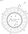
- the electric motor 10 is a three-phase AC motor having 12 poles and 18 slots. However, the number of poles, the number of slots, the number of phases, and the like can be changed as appropriate.
- the electric motor 10 can rotate at a rotation speed of 1000 rpm by applying, for example, an excitation current having an effective value of 10 A and a frequency of 100 Hz to each phase.
- the stator 20 includes an adhesively-laminated core for a stator (hereinafter, a stator core) 21 and windings (not shown).
- the stator core 21 includes an annular core back part 22 and a plurality of tooth parts 23.
- a direction of a central axis O of the stator core 21 (or the core back part 22) is referred to as the axial direction
- a radial direction (a direction orthogonal to the central axis O) of the stator core 21 (or the core back part 22) is referred to as the radial direction
- a circumferential direction a direction revolving around the central axis O of the stator core 21 (core back part 22) is referred to as the circumferential direction.
- the core back part 22 is formed in an annular shape in a plan view of the stator 20 from the axial direction.
- the plurality of tooth parts 23 extend inward in the radial direction (toward the central axis O of the core back part 22 in the radial direction) from an inner circumference of the core back part 22.
- the plurality of tooth parts 23 are disposed at equal angular intervals in the circumferential direction.
- 18 tooth parts 23 are provided at every 20 degrees with respect to a central angle centered on the central axis O.
- the plurality of tooth parts 23 are formed to have the same shape and the same size as each other. Therefore, the plurality of tooth parts 23 have the same thickness dimension as each other.
- the windings are wound around the tooth parts 23.
- the windings may be concentrated windings or distributed windings.
- the rotor 30 is disposed inside the stator 20 (stator core 21) in the radial direction.
- the rotor 30 includes a rotor core 31 and a plurality of permanent magnets 32.
- the rotor core 31 is formed in an annular shape (an annular ring shape) disposed coaxially with the stator 20.
- the rotation shaft 60 is disposed inside the rotor core 31.
- the rotation shaft 60 is fixed to the rotor core 31.
- the plurality of permanent magnets 32 are fixed to the rotor core 31.
- a set of two permanent magnets 32 form one magnetic pole.
- a plurality of sets of permanent magnets 32 are arranged at equal intervals in the circumferential direction.
- 12 sets (24 in total) of permanent magnets 32 are provided at every 30 degrees of the central angle centered on the central axis O.
- an interior permanent magnet motor is adopted as a permanent magnetic electric motor.
- a plurality of through-holes 33 that penetrate the rotor core 31 in the axial direction are formed in the rotor core 31.
- the plurality of through-holes 33 are provided to correspond to the plurality of permanent magnets 32.
- Each permanent magnet 32 is fixed to the rotor core 31 in a state in which it is disposed in the corresponding through-hole 33. Fixing of each permanent magnet 32 to the rotor core 31 can be realized, for example, by providing adhesion between an outer surface of the permanent magnet 32 and an inner surface of the through-hole 33 with an adhesive or the like.
- a surface permanent magnet motor may be adopted instead of an interior permanent magnet type.
- the stator core 21 and the rotor core 31 are both laminated cores.
- the stator core 21 is formed by laminating a plurality of electrical steel sheets 40 in the axial direction.
- a laminated thickness (the entire length along the central axis O) of each of the stator core 21 and the rotor core 31 is, for example, 50.0 mm.
- An outer diameter of the stator core 21 is, for example, 250.0 mm.
- An inner diameter of the stator core 21 is, for example, 165.0 mm.
- An outer diameter of the rotor core 31 is, for example, 163.0 mm.
- An inner diameter of the rotor core 31 is, for example, 30.0 mm.
- these values are examples, and the laminated thickness, the outer diameter, and the inner diameter of the stator core 21 and the laminated thickness, the outer diameter, and the inner diameter of the rotor core 31 are not limited to only these values.
- the inner diameter of the stator core 21 is measured with tips of the tooth parts 23 of the stator core 21 as a reference. That is, the inner diameter of the stator core 21 is a diameter of a virtual circle inscribed in the tips of all the tooth parts 23.
- Each electrical steel sheet 40 forming the stator core 21 and the rotor core 31 is formed, for example, by punching an electrical steel sheet serving as a base material, etc.
- the electrical steel sheet 40 a known electrical steel sheet can be used.
- a chemical composition of the electrical steel sheet 40 includes 2.5% to 3.9% Si, as shown below in units of mass%. By setting the chemical composition in these ranges, a yield strength YP of each electrical steel sheet 40 can be set to 380 MPa or more and 540 MPa or less.
- a non-grain-oriented electrical steel sheet is used as the electrical steel sheet 40.
- a non-grain-oriented electrical steel sheet for example, a non-grain-oriented electrical steel strip of JIS C 2552:2014 can be adopted.
- a grain-oriented electrical steel sheet may be used instead of a non-grain-oriented electrical steel sheet.
- a grain-oriented electrical steel strip of JIS C 2553:2012 can be adopted.
- Phosphate-based insulation coating are provided on both surfaces of the electrical steel sheet 40 in order to improve workability of the stator core 21 (hereinafter, may be simply referred to as a "laminated core") and an iron loss of the laminated core.
- a substance constituting the insulating coating for example, (1) an inorganic compound, (2) an organic resin, (3) a mixture of an inorganic compound and an organic resin, and the like can be adopted.
- the inorganic compound for example, (1) a complex of dichromate and boric acid, (2) a complex of phosphate and silica, and the like can be exemplified.
- the organic resin an epoxy-based resin, an acrylic-based resin, an acrylic-styrene-based resin, a polyester-based resin, a silicone-based resin, a fluorine-based resin, and the like can be exemplified.
- a lower limit of an average thickness t1 of the insulation coating is preferably 0.3 ⁇ m, more preferably to 0.7 ⁇ m.
- the insulation effect becomes saturated when the insulation coating becomes thicker. Further, as the insulation coating becomes thicker, a space factor of the electrical steel sheet 40 in the laminated core decreases, and the performance of the laminated core deteriorates. Therefore, the insulation coating may be as thin as possible within a range in which the insulation performance can be ensured.
- An upper limit of the average thickness of the insulation coating is preferably 1.2 ⁇ m, more preferably 0.9 ⁇ m.
- the average thickness t1 of the insulation coating is an average value of the entire laminated core.
- the thickness of the insulation coating is made to be almost the same over laminated positions thereof in the axial direction and a circumferential position around the central axis of the laminated core. For that reason, the average thickness t1 of the insulation coating can be set as a value measured at an upper end position of the laminated core.
- a lower limit of an average sheet thickness of the electrical steel sheet 40 is 0.15 mm, more preferably 0.18 mm in consideration of a decrease in the proportion of the electrical steel sheet 40 in the laminated core and the manufacturing costs.
- an upper limit of the average sheet thickness of the electrical steel sheet 40 is 0.35 mm, more preferably 0.30 mm.
- the average thickness of the electrical steel sheet 40 includes the thickness of the insulation coating.
- the plurality of electrical steel sheets 40 forming the stator core 21 are laminated, for example, via the adhesion parts 41 disposed in a shape of a plurality of points.
- Each of the adhesion parts 41 is formed of an adhesive that has been cured without being divided.
- a thermosetting type adhesive by polymer bonding or the like is used.
- a radical polymerization type adhesive or the like can also be used in addition to a thermosetting type adhesive, and from the viewpoint of productivity, a room temperature curing type adhesive is preferably used.
- the room temperature curing type adhesive cures at 20°C to 30°C.
- an acrylic-based adhesive is preferable.
- a typical acrylic-based adhesive includes a second generation acrylic adhesive (SGA) and the like. Any of an anaerobic adhesive, an instant adhesive, and an elastomer-containing acrylic-based adhesive can be used within the range in which the effects of the present invention are not impaired. Also, the adhesive mentioned herein is an adhesive in a state before curing and becomes the adhesion part 41 after the adhesive is cured.
- SGA second generation acrylic adhesive
- An average tensile modulus of elasticity E of the adhesion part 41 at room temperature (20°C to 30°C) is in the range of 1500 MPa to 4500 MPa. If the average tensile modulus of elasticity E of the adhesion part 41 is less than 1500 MPa, there will be a problem that rigidity of the laminated core is lowered. For that reason, a lower limit of the average tensile modulus of elasticity E of the adhesion part 41 is 1500 MPa, more preferably 1800 MPa. On the contrary, if the average tensile modulus of elasticity E of the adhesion part 41 exceeds 4500 MPa, there will be a problem that the insulation coating formed on the surface of the electrical steel sheet 40 is peeled off. For that reason, an upper limit of the average tensile modulus of elasticity E of the adhesion part 41 is 4500 MPa, more preferably 3650 MPa.
- the average tensile modulus of elasticity E is measured using a resonance method. Specifically, the tensile modulus of elasticity is measured in accordance with JIS R 1602:1995.
- a sample for measurement (not shown) is manufactured.
- This sample is obtained by providing adhesion between two electrical steel sheets 40 using an adhesive, which is a measurement target, and curing them to form the adhesion part 41.
- the adhesive is a thermosetting type
- the curing is performed by heating and pressurizing it under heating and pressurizing conditions in actual work.
- the adhesive is a room temperature curing type
- the curing is performed by pressurizing it at room temperature.
- the tensile modulus of elasticity of this sample is measured using the resonance method.
- the method for measuring the tensile modulus of elasticity using the resonance method is performed in accordance with JIS R 1602:1995. Then, the tensile modulus of elasticity of the adhesion part 41 alone can be obtained by removing an amount of influence of the electrical steel sheet 40 itself from the tensile modulus of elasticity (measured value) of the sample by calculation.
- the tensile modulus of elasticity obtained from the sample in this way is equal to an average value of the entire laminated core, this value is regarded as the average tensile modulus of elasticity E.
- the composition is set such that the average tensile modulus of elasticity E hardly changes at laminated positions in the axial direction or at circumferential positions around the central axis of the laminated core. For that reason, the average tensile modulus of elasticity E can be set to a value obtained by measuring the adhesion part 41 after curing at the upper end position of the laminated core.
- a method of providing adhesion between the plurality of electrical steel sheets 40 a method of adhering with which an adhesive is applied in a point shape to lower surfaces (surfaces on one side) of the electrical steel sheets 40, then they are overlapped, and then one or both of heating and press-stacking are performed can be adopted.
- a means in the case of heating may be any means such as a means for heating the stator core 21 in a high temperature bath or an electric furnace, or a method of directly energizing and heating the stator core 21.
- a room temperature curing type adhesive they are adhered only by press-stacking without heating.
- Fig. 3 shows an example of a formation pattern of the adhesion parts 41.
- Each adhesion part 41 is formed in a shape having a plurality of points forming a circular shape. More specifically, in the core back part 22, they are formed in point shapes having an average diameter of 12 mm at equal angular intervals in the circumferential direction thereof. Further, at a tip position of each tooth part 23, the adhesion part 41 is formed in a point shape having an average diameter of 8 mm.
- the average diameters shown here are examples and can be appropriately selected from the range of 2 mm to 20 mm.
- the formation pattern of Fig. 3 is an example, and the number and arrangements of the adhesion parts 41 can be appropriately changed as needed.
- the shape of each adhesion part 41 is not limited to a circular shape and may be a rectangular shape or another polygonal shape if necessary.
- the average thickness t2 of the adhesion part 41 is 1.0 ⁇ m or more and 3.0 ⁇ m or less.
- a lower limit of the average thickness t2 of the adhesion part 41 is 1.0 ⁇ m, more preferably 1.2 ⁇ m.
- an upper limit of the average thickness t2 of the adhesion part 41 is 3.0 ⁇ m, more preferably 2.6 ⁇ m, and most preferably 1.8 ⁇ m.
- the average thickness t2 of the adhesion part 41 is an average value of the entire laminated core.
- the average thickness t2 of the adhesion parts 41 hardly changes at laminated positions in the axial direction and the circumferential position around the central axis of the laminated core. For that reason, the average thickness t2 of the adhesion parts 41 can be set as an average value of the numerical values measured at 10 or more points in the circumferential direction at the upper end position of the laminated core.
- the average thickness t2 ( ⁇ m) of the adhesion part 41 and the average thickness t1 ( ⁇ m) of the insulation coating satisfy the following Equation 1. ⁇ 4.3 ⁇ t1 + 3.6 ⁇ t 2 ⁇ ⁇ 4.3 ⁇ t 1 + 6.9
- the average tensile modulus of elasticity E of the adhesion parts 41 is 1500 MPa to 4500 MPa, and the average tensile modulus of elasticity E (MPa) and the average thickness t1 ( ⁇ m) of the insulation coating satisfy the following Equation 2. ⁇ 5000 ⁇ t1 + 4500 ⁇ E ⁇ ⁇ 5000 ⁇ t1 + 9000
- the average thickness t2 of the adhesion parts 41 is thinner than ⁇ 4.3 ⁇ t1+3.6, the bond with the insulation coating is poor and the adhesion strength cannot be secured, and the mechanical strength of the stator core 21 cannot be maintained.
- the average thickness t2 of the adhesion parts 41 becomes thicker than -4.3 ⁇ t1 + 6.9, close adhesion between the insulation coating and the electrical steel sheet 40 tends to decrease due to the stress exerted by the adhesion parts 41 on the insulation coating. From the above, the average thickness t2 of the adhesion parts 41 is within the range of Equation 1.
- the average tensile modulus of elasticity E of the adhesion parts 41 is lower than ⁇ 5000 ⁇ t1+4500, the bond between the adhesion parts 41 and the insulation coating becomes poor and the adhesion strength cannot be maintained, and the mechanical strength of the stator core 21 may not be maintained.
- the average tensile modulus of elasticity E of the adhesion parts 41 is higher than ⁇ 5000 ⁇ t1+9000, the stress exerted by the adhesion parts 41 on the insulation coating may reduce the adhesion between the insulation coating and the electrical steel sheet 40. From the above, the average tensile modulus of elasticity E of the adhesion parts 41 is preferably within the range of Equation 2.
- the average thickness of the adhesion parts 41 can be adjusted by changing, for example, an amount of an adhesive applied.
- the average tensile modulus of elasticity E of the adhesion parts 41 can be adjusted by changing one or both of the heating and pressurizing conditions and a type of a curing agent applied at the time of adhesion.
- the average thickness t1 ( ⁇ m) and the average thickness t2 ( ⁇ m) further satisfy the following Equations 3 and 4. 0.7 ⁇ t1 ⁇ 0 .9 1.2 ⁇ t2 ⁇ 2 .6
- the plurality of electrical steel sheets forming the rotor core 31 are fixed to each other by fastening 42 (dowels) shown in Fig. 1 .
- the plurality of electrical steel sheets forming the rotor core 31 may also have a laminated structure fixed by adhesion parts similarly to the stator core 21.
- the laminated cores such as the stator core 21 and the rotor core 31 may be formed by so-called turn-stacking.
- stator core 21 was manufactured while changing various manufacturing conditions.
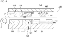
- the manufacturing device 100 While feeding electrical steel sheets P from a coil C (a hoop) in a direction of arrow F, punching is performed a plurality of times by molds disposed on each stage to gradually form shapes of the electrical steel sheets 40. Then, an adhesive is applied to lower surfaces of the electrical steel sheets 40, and the punched electrical steel sheets 40 are laminated and pressed while raising a temperature. As a result, the adhesive is cured to form the adhesion parts 41, and thus the adhesion is completed.
- the manufacturing device 100 includes a first-stage punching station 110 at a position closest to the coil C, a second-stage punching station 120 adjacently disposed on a downstream side in a conveyance direction of the electrical steel sheet P from the punching station 110, and an adhesive-coating station 130 adjacently disposed on a further downstream side thereof from the punching station 120.
- the punching station 110 includes a fixed mold 111 disposed below the electrical steel sheet P and a movable mold 112 disposed above the electrical steel sheet P.
- the punching station 120 includes a fixed mold 121 disposed below the electrical steel sheet P and a movable mold 122 disposed above the electrical steel sheet P.
- the adhesive-coating station 130 includes an applicator 131 including a plurality of injectors disposed in accordance with an adhesive coating pattern.
- the manufacturing device 100 further includes a stacking station 140 at a downstream position from the adhesive-coating station 130.
- the stacking station 140 includes a heating device 141, a fixed mold for outer shape 142, a heat insulation member 143, a movable mold for outer shape 144, and a spring 145.
- the heating device 141, the fixed mold for outer shape 142, and the heat insulation member 143 are disposed below the electrical steel sheet P.
- the movable mold for outer shape 144 and the spring 145 are disposed above the electrical steel sheet P.
- reference numeral 21 indicates the stator core.
- the electrical steel sheet P is sequentially sent out from the coil C in the direction of arrow F of Fig. 4 . Then, the electrical steel sheet P is, first, punched by the punching station 110. Subsequently, the electrical steel sheet P is punched by the punching station 120.
- the shape of the electrical steel sheet 40 having the core back part 22 and the plurality of tooth parts 23 shown in Fig. 3 is obtained on the electrical steel sheet P.
- the process proceeds to the next step in the direction of arrow F.
- the adhesive supplied from each of the injectors of the applicator 131 is applied in a point shape.
- the electrical steel sheet P is sent out to the stacking station 140, punched out by the movable mold for outer shape 144, and laminated with high accuracy.
- the electrical steel sheet 40 receives a constant pressing force by the spring 145.
- a predetermined number of electrical steel sheets 40 can be laminated. Further, the laminated core formed by stacking the electrical steel sheets 40 in this way is heated to, for example, a temperature of 200°C by the heating device 141. This heating cures the adhesives to form the adhesion parts 41.
- the stator core 21 is completed through each of the above steps.
- stator cores 21 shown in No. 1 to No. 29 in Tables 1A and 1B were manufactured.
- the chemical components of the electrical steel sheet 40 used in manufacturing each stator core 21 were unified as follows. In addition, each component value indicates mass%.
- a plurality of hoops (coils C) having the above chemical components were manufactured.
- a sheet thickness of a base steel of each hoop was unified to 0.20 mm.
- an insulation coating treatment agent containing a metal phosphate and an acrylic resin emulsion was applied to each of these hoops and baked at 300°C to form insulation coatings on both front and back surfaces thereof. At that time, thicknesses of the insulation coatings were changed for each hoop.
- each insulation coating was formed such that the average thickness t1 ( ⁇ m) on one surface becomes 0.1 ⁇ m, 0.3 ⁇ m, 0.4 ⁇ m, 0.5 ⁇ m, 0.6 ⁇ m, 0.7 ⁇ m, 0.8 ⁇ m, 0.9 ⁇ m, 1.0 ⁇ m, 1.1 ⁇ m, 1.2 ⁇ m, 1.4 ⁇ m, and 1.5 ⁇ m.
- the hoop set in the manufacturing device 100 was changed, or the type of adhesive applied to the electrical steel sheet 40, the type of curing agent added to the adhesive, the type of curing accelerator, and a coating film thickness were changed, whereby as shown in Table 1A, a plurality of laminated cores (stator cores 21) having different combinations of the average thickness t1 of the insulation coating, the type of adhesive, the average thickness t2 of the adhesion part 41, and the average tensile modulus of elasticity E were manufactured.
- a single-plate core (the electrical steel sheet 40), which has a ring shape with an outer diameter of 300 mm and an inner diameter of 240 mm and is provided with 18 rectangular tooth parts 23 having a length of 30 mm and a width of 15 mm on an inner diameter side thereof was punched out.
- the punched single-plate core was sequentially fed, it was applied with the adhesive in a point shape at each position shown in Fig. 3 , then laminated, heated while pressed at a predetermined pressure, and cured. The same work was repeated for 130 single-plate cores and one laminated core (the stator core 21) was manufactured.
- a second generation acrylic-based adhesive was used as an elastomer-based adhesive in No. 1 to No. 27 and No. 29.
- a general-purpose anaerobic adhesive was used as an anaerobic adhesive.
- the average thickness t2 of the adhesion parts 41 was adjusted by changing the coating amount for each laminated core. Also, the average tensile modulus of elasticity E of the adhesion parts 41 was adjusted for each laminated core by changing one or both of the heating and pressurizing conditions and the type of curing agent applied at the time of adhesion at the stacking station 140.
- each laminated core manufactured using the method described above was cut in a cross-section including their axes. Then, the average thickness t1 ( ⁇ m) of the insulation coatings was determined. Further, in the adhesion parts 41, the average thickness t2 ( ⁇ m) and the average tensile modulus of elasticity E after curing were determined. The average tensile modulus of elasticity E was determined using the method described above. An outer diameter of each point-shaped adhesive after curing was 5 mm on average.
- Equations 1 and 2 were substituted into the above-mentioned Equations 1 and 2 and were determined whether or not Equations 1 and 2 were satisfied.
- the results are shown in Table 1A.
- rigidity (mechanical strength) of the laminated core was also evaluated.
- the mechanical strength was evaluated with a magnitude of a load when a cutting edge with a width of 20 mm, a tip angle of 10°, and 0.15 mm R was gradually pressed against a laminated part (between a pair of electrical steel sheets 40 adjacent to each other) of the laminated core while increasing the load to generate cracks. A higher load is more preferable, and the one having 4 MPa or more was judged to be good or excellent.
- excellent indicates that high mechanical strength is secured
- "good” indicates that necessary and sufficient mechanical strength is secured
- “poor” indicates that the minimum required mechanical strength is not secured.
- the magnetic properties of the laminated core were also evaluated.
- the number of laminated sheets was set to 20
- winding was performed after covering the laminated core with insulating paper, and the core loss (W15/50 in Table 1B) was measured at a frequency of 50 Hz and a magnetic flux density of 1.5 Tesla.
- the number of lamination of the electrical steel sheets 40 when the evaluation of the magnetic properties was performed was set to 20 because almost the same results as in the case of 130 can be obtained.
- a lower core loss (W15/50 in Table 1B) is more preferable, and the one having 2.70 or less was decided to be good or excellent.
- “excellent” indicates that high magnetic properties can be secured
- “good” indicates that necessary and sufficient magnetic properties are secured
- “poor” indicates that the minimum required magnetic properties are not secured.
- Fig. 5 shows a relationship between the average thickness t1 of the insulation coatings and the average thickness t2 of the adhesion parts 41 shown in Table 1A.
- Fig. 6 shows a relationship between the average thickness t1 of the insulation coatings and the average tensile modulus of elasticity E of the adhesion parts 41 shown in Table 1A.
- the average thickness t2 of the adhesion parts 41 was thick, the proportion of the electrical steel sheets 40 in the laminated core decreased, and the magnetic properties deteriorated.
- the average thickness t2 of the adhesion parts 41 was thick, the proportion of the electrical steel sheets 40 in the laminated core decreased, and the magnetic properties deteriorated.
- the average thickness t2 of the adhesion parts 41 was thin, the adhesion strength was lowered, and the mechanical strength was lowered.
- the average thickness t2 of the adhesion parts 41 was thick, the proportion of the electrical steel sheets 40 in the laminated core decreased, and the magnetic properties deteriorated.
- the average thickness t2 of the adhesion part 41 was thin, the adhesion strength was lowered, and the mechanical strength was lowered.
- the average thickness t1 of the insulation coatings was thick, the adhesion was lowered, and the coatings were peeled off.
- the average thickness t1 of the insulation coatings was thick, the adhesion was lowered, and the coatings were peeled off.
- the adhesive used for adhesion was an anaerobic adhesive and did not have a sea-island structure, and thus the cured adhesion parts 41 generated strain in the electrical steel sheets 40, and due to the strain of the electrical steel sheets 40, the magnetic properties deteriorated.
- the average thickness t1 of the insulation coatings also satisfies the range of 0.7 ⁇ m to 0.9 ⁇ m. For that reason, optimization has been performed with respect to securing of insulation performance is deterioration of performance as a laminated core, which is the most preferable among all the examples.
- thermosetting type adhesive was applied, but there is no difference in the basic tendency even with a room temperature curing type adhesive.
- the shape of the stator core 21 is not limited to the form shown in the above embodiment. Specifically, dimensions of the outer diameter and the inner diameter of the stator core 21, the laminated thickness, the number of slots, a dimensional ratio of the tooth part 23 between in the circumferential direction and in the radial direction, a dimensional ratio in the radial direction between the tooth part 23 and the core back part 22, and the like can be arbitrarily designed in accordance with desired properties of the electric motor.
- the set of two permanent magnets 32 form one magnetic pole, but the present invention is not limited thereto.
- one permanent magnet 32 may form one magnetic pole, or three or more permanent magnets 32 may form one magnetic pole.
- the permanent magnetic electric motor has been described as an example of the electric motor 10, but as illustrated below, the structure of the electric motor 10 is not limited thereto, and various known structures not illustrated below can also be adopted.
- the permanent magnetic electric motor has been described as an example of the electric motor 10, but the present invention is not limited thereto.
- the electric motor 10 may be a reluctance motor or an electromagnet field motor (a wound-field motor).
- the synchronous motor has been described as an example of the AC motor, but the present invention is not limited thereto.
- the electric motor 10 may be an induction motor.
- the AC motor has been described as an example of the electric motor 10, but the present invention is not limited thereto.
- the electric motor 10 may be a DC motor.
- the motor has been described as an example of the electric motor 10, but the present invention is not limited thereto.
- the electric motor 10 may be a generator.
- an adhesively-laminated core for a stator that can both prevent peeling of an insulation coating and inhibit deterioration of magnetic properties due to a stress applied to an electrical steel sheet by an adhesion part, and an electric motor including the adhesively-laminated core for the stator can be provided. Therefore, it provides great industrial applicability.
Landscapes
- Engineering & Computer Science (AREA)
- Power Engineering (AREA)
- Manufacturing & Machinery (AREA)
- Chemical & Material Sciences (AREA)
- Organic Chemistry (AREA)
- Iron Core Of Rotating Electric Machines (AREA)
- Manufacture Of Motors, Generators (AREA)
Priority Applications (1)
| Application Number | Priority Date | Filing Date | Title |
|---|---|---|---|
| RS20250894A RS67189B1 (sr) | 2018-12-17 | 2019-12-17 | Lepljeno laminirano jezgro za stator i električni motor |
Applications Claiming Priority (2)
| Application Number | Priority Date | Filing Date | Title |
|---|---|---|---|
| JP2018235864 | 2018-12-17 | ||
| PCT/JP2019/049266 WO2020129925A1 (ja) | 2018-12-17 | 2019-12-17 | ステータ用接着積層コアおよび回転電機 |
Publications (3)
| Publication Number | Publication Date |
|---|---|
| EP3902121A1 true EP3902121A1 (de) | 2021-10-27 |
| EP3902121A4 EP3902121A4 (de) | 2022-11-30 |
| EP3902121B1 EP3902121B1 (de) | 2025-08-13 |
Family
ID=71101789
Family Applications (1)
| Application Number | Title | Priority Date | Filing Date |
|---|---|---|---|
| EP19899295.0A Active EP3902121B1 (de) | 2018-12-17 | 2019-12-17 | Adhäsiv laminierter kern für stator und elektromotor |
Country Status (12)
| Country | Link |
|---|---|
| US (1) | US12154711B2 (de) |
| EP (1) | EP3902121B1 (de) |
| JP (2) | JP7486434B2 (de) |
| KR (1) | KR102607691B1 (de) |
| CN (1) | CN113169639B (de) |
| EA (1) | EA202192059A1 (de) |
| MY (1) | MY208350A (de) |
| PL (1) | PL3902121T3 (de) |
| RS (1) | RS67189B1 (de) |
| SG (1) | SG11202108888RA (de) |
| TW (1) | TWI717940B (de) |
| WO (1) | WO2020129925A1 (de) |
Families Citing this family (17)
| Publication number | Priority date | Publication date | Assignee | Title |
|---|---|---|---|---|
| CN113169594B (zh) | 2018-12-17 | 2025-08-12 | 日本制铁株式会社 | 层叠铁芯以及旋转电机 |
| CA3131673C (en) | 2018-12-17 | 2024-02-20 | Nippon Steel Corporation | Laminated core, method of manufacturing same, and electric motor |
| MY207178A (en) | 2018-12-17 | 2025-02-04 | Nippon Steel Corp | Laminated core and electric motor |
| RS67409B1 (sr) | 2018-12-17 | 2025-12-31 | Nippon Steel Corp | Lepljivo laminirano jezgro za stator i električni motor |
| EP3902120A4 (de) | 2018-12-17 | 2022-10-05 | Nippon Steel Corporation | Gestapelter kern und rotierende elektrische maschine |
| US11990795B2 (en) | 2018-12-17 | 2024-05-21 | Nippon Steel Corporation | Adhesively-laminated core for stator, method of manufacturing same, and electric motor |
| EA202192072A1 (ru) | 2018-12-17 | 2021-11-09 | Ниппон Стил Корпорейшн | Шихтованный сердечник и электродвигатель |
| EP3902123B1 (de) | 2018-12-17 | 2025-10-29 | Nippon Steel Corporation | Laminierter kern, verfahren zur herstellung des laminierten kerns und elektromotor |
| WO2020129937A1 (ja) | 2018-12-17 | 2020-06-25 | 日本製鉄株式会社 | 積層コアおよび回転電機 |
| MY204004A (en) | 2018-12-17 | 2024-07-31 | Nippon Steel Corp | Adhesively-laminated core, manufacturing method thereof, and electric motor |
| EP3902104A4 (de) | 2018-12-17 | 2022-10-05 | Nippon Steel Corporation | Laminierter kern und rotierende elektrische maschine |
| PL3902105T3 (pl) | 2018-12-17 | 2024-12-02 | Nippon Steel Corporation | Laminowany rdzeń oraz wirująca maszyna elektryczna |
| TWI744743B (zh) | 2018-12-17 | 2021-11-01 | 日商日本製鐵股份有限公司 | 積層鐵芯及旋轉電機 |
| EP3902109A4 (de) | 2018-12-17 | 2022-10-05 | Nippon Steel Corporation | Laminierter kern und rotierende maschine |
| JP7515403B2 (ja) | 2018-12-17 | 2024-07-12 | 日本製鉄株式会社 | ステータ用接着積層コア、その製造方法、および回転電機 |
| CA3131358A1 (en) | 2018-12-17 | 2020-06-25 | Nippon Steel Corporation | Laminated core, core block, electric motor and method of producing core block |
| TWI837708B (zh) * | 2022-06-20 | 2024-04-01 | 大銀微系統股份有限公司 | 馬達轉子鐵芯構造 |
Family Cites Families (194)
| Publication number | Priority date | Publication date | Assignee | Title |
|---|---|---|---|---|
| US3386058A (en) | 1966-11-21 | 1968-05-28 | Westinghouse Electric Corp | Inductive assembly with supporting means |
| US4025379A (en) | 1973-05-03 | 1977-05-24 | Whetstone Clayton N | Method of making laminated magnetic material |
| US4103195A (en) | 1976-08-11 | 1978-07-25 | General Electric Company | Bonded laminations forming a stator core |
| JPS5665326A (en) | 1979-10-29 | 1981-06-03 | Tdk Corp | Magnetic core for magnetic head |
| JPS576427A (en) | 1980-06-11 | 1982-01-13 | Canon Inc | Manufacture of magnetic core |
| US4413406A (en) | 1981-03-19 | 1983-11-08 | General Electric Company | Processing amorphous metal into packets by bonding with low melting point material |
| JPS60170681A (ja) | 1984-02-16 | 1985-09-04 | Nippon Synthetic Chem Ind Co Ltd:The | 接着剤組成物 |
| JPS60186834A (ja) | 1984-03-07 | 1985-09-24 | Toray Ind Inc | 水現像可能な感光性樹脂版材 |
| JPS60186834U (ja) | 1984-05-18 | 1985-12-11 | 株式会社東芝 | 回転電機の固定子鉄心 |
| JPS629951A (ja) | 1985-07-08 | 1987-01-17 | 新日本製鐵株式会社 | 成形性に優れたラミネ−ト鋼板 |
| JPS63207639A (ja) | 1987-02-25 | 1988-08-29 | 日新製鋼株式会社 | 制振鋼板及びその製造方法 |
| JPH01168777A (ja) * | 1987-12-25 | 1989-07-04 | Konishi Kk | 接着剤組成物 |
| JPH03124247A (ja) | 1989-10-05 | 1991-05-27 | Aichi Emerson Electric Co Ltd | 回転電機の固定子 |
| JPH03247683A (ja) | 1990-02-23 | 1991-11-05 | Sumitomo Chem Co Ltd | アクリル系接着剤組成物 |
| JPH0428743U (de) | 1990-05-22 | 1992-03-06 | ||
| JP2897344B2 (ja) | 1990-05-23 | 1999-05-31 | 住友化学工業株式会社 | 熱可塑性樹脂組成物 |
| JPH08996B2 (ja) | 1991-01-24 | 1996-01-10 | 新日本製鐵株式会社 | 溶接性、塗料密着性に優れた表面処理鋼板の製造方法 |
| US5448119A (en) | 1991-03-29 | 1995-09-05 | Nagano Nidec Corporation | Spindle motor |
| US5142178A (en) | 1991-04-12 | 1992-08-25 | Emerson Electric Co. | Apparatus for aligning stacked laminations of a dynamoelectric machine |
| JPH0614481A (ja) | 1992-06-25 | 1994-01-21 | Mitsubishi Electric Corp | 電機子鉄心 |
| JPH07118620A (ja) | 1993-10-22 | 1995-05-09 | Nippon Zeon Co Ltd | エポキシ系接着剤組成物 |
| JPH07298567A (ja) | 1994-04-26 | 1995-11-10 | Honda Motor Co Ltd | 積層鋼板の接着用加熱装置 |
| JPH08259899A (ja) | 1995-03-23 | 1996-10-08 | Three Bond Co Ltd | シアノアクリレート系接着剤組成物 |
| JP3266448B2 (ja) * | 1995-03-27 | 2002-03-18 | 株式会社リコー | ブラシレスモータの回転体装置 |
| JPH10304610A (ja) | 1997-04-22 | 1998-11-13 | Toshiba Corp | 永久磁石回転子及び永久磁石回転子用抜き板の製造方法 |
| JP3369941B2 (ja) | 1997-11-27 | 2003-01-20 | 日本鋼管株式会社 | 接着強度、耐食性及び耐ブロッキング性に優れた接着鉄芯用電磁鋼板の製造方法 |
| JP2000050539A (ja) | 1998-07-28 | 2000-02-18 | Toshiba Corp | 回転電機の固定子鉄心、固定子鉄心用鋼板部品、固定子鉄心の製造方法および固定子鉄心用鋼板部品の製造方法 |
| JP2000152570A (ja) | 1998-11-06 | 2000-05-30 | Toshiba Corp | 磁石鉄心の製造方法 |
| JP2001115125A (ja) | 1999-10-01 | 2001-04-24 | Three M Innovative Properties Co | ネオジム磁石用接着剤及びモータ |
| FR2803126B1 (fr) | 1999-12-23 | 2006-04-14 | Valeo Equip Electr Moteur | Alternateur pour vehicule a stator generant peu de bruit magnetique |
| JP2001251828A (ja) | 2000-03-02 | 2001-09-14 | Moric Co Ltd | 内燃機関用多極磁石式発電機 |
| JP2002078257A (ja) | 2000-08-24 | 2002-03-15 | Mitsubishi Electric Corp | モーター及びそのローター |
| JP4665298B2 (ja) * | 2000-08-25 | 2011-04-06 | 東レ株式会社 | 半導体装置用接着剤付きテープおよびそれを用いた銅張り積層板、半導体接続用基板ならびに半導体装置 |
| JP3730218B2 (ja) | 2000-08-29 | 2005-12-21 | 三菱電機株式会社 | 積重ステータコアとその製造方法および回転電動機とその製造方法 |
| JP2002164224A (ja) | 2000-08-30 | 2002-06-07 | Mitsui Chemicals Inc | 磁性基材およびその製造方法 |
| JP4020236B2 (ja) | 2000-09-18 | 2007-12-12 | 電気化学工業株式会社 | 硬化性樹脂組成物、硬化体、接着剤組成物及び接合体 |
| JP2002105283A (ja) | 2000-09-28 | 2002-04-10 | Nhk Spring Co Ltd | エポキシ樹脂分散体およびそれを用いた銅張り積層板及び銅張り金属基板 |
| JP2002125341A (ja) | 2000-10-16 | 2002-04-26 | Denki Kagaku Kogyo Kk | ステーター及びそれを用いたモーター |
| JP2002151335A (ja) | 2000-11-10 | 2002-05-24 | Nippon Steel Corp | 鉄損特性の優れた積層鉄芯およびその製造方法 |
| JP3725776B2 (ja) | 2000-11-10 | 2005-12-14 | 新日本製鐵株式会社 | 積層鉄芯の製造方法およびその製造装置 |
| EP1241773B1 (de) | 2001-03-14 | 2012-09-12 | Nissan Motor Co., Ltd. | Drehende elektrische Maschine mit Spalttopf |
| JP4076323B2 (ja) * | 2001-05-08 | 2008-04-16 | 電気化学工業株式会社 | 硬化性樹脂組成物、硬化体、接着剤組成物及び接合体 |
| JP4018885B2 (ja) | 2001-05-25 | 2007-12-05 | 株式会社三井ハイテック | 積層鉄心 |
| KR100526286B1 (ko) * | 2001-08-17 | 2005-11-08 | 제이에프이 스틸 가부시키가이샤 | 적층 철심의 제조장치 및 제조방법 |
| JP3594003B2 (ja) | 2001-08-28 | 2004-11-24 | 日産自動車株式会社 | 回転電機及びその製造方法 |
| JP2003199303A (ja) * | 2001-12-27 | 2003-07-11 | Matsushita Electric Ind Co Ltd | モータの製造方法 |
| JP4165072B2 (ja) | 2002-01-15 | 2008-10-15 | 日立化成工業株式会社 | 接着剤組成物、接着フィルム、半導体搭載用配線基板及び半導体装置とその製造方法 |
| JP2003219585A (ja) | 2002-01-22 | 2003-07-31 | Mitsubishi Electric Corp | 積層鉄心およびその製造方法 |
| JP3771933B2 (ja) | 2002-03-08 | 2006-05-10 | Jfeスチール株式会社 | 積層コア用材料及びその製造方法 |
| JP2003284274A (ja) | 2002-03-22 | 2003-10-03 | Nippon Steel Corp | 永久磁石同期モータのロータ |
| JP2004088970A (ja) * | 2002-08-29 | 2004-03-18 | Hitachi Ltd | 積層鉄心とそれを用いた回転電機およびトランス |
| JP2004111509A (ja) | 2002-09-17 | 2004-04-08 | Nippon Steel Corp | 鉄損特性の優れた積層鉄芯及びその製造方法 |
| JP4222000B2 (ja) | 2002-10-29 | 2009-02-12 | Nok株式会社 | 磁気エンコーダ |
| JP3791492B2 (ja) | 2002-12-25 | 2006-06-28 | 株式会社日立製作所 | 回転電機及び電動車両並びに樹脂のインサート成形方法 |
| JP4143090B2 (ja) | 2003-02-03 | 2008-09-03 | 新日本製鐵株式会社 | 接着用表面被覆電磁鋼板 |
| JP4987216B2 (ja) | 2003-06-25 | 2012-07-25 | Jfeスチール株式会社 | 寸法精度に優れた積層コア及びその製造方法 |
| US7362031B2 (en) | 2003-09-03 | 2008-04-22 | Mitsuba Corporation | Electric motor |
| JP2005269732A (ja) | 2004-03-17 | 2005-09-29 | Nippon Steel Corp | 鉄芯の製造方法とその方法に適した装置 |
| JP2005268589A (ja) | 2004-03-19 | 2005-09-29 | Nippon Steel Corp | エネルギー変換機器用磁性部材の簡易製造方法 |
| JP4548049B2 (ja) | 2004-09-01 | 2010-09-22 | 株式会社日立製作所 | 回転電機 |
| JP4498154B2 (ja) | 2005-01-27 | 2010-07-07 | ファナック株式会社 | モータの製造方法、及びモータ製造装置 |
| JP2006254530A (ja) | 2005-03-08 | 2006-09-21 | Mitsubishi Electric Corp | 電動機 |
| JP2006288114A (ja) | 2005-04-01 | 2006-10-19 | Mitsui High Tec Inc | 積層鉄心、及び積層鉄心の製造方法 |
| JP2006353001A (ja) | 2005-06-15 | 2006-12-28 | Japan Servo Co Ltd | 積層鉄心とその製造方法及び製造装置 |
| JP4687289B2 (ja) | 2005-07-08 | 2011-05-25 | 東洋紡績株式会社 | ポリアミド系混合樹脂積層フィルムロール、およびその製造方法 |
| JP4586669B2 (ja) | 2005-08-01 | 2010-11-24 | 住友金属工業株式会社 | 回転子用無方向性電磁鋼板の製造方法 |
| JP2007053896A (ja) | 2005-08-17 | 2007-03-01 | Minebea Co Ltd | ステータユニット及びその製造方法 |
| JP4236056B2 (ja) | 2006-02-08 | 2009-03-11 | 三菱電機株式会社 | 磁石発電機 |
| KR100808194B1 (ko) | 2006-05-19 | 2008-02-29 | 엘지전자 주식회사 | 아우터 로터 타입 모터의 스테이터 |
| JP5309431B2 (ja) * | 2006-08-04 | 2013-10-09 | 新日鐵住金株式会社 | 鋼板剪断面の鋼板間抵抗が高い電磁鋼の積層鋼板およびそのカシメ方法 |
| JP4938389B2 (ja) | 2006-09-06 | 2012-05-23 | 三菱電機株式会社 | 積層コアおよびステータ |
| WO2008044740A1 (en) | 2006-10-13 | 2008-04-17 | Mitsui High-Tec, Inc. | Laminated iron core, and its manufacturing method |
| EP2115086A1 (de) | 2007-02-06 | 2009-11-11 | Siemens Transformers Austria GmbH & Co. KG | Isoliermaterial für elektrische maschinen |
| ITMI20070508A1 (it) | 2007-03-14 | 2008-09-15 | Corrada Spa | Articolo laminare per uso elettrico procedimento e macchine per realizzare detto articolo laminare |
| JP5129810B2 (ja) | 2007-05-09 | 2013-01-30 | 株式会社三井ハイテック | 積層鉄心及びその製造方法 |
| KR100988184B1 (ko) | 2007-07-19 | 2010-10-18 | 세키스이가가쿠 고교가부시키가이샤 | 전자 부품용 접착제 |
| JP2009072035A (ja) | 2007-09-18 | 2009-04-02 | Meidensha Corp | 回転電機の回転子コア |
| JP5211651B2 (ja) | 2007-11-15 | 2013-06-12 | パナソニック株式会社 | モータおよびそれを用いた電子機器 |
| JP5172367B2 (ja) | 2008-01-23 | 2013-03-27 | 三菱電機株式会社 | 積層コア、積層コアの製造方法、積層コアの製造装置およびステータ |
| WO2009101961A1 (ja) | 2008-02-15 | 2009-08-20 | Kuraray Co., Ltd. | 硬化性樹脂組成物および樹脂硬化物 |
| JP5428218B2 (ja) | 2008-06-23 | 2014-02-26 | 富士電機株式会社 | 永久磁石形回転電機の回転子構造 |
| JP2010081659A (ja) | 2008-09-24 | 2010-04-08 | Hitachi Ltd | 電動機及びそれを用いた電動圧縮機 |
| JP5701613B2 (ja) | 2009-01-15 | 2015-04-15 | 株式会社カネカ | 硬化性組成物、その硬化物、及びその製造方法 |
| JP5084770B2 (ja) | 2009-03-13 | 2012-11-28 | 三菱電機株式会社 | 電動機及び圧縮機及び空気調和機 |
| WO2010109272A2 (de) | 2009-03-26 | 2010-09-30 | Vacuumschmelze Gmbh & Co. Kg | Blechpaket mit weichmagnetischem werkstoff und verfahren zum stoffschlüssigen fügen von paketlamellen zu einem weichmagnetischen blechpaket |
| JP2010239691A (ja) | 2009-03-30 | 2010-10-21 | Denso Corp | 回転電機の固定子及び回転電機 |
| JP5444812B2 (ja) | 2009-04-22 | 2014-03-19 | Jfeスチール株式会社 | 高速モータ用コア材料 |
| CN102459696B (zh) | 2009-06-17 | 2013-10-16 | 新日铁住金株式会社 | 具有绝缘覆盖膜的电磁钢板及其制造方法 |
| JP2011023523A (ja) * | 2009-07-15 | 2011-02-03 | Nippon Steel Corp | 良好な熱伝導性を有する電磁鋼板積層コアおよびその製造方法 |
| CN102470627B (zh) | 2009-07-31 | 2014-09-10 | 新日铁住金株式会社 | 层叠钢板 |
| BE1019128A3 (nl) | 2009-11-06 | 2012-03-06 | Atlas Copco Airpower Nv | Gelamelleerde kern van een magneetlager en werkwijze voor het vervaardigen van zulke gelamelleerde kern. |
| JPWO2011077830A1 (ja) * | 2009-12-24 | 2013-05-02 | 株式会社安川電機 | 積層コア、この積層コアを備えた電動機および積層コアの製造方法 |
| JP5716339B2 (ja) | 2010-01-08 | 2015-05-13 | 大日本印刷株式会社 | 粘接着シートおよびそれを用いた接着方法 |
| JP5423465B2 (ja) | 2010-02-18 | 2014-02-19 | 新日鐵住金株式会社 | 電磁鋼板および電磁鋼板の製造方法 |
| JP5844963B2 (ja) | 2010-03-19 | 2016-01-20 | 積水化学工業株式会社 | 電子部品用接着剤 |
| JP5459110B2 (ja) | 2010-06-30 | 2014-04-02 | 株式会社デンソー | 回転電機の固定子 |
| JP2012029494A (ja) | 2010-07-26 | 2012-02-09 | Nissan Motor Co Ltd | 電動機およびその製造方法 |
| CN203368163U (zh) * | 2010-08-26 | 2013-12-25 | 三菱电机株式会社 | 旋转电机和用于制造其定子铁芯的定子铁芯制造装置 |
| JP5350342B2 (ja) | 2010-09-08 | 2013-11-27 | 三菱電機株式会社 | 同期電動機の回転子 |
| JP2012061820A (ja) | 2010-09-17 | 2012-03-29 | Dainippon Printing Co Ltd | 繊維強化複合材料の賦型方法 |
| JP2012120299A (ja) | 2010-11-30 | 2012-06-21 | Mitsubishi Electric Corp | ステータコア、回転電機およびステータコアの製造方法 |
| JP5809819B2 (ja) | 2011-03-18 | 2015-11-11 | 富士重工業株式会社 | 回転電機 |
| JP5915075B2 (ja) | 2011-10-21 | 2016-05-11 | Jfeスチール株式会社 | 積層コアの製造方法 |
| CN104144797B (zh) | 2012-02-29 | 2016-06-22 | 株式会社普利司通 | 轮胎 |
| JP5966445B2 (ja) | 2012-03-01 | 2016-08-10 | 住友ベークライト株式会社 | 固定用樹脂組成物、ロータ、および自動車 |
| IN2014DN07130A (de) | 2012-03-01 | 2015-04-24 | Sumitomo Bakelite Co | |
| DE102012005795A1 (de) | 2012-03-14 | 2013-09-19 | Kienle + Spiess Gmbh | Lamellenpaket und Verfahren zu seiner Herstellung |
| JP2013194130A (ja) | 2012-03-19 | 2013-09-30 | Nitto Denko Corp | 塗膜保護シート |
| JP2013253153A (ja) | 2012-06-06 | 2013-12-19 | Mitsubishi Chemicals Corp | エポキシ樹脂、エポキシ樹脂組成物、硬化物及び光学部材 |
| JP2014014231A (ja) | 2012-07-04 | 2014-01-23 | Mitsubishi Heavy Ind Ltd | 電動モータ |
| JP2014019777A (ja) | 2012-07-18 | 2014-02-03 | Nitto Denko Corp | 表面保護シート |
| JP6134497B2 (ja) * | 2012-11-08 | 2017-05-24 | 京セラ株式会社 | 積層コアの製造方法 |
| WO2014102915A1 (ja) | 2012-12-26 | 2014-07-03 | 株式会社 日立製作所 | 低融点ガラス樹脂複合材料と、それを用いた電子・電気機器 |
| JP5896937B2 (ja) | 2013-02-08 | 2016-03-30 | 三菱電機株式会社 | 分割鉄心、及びこの分割鉄心を用いた固定子、並びにこの固定子を備えた回転電機 |
| JP2015012756A (ja) * | 2013-07-01 | 2015-01-19 | 日本精工株式会社 | ダイレクトドライブモータ |
| US9490667B2 (en) | 2013-07-23 | 2016-11-08 | General Electric Company | Apparatus and system for attaching integral spacers to laminations |
| KR101539849B1 (ko) | 2013-09-23 | 2015-07-28 | 뉴모텍(주) | 절연 코팅에 적합한 구조를 갖는 모터의 적층 코어 |
| JP6164039B2 (ja) | 2013-10-21 | 2017-07-19 | アイシン・エィ・ダブリュ株式会社 | 積層鉄心の製造方法 |
| JP6066936B2 (ja) | 2014-01-17 | 2017-01-25 | 三菱電機株式会社 | 積層鉄心の製造方法、固定子の製造方法 |
| JP6064923B2 (ja) | 2014-01-29 | 2017-01-25 | Jfeスチール株式会社 | 積層鉄心の製造方法 |
| JP6065032B2 (ja) | 2014-01-29 | 2017-01-25 | Jfeスチール株式会社 | 積層鉄心製造方法および積層鉄心 |
| JP6248711B2 (ja) | 2014-03-06 | 2017-12-20 | 株式会社デンソー | 回転電機の固定子 |
| JP6383202B2 (ja) | 2014-07-24 | 2018-08-29 | 株式会社三井ハイテック | 積層鉄心の製造方法及び積層鉄心 |
| EP3176285B1 (de) | 2014-07-29 | 2018-09-05 | JFE Steel Corporation | Elektrostahlblech zum stapeln, gestapeltes elektrostahlblech, verfahren zur herstellung eines gestapelten elektrostahlblechs und eisenkern für kraftfahrzeugmotor |
| JP6431316B2 (ja) | 2014-08-26 | 2018-11-28 | 日東シンコー株式会社 | モーター用絶縁シート |
| JP6479392B2 (ja) | 2014-09-30 | 2019-03-06 | 株式会社三井ハイテック | 積層鉄心及びその製造方法 |
| JP6303978B2 (ja) | 2014-10-27 | 2018-04-04 | トヨタ自動車株式会社 | 回転電機のステータ |
| CN104454852B (zh) * | 2014-11-28 | 2016-05-18 | 烟台首钢磁性材料股份有限公司 | 一种永磁钕铁硼磁钢绝缘粘接的方法及专用挤压工装 |
| JP6247630B2 (ja) | 2014-12-11 | 2017-12-13 | Ckd株式会社 | コイルの冷却構造 |
| JP6587800B2 (ja) | 2014-12-26 | 2019-10-09 | Jfeスチール株式会社 | 積層鉄心の製造方法 |
| JP6210058B2 (ja) | 2014-12-26 | 2017-10-11 | Jfeスチール株式会社 | 積層鉄心用の打抜き加工方法及び積層鉄心の製造方法 |
| WO2016113876A1 (ja) | 2015-01-15 | 2016-07-21 | 三菱電機株式会社 | 回転電機 |
| JP2016140134A (ja) | 2015-01-26 | 2016-08-04 | アイシン・エィ・ダブリュ株式会社 | モータコアおよびモータコアの製造方法 |
| CN107210112B (zh) * | 2015-01-30 | 2018-12-18 | 三菱电机株式会社 | 磁铁粘接体 |
| JP6249417B2 (ja) | 2015-03-09 | 2017-12-20 | 三菱電機株式会社 | 回転電機および電動パワーステアリング装置 |
| JP6432397B2 (ja) | 2015-03-12 | 2018-12-05 | アイシン・エィ・ダブリュ株式会社 | モータの製造方法およびモータコア |
| CN108410376B (zh) | 2015-04-10 | 2022-03-18 | 株式会社寺冈制作所 | 粘接片 |
| JP6495092B2 (ja) | 2015-05-07 | 2019-04-03 | 株式会社三井ハイテック | 分割型積層鉄心及びその製造方法 |
| DE102016109768A1 (de) | 2015-05-27 | 2016-12-01 | Johnson Electric S.A. | Magnetkern für einen Elektromotor |
| JP2016226170A (ja) | 2015-05-29 | 2016-12-28 | トヨタ自動車株式会社 | 電動機用積層コア |
| JP6627270B2 (ja) | 2015-06-12 | 2020-01-08 | 住友ベークライト株式会社 | 整流子 |
| JP2017011863A (ja) * | 2015-06-22 | 2017-01-12 | 新日鐵住金株式会社 | モータ鉄心用積層電磁鋼板およびその製造方法 |
| JP2017028911A (ja) | 2015-07-24 | 2017-02-02 | 日東シンコー株式会社 | 回転電機用絶縁紙 |
| WO2017033229A1 (ja) | 2015-08-21 | 2017-03-02 | 三菱電機株式会社 | 永久磁石埋込型モータ、圧縮機、および冷凍空調装置 |
| JPWO2017033873A1 (ja) * | 2015-08-21 | 2018-08-09 | 吉川工業株式会社 | ステータコア及びそれを備えたモータ |
| JP6429129B2 (ja) | 2015-08-26 | 2018-11-28 | 日産自動車株式会社 | ロータの製造方法 |
| JP6191801B1 (ja) | 2015-10-07 | 2017-09-06 | 大日本印刷株式会社 | 接着シートセットおよび物品の製造方法 |
| JP6560588B2 (ja) | 2015-10-08 | 2019-08-14 | 住友電気工業株式会社 | 誘導加熱装置、及び発電システム |
| JP2017075279A (ja) | 2015-10-16 | 2017-04-20 | 株式会社菱晃 | 接着剤及び接合体 |
| WO2017090137A1 (ja) | 2015-11-25 | 2017-06-01 | 三菱電機株式会社 | 回転電機および回転電機の製造方法 |
| WO2017090571A1 (ja) | 2015-11-27 | 2017-06-01 | 日本電産株式会社 | モータおよびモータの製造方法 |
| WO2017104479A1 (ja) | 2015-12-18 | 2017-06-22 | Dic株式会社 | 熱硬化性接着シート、補強部付フレキシブルプリント配線板、その製造方法及び電子機器 |
| KR102108990B1 (ko) | 2016-02-25 | 2020-05-11 | 히타치가세이가부시끼가이샤 | 에폭시 수지 조성물, 반경화 에폭시 수지 조성물, 경화 에폭시 수지 조성물, 성형물 및 성형 경화물 |
| WO2017170957A1 (ja) | 2016-03-31 | 2017-10-05 | デンカ株式会社 | 組成物 |
| CN109155574B (zh) | 2016-05-20 | 2020-11-06 | 日本电产株式会社 | 定子铁芯的制造方法 |
| JP6874550B2 (ja) | 2016-08-01 | 2021-05-19 | 株式会社リコー | インク、インク容器、画像形成方法、画像形成装置、画像形成物、及び液体吐出装置 |
| CN107674499B (zh) | 2016-08-01 | 2021-07-13 | 株式会社理光 | 墨水,墨水容器,液体排出装置,图像形成方法及其装置 |
| JP6376706B2 (ja) | 2016-08-29 | 2018-08-22 | 本田技研工業株式会社 | 積層鋼板の製造方法および製造装置 |
| WO2018043429A1 (ja) | 2016-09-01 | 2018-03-08 | 三菱電機株式会社 | 積層鉄心、積層鉄心の製造方法、および積層鉄心を用いた電機子 |
| JP6848314B2 (ja) | 2016-10-03 | 2021-03-24 | 日本製鉄株式会社 | ステータコアおよび回転電機 |
| JP6724735B2 (ja) | 2016-11-08 | 2020-07-15 | トヨタ自動車株式会社 | 回転電機のステータ |
| KR101874918B1 (ko) | 2016-11-15 | 2018-07-06 | 지에스칼텍스 주식회사 | 저비중 폴리프로필렌 수지 조성물 및 이를 이용한 자동차 내장재용 성형품 |
| JP6905905B2 (ja) | 2016-12-06 | 2021-07-21 | パナソニック株式会社 | 鉄心およびモータ |
| CN108155730B (zh) | 2016-12-06 | 2022-02-25 | 松下电器产业株式会社 | 铁芯和电机 |
| JP6490313B2 (ja) | 2016-12-07 | 2019-03-27 | パナソニック株式会社 | 鉄心及びモータ |
| JP6543608B2 (ja) | 2016-12-22 | 2019-07-10 | 株式会社三井ハイテック | 積層鉄心の製造方法及び積層鉄心の製造装置 |
| WO2018138864A1 (ja) | 2017-01-27 | 2018-08-02 | 三菱電機株式会社 | 固定子、電動機、圧縮機、および冷凍空調装置 |
| FR3062970B1 (fr) | 2017-02-13 | 2021-07-23 | Valeo Equip Electr Moteur | Stator de machine electrique tournante |
| JP2018138634A (ja) | 2017-02-24 | 2018-09-06 | 三菱ケミカル株式会社 | 樹脂組成物および該樹脂組成物を用いた半導体装置 |
| JP6866696B2 (ja) * | 2017-03-07 | 2021-04-28 | 日本製鉄株式会社 | 無方向性電磁鋼板およびその製造方法、並びにモータコアおよびその製造方法 |
| CN110546224B (zh) | 2017-04-26 | 2022-04-19 | 东亚合成株式会社 | 粘接剂组合物 |
| CN110622393B (zh) | 2017-05-10 | 2022-05-13 | 三菱电机株式会社 | 定子、电动机、压缩机、制冷空调装置及定子的制造方法 |
| CN110637408B (zh) | 2017-05-23 | 2022-11-15 | 三键有限公司 | 层叠钢板及制造方法、发动机及层叠钢板用胶粘剂组合物 |
| JP2018201303A (ja) | 2017-05-29 | 2018-12-20 | 日本電産株式会社 | モータ |
| US11616407B2 (en) | 2017-08-25 | 2023-03-28 | Mitsubishi Electric Corporation | Segment-core coupled body and method of manufacturing armature |
| DE102017010685A1 (de) | 2017-11-16 | 2019-05-16 | Wieland-Werke Ag | Kurzschlussläufer und Verfahren zur Herstellung eines Kurzschlussläufers |
| JP6826566B2 (ja) | 2018-08-06 | 2021-02-03 | 本田技研工業株式会社 | 回転電機用ステータコアおよび回転電機 |
| EA202192072A1 (ru) | 2018-12-17 | 2021-11-09 | Ниппон Стил Корпорейшн | Шихтованный сердечник и электродвигатель |
| TWI744743B (zh) | 2018-12-17 | 2021-11-01 | 日商日本製鐵股份有限公司 | 積層鐵芯及旋轉電機 |
| MY204004A (en) | 2018-12-17 | 2024-07-31 | Nippon Steel Corp | Adhesively-laminated core, manufacturing method thereof, and electric motor |
| EP3902123B1 (de) | 2018-12-17 | 2025-10-29 | Nippon Steel Corporation | Laminierter kern, verfahren zur herstellung des laminierten kerns und elektromotor |
| US11990795B2 (en) | 2018-12-17 | 2024-05-21 | Nippon Steel Corporation | Adhesively-laminated core for stator, method of manufacturing same, and electric motor |
| WO2020129937A1 (ja) | 2018-12-17 | 2020-06-25 | 日本製鉄株式会社 | 積層コアおよび回転電機 |
| RS67409B1 (sr) | 2018-12-17 | 2025-12-31 | Nippon Steel Corp | Lepljivo laminirano jezgro za stator i električni motor |
| PL3902105T3 (pl) | 2018-12-17 | 2024-12-02 | Nippon Steel Corporation | Laminowany rdzeń oraz wirująca maszyna elektryczna |
| JP7422679B2 (ja) | 2018-12-17 | 2024-01-26 | 日本製鉄株式会社 | ステータ用接着積層コアおよび回転電機 |
| CA3131358A1 (en) | 2018-12-17 | 2020-06-25 | Nippon Steel Corporation | Laminated core, core block, electric motor and method of producing core block |
| CN113169594B (zh) | 2018-12-17 | 2025-08-12 | 日本制铁株式会社 | 层叠铁芯以及旋转电机 |
| EP3902120A4 (de) | 2018-12-17 | 2022-10-05 | Nippon Steel Corporation | Gestapelter kern und rotierende elektrische maschine |
| EP3902104A4 (de) | 2018-12-17 | 2022-10-05 | Nippon Steel Corporation | Laminierter kern und rotierende elektrische maschine |
| MY207178A (en) | 2018-12-17 | 2025-02-04 | Nippon Steel Corp | Laminated core and electric motor |
| CA3131673C (en) | 2018-12-17 | 2024-02-20 | Nippon Steel Corporation | Laminated core, method of manufacturing same, and electric motor |
| JP7515403B2 (ja) | 2018-12-17 | 2024-07-12 | 日本製鉄株式会社 | ステータ用接着積層コア、その製造方法、および回転電機 |
| EP3902109A4 (de) | 2018-12-17 | 2022-10-05 | Nippon Steel Corporation | Laminierter kern und rotierende maschine |
-
2019
- 2019-12-17 EA EA202192059A patent/EA202192059A1/ru unknown
- 2019-12-17 SG SG11202108888RA patent/SG11202108888RA/en unknown
- 2019-12-17 MY MYPI2021005320A patent/MY208350A/en unknown
- 2019-12-17 CN CN201980080915.9A patent/CN113169639B/zh active Active
- 2019-12-17 JP JP2020561426A patent/JP7486434B2/ja active Active
- 2019-12-17 TW TW108146179A patent/TWI717940B/zh active
- 2019-12-17 US US17/294,519 patent/US12154711B2/en active Active
- 2019-12-17 EP EP19899295.0A patent/EP3902121B1/de active Active
- 2019-12-17 PL PL19899295.0T patent/PL3902121T3/pl unknown
- 2019-12-17 WO PCT/JP2019/049266 patent/WO2020129925A1/ja not_active Ceased
- 2019-12-17 KR KR1020217016981A patent/KR102607691B1/ko active Active
- 2019-12-17 RS RS20250894A patent/RS67189B1/sr unknown
-
2022
- 2022-12-09 JP JP2022197344A patent/JP7668778B2/ja active Active
Also Published As
| Publication number | Publication date |
|---|---|
| RS67189B1 (sr) | 2025-10-31 |
| MY208350A (en) | 2025-05-01 |
| TW202037040A (zh) | 2020-10-01 |
| CN113169639A (zh) | 2021-07-23 |
| US12154711B2 (en) | 2024-11-26 |
| JP7486434B2 (ja) | 2024-05-17 |
| TWI717940B (zh) | 2021-02-01 |
| JP2023017058A (ja) | 2023-02-02 |
| KR102607691B1 (ko) | 2023-11-30 |
| WO2020129925A1 (ja) | 2020-06-25 |
| EP3902121B1 (de) | 2025-08-13 |
| SG11202108888RA (en) | 2021-09-29 |
| EA202192059A1 (ru) | 2021-12-31 |
| CA3131521A1 (en) | 2020-06-25 |
| JPWO2020129925A1 (ja) | 2021-09-27 |
| JP7668778B2 (ja) | 2025-04-25 |
| PL3902121T3 (pl) | 2025-11-24 |
| KR20210083349A (ko) | 2021-07-06 |
| CN113169639B (zh) | 2024-06-25 |
| BR112021008660A2 (pt) | 2021-08-10 |
| EP3902121A4 (de) | 2022-11-30 |
| US20220020521A1 (en) | 2022-01-20 |
Similar Documents
| Publication | Publication Date | Title |
|---|---|---|
| EP3902121B1 (de) | Adhäsiv laminierter kern für stator und elektromotor | |
| EP3902126A1 (de) | Haftender/geschichteter kern für stator und rotierende elektrische maschine | |
| EP3902108B1 (de) | Laminierter kern und rotierende elektrische maschine | |
| EP3902125A1 (de) | Laminierter statorhaftkern und elektrische drehmaschine | |
| US12261482B2 (en) | Laminated core and electric motor | |
| US11923130B2 (en) | Laminated core and electric motor | |
| EP3872963A1 (de) | Blechkern, kernblock, rotierende elektrische maschine und verfahren zur herstellung eines kernblocks | |
| US20220028607A1 (en) | Laminated core and electric motor | |
| EP3993224A1 (de) | Kernblock, gestapelter kern und rotierende elektrische maschine | |
| CA3131521C (en) | Adhesively-laminated core for stator and electric motor | |
| CA3131500C (en) | Laminated core and electric motor | |
| CA3131495C (en) | Adhesively-laminated core for stator and electric motor | |
| EA042563B1 (ru) | Клеено-шихтованный сердечник для статора и электродвигатель |
Legal Events
| Date | Code | Title | Description |
|---|---|---|---|
| STAA | Information on the status of an ep patent application or granted ep patent |
Free format text: STATUS: THE INTERNATIONAL PUBLICATION HAS BEEN MADE |
|
| PUAI | Public reference made under article 153(3) epc to a published international application that has entered the european phase |
Free format text: ORIGINAL CODE: 0009012 |
|
| STAA | Information on the status of an ep patent application or granted ep patent |
Free format text: STATUS: REQUEST FOR EXAMINATION WAS MADE |
|
| 17P | Request for examination filed |
Effective date: 20210621 |
|
| AK | Designated contracting states |
Kind code of ref document: A1 Designated state(s): AL AT BE BG CH CY CZ DE DK EE ES FI FR GB GR HR HU IE IS IT LI LT LU LV MC MK MT NL NO PL PT RO RS SE SI SK SM TR |
|
| DAV | Request for validation of the european patent (deleted) | ||
| DAX | Request for extension of the european patent (deleted) | ||
| REG | Reference to a national code |
Free format text: PREVIOUS MAIN CLASS: H02K0015020000 Ipc: H02K0001040000 Ref country code: DE Ref legal event code: R079 Ref document number: 602019074232 Country of ref document: DE |
|
| A4 | Supplementary search report drawn up and despatched |
Effective date: 20221027 |
|
| RIC1 | Information provided on ipc code assigned before grant |
Ipc: H02K 1/18 20060101ALI20221021BHEP Ipc: H02K 15/02 20060101ALI20221021BHEP Ipc: H02K 1/04 20060101AFI20221021BHEP |
|
| STAA | Information on the status of an ep patent application or granted ep patent |
Free format text: STATUS: EXAMINATION IS IN PROGRESS |
|
| 17Q | First examination report despatched |
Effective date: 20240723 |
|
| REG | Reference to a national code |
Free format text: PREVIOUS MAIN CLASS: H02K0001040000 Ipc: H02K0015021000 Ref country code: DE Ref legal event code: R079 Ref document number: 602019074232 Country of ref document: DE |
|
| GRAP | Despatch of communication of intention to grant a patent |
Free format text: ORIGINAL CODE: EPIDOSNIGR1 |
|
| STAA | Information on the status of an ep patent application or granted ep patent |
Free format text: STATUS: GRANT OF PATENT IS INTENDED |
|
| RIC1 | Information provided on ipc code assigned before grant |
Ipc: H02K 1/04 20060101ALI20250401BHEP Ipc: H02K 15/021 20250101AFI20250401BHEP |
|
| INTG | Intention to grant announced |
Effective date: 20250429 |
|
| GRAS | Grant fee paid |
Free format text: ORIGINAL CODE: EPIDOSNIGR3 |
|
| GRAA | (expected) grant |
Free format text: ORIGINAL CODE: 0009210 |
|
| STAA | Information on the status of an ep patent application or granted ep patent |
Free format text: STATUS: THE PATENT HAS BEEN GRANTED |
|
| AK | Designated contracting states |
Kind code of ref document: B1 Designated state(s): AL AT BE BG CH CY CZ DE DK EE ES FI FR GB GR HR HU IE IS IT LI LT LU LV MC MK MT NL NO PL PT RO RS SE SI SK SM TR |
|
| REG | Reference to a national code |
Ref country code: GB Ref legal event code: FG4D |
|
| REG | Reference to a national code |
Ref country code: CH Ref legal event code: EP |
|
| REG | Reference to a national code |
Ref country code: DE Ref legal event code: R096 Ref document number: 602019074232 Country of ref document: DE |
|
| REG | Reference to a national code |
Ref country code: IE Ref legal event code: FG4D |
|
| REG | Reference to a national code |
Ref country code: SE Ref legal event code: TRGR |
|
| REG | Reference to a national code |
Ref country code: NL Ref legal event code: MP Effective date: 20250813 |
|
| REG | Reference to a national code |
Ref country code: CH Ref legal event code: U11 Free format text: ST27 STATUS EVENT CODE: U-0-0-U10-U11 (AS PROVIDED BY THE NATIONAL OFFICE) Effective date: 20260101 |
|
| PG25 | Lapsed in a contracting state [announced via postgrant information from national office to epo] |
Ref country code: IS Free format text: LAPSE BECAUSE OF FAILURE TO SUBMIT A TRANSLATION OF THE DESCRIPTION OR TO PAY THE FEE WITHIN THE PRESCRIBED TIME-LIMIT Effective date: 20251213 |
|
| PGFP | Annual fee paid to national office [announced via postgrant information from national office to epo] |
Ref country code: GB Payment date: 20251222 Year of fee payment: 7 |
|
| PG25 | Lapsed in a contracting state [announced via postgrant information from national office to epo] |
Ref country code: NO Free format text: LAPSE BECAUSE OF FAILURE TO SUBMIT A TRANSLATION OF THE DESCRIPTION OR TO PAY THE FEE WITHIN THE PRESCRIBED TIME-LIMIT Effective date: 20251113 |
|
| REG | Reference to a national code |
Ref country code: LT Ref legal event code: MG9D |
|
| PG25 | Lapsed in a contracting state [announced via postgrant information from national office to epo] |
Ref country code: PT Free format text: LAPSE BECAUSE OF FAILURE TO SUBMIT A TRANSLATION OF THE DESCRIPTION OR TO PAY THE FEE WITHIN THE PRESCRIBED TIME-LIMIT Effective date: 20251215 |
|
| PGFP | Annual fee paid to national office [announced via postgrant information from national office to epo] |
Ref country code: AT Payment date: 20251218 Year of fee payment: 7 |
|
| PG25 | Lapsed in a contracting state [announced via postgrant information from national office to epo] |
Ref country code: FI Free format text: LAPSE BECAUSE OF FAILURE TO SUBMIT A TRANSLATION OF THE DESCRIPTION OR TO PAY THE FEE WITHIN THE PRESCRIBED TIME-LIMIT Effective date: 20250813 |
|
| PGFP | Annual fee paid to national office [announced via postgrant information from national office to epo] |
Ref country code: IT Payment date: 20251218 Year of fee payment: 7 |
|
| PG25 | Lapsed in a contracting state [announced via postgrant information from national office to epo] |
Ref country code: HR Free format text: LAPSE BECAUSE OF FAILURE TO SUBMIT A TRANSLATION OF THE DESCRIPTION OR TO PAY THE FEE WITHIN THE PRESCRIBED TIME-LIMIT Effective date: 20250813 Ref country code: NL Free format text: LAPSE BECAUSE OF FAILURE TO SUBMIT A TRANSLATION OF THE DESCRIPTION OR TO PAY THE FEE WITHIN THE PRESCRIBED TIME-LIMIT Effective date: 20250813 |
|
| PGFP | Annual fee paid to national office [announced via postgrant information from national office to epo] |
Ref country code: FR Payment date: 20251223 Year of fee payment: 7 |
|
| PG25 | Lapsed in a contracting state [announced via postgrant information from national office to epo] |
Ref country code: GR Free format text: LAPSE BECAUSE OF FAILURE TO SUBMIT A TRANSLATION OF THE DESCRIPTION OR TO PAY THE FEE WITHIN THE PRESCRIBED TIME-LIMIT Effective date: 20251114 |
|
| PGFP | Annual fee paid to national office [announced via postgrant information from national office to epo] |
Ref country code: SE Payment date: 20251222 Year of fee payment: 7 |
|
| PGFP | Annual fee paid to national office [announced via postgrant information from national office to epo] |
Ref country code: CZ Payment date: 20251128 Year of fee payment: 7 |
|
| PG25 | Lapsed in a contracting state [announced via postgrant information from national office to epo] |
Ref country code: LV Free format text: LAPSE BECAUSE OF FAILURE TO SUBMIT A TRANSLATION OF THE DESCRIPTION OR TO PAY THE FEE WITHIN THE PRESCRIBED TIME-LIMIT Effective date: 20250813 |
|
| PG25 | Lapsed in a contracting state [announced via postgrant information from national office to epo] |
Ref country code: BG Free format text: LAPSE BECAUSE OF FAILURE TO SUBMIT A TRANSLATION OF THE DESCRIPTION OR TO PAY THE FEE WITHIN THE PRESCRIBED TIME-LIMIT Effective date: 20250813 |
|
| PGFP | Annual fee paid to national office [announced via postgrant information from national office to epo] |
Ref country code: PL Payment date: 20251121 Year of fee payment: 7 |
|
| PGFP | Annual fee paid to national office [announced via postgrant information from national office to epo] |
Ref country code: RS Payment date: 20251126 Year of fee payment: 7 |
|
| PG25 | Lapsed in a contracting state [announced via postgrant information from national office to epo] |
Ref country code: ES Free format text: LAPSE BECAUSE OF FAILURE TO SUBMIT A TRANSLATION OF THE DESCRIPTION OR TO PAY THE FEE WITHIN THE PRESCRIBED TIME-LIMIT Effective date: 20250813 |
|
| PG25 | Lapsed in a contracting state [announced via postgrant information from national office to epo] |
Ref country code: RO Free format text: LAPSE BECAUSE OF FAILURE TO SUBMIT A TRANSLATION OF THE DESCRIPTION OR TO PAY THE FEE WITHIN THE PRESCRIBED TIME-LIMIT Effective date: 20250813 |
|
| PG25 | Lapsed in a contracting state [announced via postgrant information from national office to epo] |
Ref country code: SM Free format text: LAPSE BECAUSE OF FAILURE TO SUBMIT A TRANSLATION OF THE DESCRIPTION OR TO PAY THE FEE WITHIN THE PRESCRIBED TIME-LIMIT Effective date: 20250813 |
|
| PG25 | Lapsed in a contracting state [announced via postgrant information from national office to epo] |
Ref country code: DK Free format text: LAPSE BECAUSE OF FAILURE TO SUBMIT A TRANSLATION OF THE DESCRIPTION OR TO PAY THE FEE WITHIN THE PRESCRIBED TIME-LIMIT Effective date: 20250813 |
|
| PGFP | Annual fee paid to national office [announced via postgrant information from national office to epo] |
Ref country code: DE Payment date: 20251230 Year of fee payment: 7 |
|
| PGFP | Annual fee paid to national office [announced via postgrant information from national office to epo] |
Ref country code: CH Payment date: 20260101 Year of fee payment: 7 |
|
| PG25 | Lapsed in a contracting state [announced via postgrant information from national office to epo] |
Ref country code: EE Free format text: LAPSE BECAUSE OF FAILURE TO SUBMIT A TRANSLATION OF THE DESCRIPTION OR TO PAY THE FEE WITHIN THE PRESCRIBED TIME-LIMIT Effective date: 20250813 Ref country code: SK Free format text: LAPSE BECAUSE OF FAILURE TO SUBMIT A TRANSLATION OF THE DESCRIPTION OR TO PAY THE FEE WITHIN THE PRESCRIBED TIME-LIMIT Effective date: 20250813 |