EP4212254A1 - Procédé et dispositif de traitement de surface - Google Patents
Procédé et dispositif de traitement de surface Download PDFInfo
- Publication number
- EP4212254A1 EP4212254A1 EP23159373.2A EP23159373A EP4212254A1 EP 4212254 A1 EP4212254 A1 EP 4212254A1 EP 23159373 A EP23159373 A EP 23159373A EP 4212254 A1 EP4212254 A1 EP 4212254A1
- Authority
- EP
- European Patent Office
- Prior art keywords
- layer
- parts
- workpiece
- brush
- contact element
- Prior art date
- Legal status (The legal status is an assumption and is not a legal conclusion. Google has not performed a legal analysis and makes no representation as to the accuracy of the status listed.)
- Pending
Links
Images


Classifications
-
- B—PERFORMING OPERATIONS; TRANSPORTING
- B05—SPRAYING OR ATOMISING IN GENERAL; APPLYING FLUENT MATERIALS TO SURFACES, IN GENERAL
- B05D—PROCESSES FOR APPLYING FLUENT MATERIALS TO SURFACES, IN GENERAL
- B05D1/00—Processes for applying liquids or other fluent materials
- B05D1/02—Processes for applying liquids or other fluent materials performed by spraying
-
- B—PERFORMING OPERATIONS; TRANSPORTING
- B05—SPRAYING OR ATOMISING IN GENERAL; APPLYING FLUENT MATERIALS TO SURFACES, IN GENERAL
- B05D—PROCESSES FOR APPLYING FLUENT MATERIALS TO SURFACES, IN GENERAL
- B05D3/00—Pretreatment of surfaces to which liquids or other fluent materials are to be applied; After-treatment of applied coatings, e.g. intermediate treating of an applied coating preparatory to subsequent applications of liquids or other fluent materials
- B05D3/12—Pretreatment of surfaces to which liquids or other fluent materials are to be applied; After-treatment of applied coatings, e.g. intermediate treating of an applied coating preparatory to subsequent applications of liquids or other fluent materials by mechanical means
-
- B—PERFORMING OPERATIONS; TRANSPORTING
- B44—DECORATIVE ARTS
- B44D—PAINTING OR ARTISTIC DRAWING, NOT OTHERWISE PROVIDED FOR; PRESERVING PAINTINGS; SURFACE TREATMENT TO OBTAIN SPECIAL ARTISTIC SURFACE EFFECTS OR FINISHES
- B44D5/00—Surface treatment to obtain special artistic surface effects or finishes
-
- A—HUMAN NECESSITIES
- A46—BRUSHWARE
- A46B—BRUSHES
- A46B13/00—Brushes with driven brush bodies or carriers
- A46B13/001—Cylindrical or annular brush bodies
-
- A—HUMAN NECESSITIES
- A46—BRUSHWARE
- A46B—BRUSHES
- A46B5/00—Brush bodies; Handles integral with brushware
- A46B5/06—Brush bodies; Handles integral with brushware in the form of tapes, chains, flexible shafts, springs, mats or the like
-
- B—PERFORMING OPERATIONS; TRANSPORTING
- B05—SPRAYING OR ATOMISING IN GENERAL; APPLYING FLUENT MATERIALS TO SURFACES, IN GENERAL
- B05B—SPRAYING APPARATUS; ATOMISING APPARATUS; NOZZLES
- B05B1/00—Nozzles, spray heads or other outlets, with or without auxiliary devices such as valves, heating means
- B05B1/02—Nozzles, spray heads or other outlets, with or without auxiliary devices such as valves, heating means designed to produce a jet, spray, or other discharge of particular shape or nature, e.g. in single drops, or having an outlet of particular shape
-
- B—PERFORMING OPERATIONS; TRANSPORTING
- B05—SPRAYING OR ATOMISING IN GENERAL; APPLYING FLUENT MATERIALS TO SURFACES, IN GENERAL
- B05D—PROCESSES FOR APPLYING FLUENT MATERIALS TO SURFACES, IN GENERAL
- B05D1/00—Processes for applying liquids or other fluent materials
- B05D1/32—Processes for applying liquids or other fluent materials using means for protecting parts of a surface not to be coated, e.g. using stencils, resists
-
- B—PERFORMING OPERATIONS; TRANSPORTING
- B05—SPRAYING OR ATOMISING IN GENERAL; APPLYING FLUENT MATERIALS TO SURFACES, IN GENERAL
- B05D—PROCESSES FOR APPLYING FLUENT MATERIALS TO SURFACES, IN GENERAL
- B05D1/00—Processes for applying liquids or other fluent materials
- B05D1/40—Distributing applied liquids or other fluent materials by members moving relatively to surface
- B05D1/42—Distributing applied liquids or other fluent materials by members moving relatively to surface by non-rotary members
-
- B—PERFORMING OPERATIONS; TRANSPORTING
- B05—SPRAYING OR ATOMISING IN GENERAL; APPLYING FLUENT MATERIALS TO SURFACES, IN GENERAL
- B05D—PROCESSES FOR APPLYING FLUENT MATERIALS TO SURFACES, IN GENERAL
- B05D3/00—Pretreatment of surfaces to which liquids or other fluent materials are to be applied; After-treatment of applied coatings, e.g. intermediate treating of an applied coating preparatory to subsequent applications of liquids or other fluent materials
- B05D3/007—After-treatment
-
- B—PERFORMING OPERATIONS; TRANSPORTING
- B05—SPRAYING OR ATOMISING IN GENERAL; APPLYING FLUENT MATERIALS TO SURFACES, IN GENERAL
- B05D—PROCESSES FOR APPLYING FLUENT MATERIALS TO SURFACES, IN GENERAL
- B05D3/00—Pretreatment of surfaces to which liquids or other fluent materials are to be applied; After-treatment of applied coatings, e.g. intermediate treating of an applied coating preparatory to subsequent applications of liquids or other fluent materials
- B05D3/04—Pretreatment of surfaces to which liquids or other fluent materials are to be applied; After-treatment of applied coatings, e.g. intermediate treating of an applied coating preparatory to subsequent applications of liquids or other fluent materials by exposure to gases
-
- B—PERFORMING OPERATIONS; TRANSPORTING
- B05—SPRAYING OR ATOMISING IN GENERAL; APPLYING FLUENT MATERIALS TO SURFACES, IN GENERAL
- B05D—PROCESSES FOR APPLYING FLUENT MATERIALS TO SURFACES, IN GENERAL
- B05D5/00—Processes for applying liquids or other fluent materials to surfaces to obtain special surface effects, finishes or structures
- B05D5/02—Processes for applying liquids or other fluent materials to surfaces to obtain special surface effects, finishes or structures to obtain a matt or rough surface
-
- B—PERFORMING OPERATIONS; TRANSPORTING
- B08—CLEANING
- B08B—CLEANING IN GENERAL; PREVENTION OF FOULING IN GENERAL
- B08B3/00—Cleaning by methods involving the use or presence of liquid or steam
- B08B3/02—Cleaning by the force of jets or sprays
- B08B3/022—Cleaning travelling work
-
- B—PERFORMING OPERATIONS; TRANSPORTING
- B08—CLEANING
- B08B—CLEANING IN GENERAL; PREVENTION OF FOULING IN GENERAL
- B08B5/00—Cleaning by methods involving the use of air flow or gas flow
- B08B5/02—Cleaning by the force of jets, e.g. blowing-out cavities
- B08B5/023—Cleaning travelling work
-
- B—PERFORMING OPERATIONS; TRANSPORTING
- B24—GRINDING; POLISHING
- B24B—MACHINES, DEVICES, OR PROCESSES FOR GRINDING OR POLISHING; DRESSING OR CONDITIONING OF ABRADING SURFACES; FEEDING OF GRINDING, POLISHING, OR LAPPING AGENTS
- B24B21/00—Machines or devices using grinding or polishing belts; Accessories therefor
- B24B21/04—Machines or devices using grinding or polishing belts; Accessories therefor for grinding plane surfaces
-
- B—PERFORMING OPERATIONS; TRANSPORTING
- B24—GRINDING; POLISHING
- B24B—MACHINES, DEVICES, OR PROCESSES FOR GRINDING OR POLISHING; DRESSING OR CONDITIONING OF ABRADING SURFACES; FEEDING OF GRINDING, POLISHING, OR LAPPING AGENTS
- B24B29/00—Machines or devices for polishing surfaces on work by means of tools made of soft or flexible material with or without the application of solid or liquid polishing agents
- B24B29/005—Machines or devices for polishing surfaces on work by means of tools made of soft or flexible material with or without the application of solid or liquid polishing agents using brushes
-
- B—PERFORMING OPERATIONS; TRANSPORTING
- B24—GRINDING; POLISHING
- B24B—MACHINES, DEVICES, OR PROCESSES FOR GRINDING OR POLISHING; DRESSING OR CONDITIONING OF ABRADING SURFACES; FEEDING OF GRINDING, POLISHING, OR LAPPING AGENTS
- B24B53/00—Devices or means for dressing or conditioning abrasive surfaces
- B24B53/003—Devices or means for dressing or conditioning abrasive surfaces using at least two conditioning tools
-
- B—PERFORMING OPERATIONS; TRANSPORTING
- B24—GRINDING; POLISHING
- B24B—MACHINES, DEVICES, OR PROCESSES FOR GRINDING OR POLISHING; DRESSING OR CONDITIONING OF ABRADING SURFACES; FEEDING OF GRINDING, POLISHING, OR LAPPING AGENTS
- B24B7/00—Machines or devices designed for grinding plane surfaces on work, including polishing plane glass surfaces; Accessories therefor
- B24B7/10—Single-purpose machines or devices
- B24B7/18—Single-purpose machines or devices for grinding floorings, walls, ceilings or the like
-
- B—PERFORMING OPERATIONS; TRANSPORTING
- B24—GRINDING; POLISHING
- B24B—MACHINES, DEVICES, OR PROCESSES FOR GRINDING OR POLISHING; DRESSING OR CONDITIONING OF ABRADING SURFACES; FEEDING OF GRINDING, POLISHING, OR LAPPING AGENTS
- B24B7/00—Machines or devices designed for grinding plane surfaces on work, including polishing plane glass surfaces; Accessories therefor
- B24B7/10—Single-purpose machines or devices
- B24B7/19—Single-purpose machines or devices for grinding plane decorative patterns
-
- B—PERFORMING OPERATIONS; TRANSPORTING
- B27—WORKING OR PRESERVING WOOD OR SIMILAR MATERIAL; NAILING OR STAPLING MACHINES IN GENERAL
- B27D—WORKING VENEER OR PLYWOOD
- B27D1/00—Joining wood veneer with any material; Forming articles thereby; Preparatory processing of surfaces to be joined, e.g. scoring
- B27D1/04—Joining wood veneer with any material; Forming articles thereby; Preparatory processing of surfaces to be joined, e.g. scoring to produce plywood or articles made therefrom; Plywood sheets
-
- B—PERFORMING OPERATIONS; TRANSPORTING
- B29—WORKING OF PLASTICS; WORKING OF SUBSTANCES IN A PLASTIC STATE IN GENERAL
- B29C—SHAPING OR JOINING OF PLASTICS; SHAPING OF MATERIAL IN A PLASTIC STATE, NOT OTHERWISE PROVIDED FOR; AFTER-TREATMENT OF THE SHAPED PRODUCTS, e.g. REPAIRING
- B29C59/00—Surface shaping of articles, e.g. embossing; Apparatus therefor
- B29C59/02—Surface shaping of articles, e.g. embossing; Apparatus therefor by mechanical means, e.g. pressing
-
- B—PERFORMING OPERATIONS; TRANSPORTING
- B29—WORKING OF PLASTICS; WORKING OF SUBSTANCES IN A PLASTIC STATE IN GENERAL
- B29C—SHAPING OR JOINING OF PLASTICS; SHAPING OF MATERIAL IN A PLASTIC STATE, NOT OTHERWISE PROVIDED FOR; AFTER-TREATMENT OF THE SHAPED PRODUCTS, e.g. REPAIRING
- B29C59/00—Surface shaping of articles, e.g. embossing; Apparatus therefor
- B29C59/16—Surface shaping of articles, e.g. embossing; Apparatus therefor by wave energy or particle radiation, e.g. infrared heating
-
- B—PERFORMING OPERATIONS; TRANSPORTING
- B41—PRINTING; LINING MACHINES; TYPEWRITERS; STAMPS
- B41M—PRINTING, DUPLICATING, MARKING, OR COPYING PROCESSES; COLOUR PRINTING
- B41M5/00—Duplicating or marking methods; Sheet materials for use therein
- B41M5/0041—Digital printing on surfaces other than ordinary paper
-
- B—PERFORMING OPERATIONS; TRANSPORTING
- B44—DECORATIVE ARTS
- B44C—PRODUCING DECORATIVE EFFECTS; MOSAICS; TARSIA WORK; PAPERHANGING
- B44C1/00—Processes, not specifically provided for elsewhere, for producing decorative surface effects
- B44C1/22—Removing surface-material, e.g. by engraving, by etching
-
- B—PERFORMING OPERATIONS; TRANSPORTING
- B44—DECORATIVE ARTS
- B44C—PRODUCING DECORATIVE EFFECTS; MOSAICS; TARSIA WORK; PAPERHANGING
- B44C1/00—Processes, not specifically provided for elsewhere, for producing decorative surface effects
- B44C1/22—Removing surface-material, e.g. by engraving, by etching
- B44C1/222—Removing surface-material, e.g. by engraving, by etching using machine-driven mechanical means
-
- B—PERFORMING OPERATIONS; TRANSPORTING
- B44—DECORATIVE ARTS
- B44C—PRODUCING DECORATIVE EFFECTS; MOSAICS; TARSIA WORK; PAPERHANGING
- B44C3/00—Processes, not specifically provided for elsewhere, for producing ornamental structures
- B44C3/005—Removing selectively parts of at least the upper layer of a multi-layer article
-
- B—PERFORMING OPERATIONS; TRANSPORTING
- B44—DECORATIVE ARTS
- B44C—PRODUCING DECORATIVE EFFECTS; MOSAICS; TARSIA WORK; PAPERHANGING
- B44C3/00—Processes, not specifically provided for elsewhere, for producing ornamental structures
- B44C3/02—Superimposing layers
- B44C3/025—Superimposing layers to produce ornamental relief structures
-
- B—PERFORMING OPERATIONS; TRANSPORTING
- B05—SPRAYING OR ATOMISING IN GENERAL; APPLYING FLUENT MATERIALS TO SURFACES, IN GENERAL
- B05D—PROCESSES FOR APPLYING FLUENT MATERIALS TO SURFACES, IN GENERAL
- B05D3/00—Pretreatment of surfaces to which liquids or other fluent materials are to be applied; After-treatment of applied coatings, e.g. intermediate treating of an applied coating preparatory to subsequent applications of liquids or other fluent materials
- B05D3/06—Pretreatment of surfaces to which liquids or other fluent materials are to be applied; After-treatment of applied coatings, e.g. intermediate treating of an applied coating preparatory to subsequent applications of liquids or other fluent materials by exposure to radiation
- B05D3/061—Pretreatment of surfaces to which liquids or other fluent materials are to be applied; After-treatment of applied coatings, e.g. intermediate treating of an applied coating preparatory to subsequent applications of liquids or other fluent materials by exposure to radiation using U.V.
- B05D3/065—After-treatment
- B05D3/067—Curing or cross-linking the coating
-
- B—PERFORMING OPERATIONS; TRANSPORTING
- B08—CLEANING
- B08B—CLEANING IN GENERAL; PREVENTION OF FOULING IN GENERAL
- B08B1/00—Cleaning by methods involving the use of tools
- B08B1/20—Cleaning of moving articles, e.g. of moving webs or of objects on a conveyor
-
- B—PERFORMING OPERATIONS; TRANSPORTING
- B08—CLEANING
- B08B—CLEANING IN GENERAL; PREVENTION OF FOULING IN GENERAL
- B08B1/00—Cleaning by methods involving the use of tools
- B08B1/30—Cleaning by methods involving the use of tools by movement of cleaning members over a surface
-
- B—PERFORMING OPERATIONS; TRANSPORTING
- B08—CLEANING
- B08B—CLEANING IN GENERAL; PREVENTION OF FOULING IN GENERAL
- B08B15/00—Preventing escape of dirt or fumes from the area where they are produced; Collecting or removing dirt or fumes from that area
- B08B15/04—Preventing escape of dirt or fumes from the area where they are produced; Collecting or removing dirt or fumes from that area from a small area, e.g. a tool
-
- B—PERFORMING OPERATIONS; TRANSPORTING
- B08—CLEANING
- B08B—CLEANING IN GENERAL; PREVENTION OF FOULING IN GENERAL
- B08B7/00—Cleaning by methods not provided for in a single other subclass or a single group in this subclass
- B08B7/0035—Cleaning by methods not provided for in a single other subclass or a single group in this subclass by radiant energy, e.g. UV, laser, light beam or the like
- B08B7/0057—Cleaning by methods not provided for in a single other subclass or a single group in this subclass by radiant energy, e.g. UV, laser, light beam or the like by ultraviolet radiation
-
- B—PERFORMING OPERATIONS; TRANSPORTING
- B24—GRINDING; POLISHING
- B24C—ABRASIVE OR RELATED BLASTING WITH PARTICULATE MATERIAL
- B24C1/00—Methods for use of abrasive blasting for producing particular effects; Use of auxiliary equipment in connection with such methods
- B24C1/04—Methods for use of abrasive blasting for producing particular effects; Use of auxiliary equipment in connection with such methods for treating only selected parts of a surface, e.g. for carving stone or glass
-
- B—PERFORMING OPERATIONS; TRANSPORTING
- B24—GRINDING; POLISHING
- B24C—ABRASIVE OR RELATED BLASTING WITH PARTICULATE MATERIAL
- B24C3/00—Abrasive blasting machines or devices; Plants
- B24C3/08—Abrasive blasting machines or devices; Plants essentially adapted for abrasive blasting of travelling stock or travelling workpieces
-
- B—PERFORMING OPERATIONS; TRANSPORTING
- B24—GRINDING; POLISHING
- B24C—ABRASIVE OR RELATED BLASTING WITH PARTICULATE MATERIAL
- B24C9/00—Appurtenances of abrasive blasting machines or devices, e.g. working chambers, arrangements for handling used abrasive material
-
- B—PERFORMING OPERATIONS; TRANSPORTING
- B29—WORKING OF PLASTICS; WORKING OF SUBSTANCES IN A PLASTIC STATE IN GENERAL
- B29C—SHAPING OR JOINING OF PLASTICS; SHAPING OF MATERIAL IN A PLASTIC STATE, NOT OTHERWISE PROVIDED FOR; AFTER-TREATMENT OF THE SHAPED PRODUCTS, e.g. REPAIRING
- B29C59/00—Surface shaping of articles, e.g. embossing; Apparatus therefor
- B29C59/02—Surface shaping of articles, e.g. embossing; Apparatus therefor by mechanical means, e.g. pressing
- B29C2059/027—Grinding; Polishing
Definitions
- the present invention relates to a method and a device for processing a surface of a workpiece, in particular for producing a decorative surface.
- the EP 3 109 056 A1 describes, for example, a method for producing a structure on a surface. To do this, a liquid layer is applied to a workpiece. A manipulation agent in the form of droplets is then sprayed onto the liquid layer, with the liquid layer being displaced by the droplets, so that depressions are formed therein, which together form a structure in the liquid layer. This layer is then fixed. In this way, a surface can be produced on the layer that has a wood or tile look, for example.
- the EP 3 415 316 A1 discloses a method in which a manipulation agent is applied to the liquid layer in the form of droplets or fine droplets, the manipulation agent having the property of at least partially absorbing electromagnetic radiation.
- a manipulation agent is applied to the liquid layer in the form of droplets or fine droplets, the manipulation agent having the property of at least partially absorbing electromagnetic radiation.
- the liquid layer is irradiated, for example with an excimer laser, polymerization takes place on the surface of the liquid layer, which causes microfolds there, which later results in a matt surface.
- the means of manipulation on the surface of the The liquid layer absorbs the radiation at least partially, so that the polymerisation takes place to a lesser extent here. As a result, these areas are shinier than the areas that had no manipulation agent on them.
- part of the layer must be removed again in order to achieve the finally desired surface design. This has to be done quickly, especially when manufacturing in a production line, so that a high production throughput can be achieved.
- the device used to remove parts of the layer and the process used must also be industrially suitable, i.e. it must be possible to produce with high availability without too much manual cleaning effort.
- the fluid flow preferably hits the layer at an angle of between 1° and 90°.
- a combination of the two previous methods to form an overall method is preferably provided, with each of the steps of the method being carried out at least once.
- the layer on the surface of the workpiece preferably has differences in hardness of at least a factor of 1.5, preferably at least a factor of 2, between harder areas and less hard areas.
- the hardness of the layer is to be understood here in particular as the scratch hardness or the scratch resistance of the layer. As long as this is not or only poorly measurable in a possible embodiment due to the low viscosity of the layer or parts of the layer, the hardness described here can also be understood as the percentage of chemical bonds converted by polymerization.
- the layer on the surface of the workpiece has viscosity differences of at least a factor of 1.5, preferably at least a factor of 2, between more viscous areas and less viscous areas.
- the physical separation of the detached portions of the layer from the portions of the layer remaining on the surface of the workpiece is accomplished by suction, wiping, blowing, or a combination of these steps.
- the layer located on the surface of the workpiece and the contact element preferably move relative to one another when parts of the layer are removed.
- the contact element preferably has a stationary and/or a moving brush and/or a grinding and/or a planing element, with the brush preferably being a disk brush and/or a roller brush and/or a brush belt and/or a stationary brush at least as the moving brush Brush has a bar with brush trimmings, and/or wherein the contact element, in particular the brush, has textile and/or plastic fibers, in particular nylon fibers, Anderlon, and/or metal, in particular steel, brass or copper as bristles.
- the layer and/or the contact element and/or the area surrounding the contact element is irradiated in the separated parts of the layer are located. Irradiation preferably takes place with electromagnetic radiation.
- the contact element is preferably cleaned continuously during the physical separation, the cleaning preferably being carried out using a combination of an electromagnetic radiation source and/or a suction device and/or a mechanical knock-off edge.
- a nozzle designed to generate the fluid flow is preferably cleaned continuously during the physical separation, with the cleaning preferably being carried out by a combination of an electromagnetic radiation source and/or a suction device and/or one or more additional drying devices or radiation sources.
- the one or more drying devices and/or radiation sources can also be positioned within the one or more suction devices.
- the surface of the layer is preferably cleaned before the mechanical contact is established between the contact element and the layer. Alternatively or additionally, after parts of the layer have been physically separated, the remaining layer remaining on the surface of the workpiece is cleaned.
- the surface is preferably cleaned before the fluid flow is generated onto the layer. Alternatively or additionally, after parts of the layer have been physically separated, the remaining layer remaining on the surface of the workpiece is cleaned.
- the continuous cleaning of the contact element is preferably carried out by irradiation with UV radiation, preferably with a wavelength between 180 and 400 nm, in combination with scraping off hardened residual components from the separated parts of the layer at a knock-off edge and a suction device these residual components with the help of a suction device.
- the nozzle is preferably continuously cleaned by irradiation with UV radiation, preferably with a wavelength of between 180 and 400 nm, in combination with sucking off residual components from the separated parts of the layer using a suction device.
- a cleaning agent is preferably applied to the layer, which is then preferably removed again, particularly preferably with the aid of a scraper and/or a suction device.
- the cleaning agent is preferably liquid to pasty. It is designed to enclose residues and dirt on the surface of the layer 2, with subsequent removal of the cleaning agent with the entrapped residues and dirt being able to take place.
- a manipulation agent is thus applied to and/or in an at least partially liquid layer that is located on a workpiece.
- the means of manipulation can also be applied to the workpiece itself.
- the manipulation means is preferably applied to partial surfaces or partial areas of the liquid layer and/or the workpiece.
- parts of the layer are removed. The removal preferably takes place mechanically and/or without contact, in particular fluidically.
- the liquid layer is then preferably applied, as described further below.
- the layer is preferably dried and/or at least partially cured together with the manipulation means, so that in particular the viscosity of the layer increases.
- the parts of the layer that are removed also include parts of the means of manipulation located on or in the layer.
- this is exclusively the means of manipulation. If the means of manipulation is removed from the layer, this can be done partially, so that a residue of the means of manipulation remains on and/or in the layer.
- the removal can also take place completely, in that the means of manipulation is completely removed.
- removing parts of the layer may mean removing material from the layer itself.
- only the means of manipulation can be removed from the layer.
- both, ie material of the layer itself and material of the means of manipulation can also be removed.
- Parts of the layer are preferably removed mechanically using a removal device which has a contact element which is in contact with the surface of the layer, the surface of the layer and the contact element moving relative to one another during removal.
- a removal device which has a contact element which is in contact with the surface of the layer, the surface of the layer and the contact element moving relative to one another during removal.
- a movement running in the same direction or a differently designed relative movement can also take place.
- the contact element preferably has a stationary and/or a moving brush and/or a grinding element and/or a planing element, with the contact element being provided in a moving or standing position opposite the workpiece.
- the brush has a disk brush and/or a roller brush and/or a brush belt at least as the moving brush and/or a bar with brush trimming as the stationary brush.
- the grinding and/or planing element is preferably designed to remove parts of the layer again in order to expose manipulation means enclosed therein.
- the means of manipulation can then be removed by means of the grinding and/or planing element or by means of other methods described here.
- the grinding element can preferably comprise a belt grinder.
- the contact element can have a stationary and/or a moving element.
- the contact element is further preferably designed as a cyclically operating contact element which has, for example, a grinding belt or a roller brush.
- the contact element advantageously has sections which are not in cyclical contact with the layer during the removal stand. These sections can be cleaned at this point, as will be described below.
- the contact element in particular the brush, preferably has textile and/or plastic fibers, in particular nylon fibers, and/or metal, in particular steel, brass or copper.
- fibers containing an abrasive can also be used. These are preferably fibers with Anderlon. These fibers or materials are preferably contained in the bristles of the brush.
- configurations of the brush with metal or plastic bristles are possible.
- the brush preferably has bristles which have a diameter of 0.05 to 2 mm, preferably 0.1 to 1.2 mm, more preferably 0.2 to 0.7 mm, particularly preferably 0.2 to 0.3 mm. exhibit.
- the removal of parts of the layer preferably includes sucking off the parts using a vacuum, preferably by means of a suction device, and/or heating the layer and/or the manipulation means, preferably by supplying heat, particularly preferably for at least partial liquefaction of the parts of the layer. especially the means of manipulation.
- the heat can preferably be supplied by a heater or an IR radiator.
- a controlled and/or regulated movement of the contact element preferably takes place. This can be, for example, the positioning of the contact element relative to the layer, or an adjustment of the rotational speed or the rotational speed of the disk brushes or the brush belt.
- the contact element While the contact element is removing parts of the layer, the contact element can become clogged by the removed material of the layer and/or the manipulation means. With a brush, this means that the removed material gets stuck in the bristles. A grinding and/or planing element can also be affected by clogging. A further step can therefore be provided in which the contact element is cleaned. The entire procedure for cleaning the contact element, which is described below can also be operated independently of the method described in this application.
- the cleaning can preferably be carried out by mechanically wiping the material off at a wiping edge, and/or also by means of suction using negative pressure, for example using the above-mentioned suction device or another suction device.
- heat can also be supplied to the contact element here.
- the heat can preferably be supplied by a heater or an IR radiator.
- the heater can be provided in the contact element, for example.
- the cleaning of the contact element can include irradiating the contact element with radiation, in particular electromagnetic radiation and/or electron beams, while the manipulation means and/or parts of the previously applied layer are being removed.
- radiation in particular electromagnetic radiation and/or electron beams
- the material that had settled on the contact element is at least partially or completely hardened and is then present in a hard and brittle form.
- the hardening of the material means that it can be easily detached from the contact element, in particular from the bristles if a brush is provided. This material can be removed from the contact element again by mechanical stripping and/or suction.
- a stripping edge can be provided for mechanical stripping, along which the clogged contact element can be guided, as a result of which the manipulation means and/or the removed part of the layer can be stripped off.
- the contact element has a brush, for example, the bristles of the brush can come into contact with the wiper edge for this purpose.
- the material and/or the manipulation means has a proportion of more than 70% of acrylates, which crosslink through the formation of chemical bonds through exposure to electromagnetic radiation, and thus the viscosity and thus also the stickiness of the material and/or or the manipulation agent, and increase brittleness. Therefore, the embodiment of the cleaning of the contact element described above is well suited to ensure long-term operation of an industrial plant producing according to the method according to the invention that is less susceptible to faults.
- the material and/or the means of manipulation may also include or be formed from other components, such as an aqueous mixture with binders, pigments and other additives.
- the removal of parts of the layer preferably includes flowing a fluid stream, in particular an air stream, over the surface of the layer and/or the manipulation means.
- a fluid stream in particular an air stream
- the means of manipulation can in particular be removed without contact, which is advantageously gentle on the surface of the layer.
- Workpieces can also be processed that have elements that are non-contact methods, for example by contact with a brush described above, can be damaged.
- a workpiece 1 in the form of a pre-milled plank with a layer 2 applied to the workpiece surface is shown here.
- the workpiece 1 has a connecting element 1a, which can engage in a groove of another workpiece here as a tongue in the sense of a tongue and groove connection, in order to join together several workpieces, for example as a floor covering.
- a connecting element 1a can engage in a groove of another workpiece here as a tongue in the sense of a tongue and groove connection, in order to join together several workpieces, for example as a floor covering.
- so-called "click profiles" are used for laying floorboards, which, for example, in the EP 2 280 130 A2 are shown.
- These areas, and also the transition area from the connecting element to the layer 2 should not be subjected to unnecessary mechanical stress during manufacture. Contactless removal of parts of the layer is therefore particularly advantageous here.
- the method can preferably also be used for surfaces outside of the floor covering, e.g. for furniture, wall, ceiling surfaces or also for external facade elements or other applications.
- the fluid stream preferably hits the surface of the layer and/or the manipulation means in a correspondingly shaped manner, so that it extends over the entire width of the layer.
- the length of the extent of the impingement surface of the fluid flow in the direction of movement of the workpiece is preferably 1% to 20%, particularly preferably 5% to 15%, in particular 10% to 12%, of the length of the extent of the fluid flow transverse to the direction of movement.
- a fluid stream that is as thin as possible is preferably used, in particular in the sense of an "air knife” or an "air knife”.
- a liquid flow in particular containing water, can also be used as the fluid flow.
- the fluid stream strikes the layer and/or the manipulation means at an angle that is less than 45°, preferably less than 30°, most preferably less than 15°.
- a flat flow makes sense in order to achieve detachment from the layer, if, for example, only that should become a means of manipulation.
- a steeper incline of the fluid flow can also be useful, for example, in order to blow out manipulation means contained in depressions in the layer.
- the angle is preferably changed while the method is being carried out, particularly preferably changed periodically. The change can preferably also take place as a function of the currently detected quantity of the removed means of manipulation. This quantity is preferably detected by a detection device that detects, for example, the weight of the manipulation means that has been removed.
- the fluid stream can also impinge on the surface of the layer through so-called rotating nozzles.
- the rotating nozzles which direct the fluid flow onto the surface, rotate about a central axis, with a total diameter of the rotating nozzles of preferably 2-120 mm, particularly preferably 5-50 mm. This directs a time-varying flow of fluid onto the surface.
- the fluid stream also contains solids that enhance the removal of portions of the layer.
- solids that enhance the removal of portions of the layer.
- sand or a comparable substance can be contained here, which acts in addition to the fluid flow on the surface of the layer and/or the means of manipulation.
- the fluid flow can also be used to remove material from the layer in addition to the manipulation means.
- the solid bodies preferably have a diameter of 0.0001 to 1 mm, preferably 0.001 to 0.5 mm, particularly preferably 0.005 to 0.3 mm.
- the solid bodies are designed to liquefy or evaporate after striking the layer and/or the manipulation means.
- This can be achieved, for example, in that the solid bodies have the property of evaporating at the ambient temperature to which the workpiece with the layer is exposed.
- this can be achieved by solid bodies made of dry ice. These can be applied to the surface of the layer and/or the Manipulation means are applied. This advantageously ensures that the solid bodies do not remain on and/or in the layer. A subsequent removal of the solids from the layer can thus be dispensed with.
- the solid bodies can be subjected to a liquid, in particular water, during the generation of the fluid flow.
- a liquid in particular water
- the impingement can take place, for example, in that the solid bodies are moved with the fluid flow through a mist of the liquid.
- the solids act as condensation nuclei to which components of the mist adhere, which ultimately results in the liquid being applied to the solid.
- the solids can specifically include grains of sand, dry ice (solid CO2), water ice (frozen water), sodium bicarbonate, or mixtures of these solids.
- the layer and/or the manipulation means are preferably designed to be polymerizable by means of electromagnetic radiation.
- the applied means of manipulation can also be removed completely or partially together with the last step (removing parts of the layer).
- the means of manipulation preferably comprises water.
- the means of manipulation consists exclusively of water.
- the layer and/or the manipulation means preferably has acrylate-containing material.
- the workpiece When carrying out the method, the workpiece is preferably moved in one direction of movement and is thus successively fed to elements of a device which are designed to carry out the individual method steps. Alternatively or additionally, it can also be provided that the elements of the device move in relation to the workpiece.
- the method can be carried out, for example, in such a way that the layer is applied to the surface of the workpiece in liquid form.
- the means of manipulation is then applied to and/or in the layer.
- the method can also be designed in such a way that the manipulation means is first applied to the surface of the workpiece. Then the layer is applied.
- the means of manipulation preferably acts as a placeholder here, so that areas of the surface of the workpiece do not come into contact with the layer. If the means of manipulation is removed after the layer has hardened, these points remain as indentations or gaps in the layer.
- the manipulation means is applied both before and after the application of the layer. It is also possible to repeat the application of the layer and/or the means of manipulation several times. If the means of manipulation is used as a placeholder, the means of manipulation is preferably cured before the liquid layer is applied.
- the liquid layer Before the manipulation means is applied, the liquid layer can be dried or cured, preferably using electromagnetic radiation with a wavelength of 200 to 400 nm, in order in particular to influence the viscosity of the liquid layer.
- the manipulation means is preferably applied to parts of the liquid layer.
- the manipulation means and the at least partially liquid layer are preferably irradiated with electromagnetic radiation, preferably with a wavelength of 180 to 400 nm, in particular for curing.
- curing can also be carried out several times.
- a first hardening of the layer can be carried out at least up to partial hardening before the manipulation means is applied.
- a desired viscosity of the layer can be set in a targeted manner, so that, for example, a structure created by the application of the manipulation agent lasts for a desired time before the structure runs away again.
- Curing preferably includes irradiation of the layer and/or the manipulation means with electromagnetic radiation, preferably with UV radiation, and/or irradiation with electron beams.
- the curing can preferably take place at the same time as the removal of parts of the layer.
- the part of the layer that is currently in contact with the contact element can be irradiated at the same time with UV radiation, which causes curing.
- UV radiation which causes curing.
- the means of manipulation covering portions of the layer may cause the covered portion of the layer to not cure to the same extent as exposed portions upon curing. This can in particular involve the curing methods described here. After parts of the layer have been removed, a final hardening of the remaining layer and/or the remaining manipulation means is then preferably carried out.
- curing includes active and/or passive drying.
- active drying is understood to mean any type of drying in which the liquid layer is dried by creating special conditions.
- the liquid layer and/or the manipulation means can be dried in particular by means of a flow of a fluid, in particular air, and/or by supplying heat, in particular by means of IR radiation or by using a heater.
- Passive drying is preferably characterized in that the liquid layer and / or the manipulation means alone and hardens without further processing. This can be done, for example, by transporting the workpiece on a free section of a conveyor belt and/or by putting the workpiece down.
- Curing preferably takes place by means of reaction curing, for example using a two-component system which cures within less than 30 minutes, preferably less than 5 minutes, as a result of a chemical reaction between the components of the layer and/or the manipulation means.
- the layer is preferably cured in such a way that the viscosity of the areas of the layer where the manipulation means was applied differs from the viscosity of the areas where the manipulation means was not applied.
- the difference preferably corresponds to at least a factor of 1.5, particularly preferably at least a factor of 2.
- the viscosity is preferably lower at points where the manipulation means was applied than at points where the manipulation means was not applied. In the case of radiation curing, this can be explained by the fact that the layer below the manipulation means was at least partially shielded from the radiation, as a result of which the layer was exposed to a lower level of radiation here and thus cured to a lesser extent.
- the curing of the layer is preferably carried out after parts of the layer have been removed until the layer has finally cured.
- the layer is preferably at least partially cured before the application of the manipulation means. If the manipulation means was applied before the liquid layer, the manipulation means can also be at least partially cured, with electromagnetic radiation, in particular UV radiation, preferably being used for this purpose. Curing is preferably carried out as described above.
- the liquid layer is preferably applied to the workpiece using a digital and/or analog method.
- the liquid layer is particularly preferably applied to the entire surface of the workpiece.
- the application can be done by means of an applicator roller or a casting machine, which creates a liquid curtain of the material of the layer, through which the workpiece is moved.
- An application roller and a casting machine have the advantage that the layer can be applied to the widest possible area of the workpiece with relatively little effort.
- the application is carried out using digital printing technology, for example with a digital print head or digital nozzle bar. As a result, the layer can also only be applied to partial areas of the workpiece.
- the manipulation means is preferably applied to the workpiece and/or to the liquid layer using a digital method.
- Digital printing technology for example with a digital print head or digital nozzle bar, is used for this.
- the means of manipulation to be applied can be used particularly sparingly and precisely.
- analog technology such as a casting device, is also conceivable.
- the application of the manipulation means preferably comprises an application of the manipulation means in the form of droplets and/or in the form of fine droplets.
- the application of the manipulation agent in the form of droplets to the layer is preferably carried out in such a way that the droplet velocity and/or the droplet volume are controlled in such a way that the droplets create indentations in the layer, the indentations preferably having a depth of preferably 2 ⁇ m to 100 ⁇ m ⁇ m, particularly preferably from 3 ⁇ m to 50 ⁇ m.
- the delivery of the fine droplets is preferably controlled in such a way that their momentum when they hit the surface of the liquid layer is not sufficient to at least partially overcome the surface tension and/or the viscous forces of the liquid layer, so that the fine droplets preferably fall on the surface of the liquid layer liquid layer come to rest.
- the fine droplets have in particular a volume of 0.1 pl to 1 pl, preferably 0.3 pl to 0.8 pl, particularly preferably 0.5 to 0.6 pl.
- the droplets have in particular a volume of 1 pl to 80 pl, preferably from 3 pl to 12 pl, particularly preferably from 5 pl to 10 pl.
- the speed of the droplets and/or the fine droplets is in particular between 0.5 m/s and 12 m/s, preferably between 3 m/s and 7 m/s, particularly preferably between 5 m/s and 6 m/s.
- the speed and/or the volume of the droplets and/or the fine droplets can be varied.
- the release of the droplets is preferably controlled in such a way that their momentum when they hit the surface of the liquid layer is sufficient to at least partially overcome the surface tension and/or the viscous forces of the liquid layer, so that the liquid layer is displaced by the droplets, whereby depressions and in particular a structure with a height difference of 10 to 50 ⁇ m can be introduced in the liquid layer.
- the manipulation means is preferably designed to at least partially absorb incident electromagnetic radiation, with preferably at least 10%, particularly preferably at least 30%, in particular at least 50% of the incident electromagnetic radiation being absorbed. In this way it is possible to at least partially shield the surface of the layer from electromagnetic radiation, so that, in particular when the liquid layer is curing, the electromagnetic radiation acts on the surface of the layer with different strengths. At the points of the layer that are covered with the manipulation means, the electromagnetic radiation has a weaker effect compared to exposed points.
- a wavelength of less than 300 nm, preferably less than 250 nm, particularly preferably less than 200 nm a microfold can be produced on the surface of the layer, which is weaker at the locations of the layer that are covered with the manipulation means than at the exposed locations.
- the areas that were not covered appear optically duller than the areas that were covered with the manipulation means during this irradiation.
- a wavelength of 185 nm is used here.
- the irradiation preferably takes place in a protective gas atmosphere, in particular in an N 2 atmosphere.
- the means of manipulation and the layer are preferably designed not to bond to one another during curing. This significantly facilitates the removal of the manipulation means, in particular without leaving any residue.
- the device can have device features or configurations that were described above in the explanation of the method.
- the transport device preferably has a conveyor belt on which the workpiece can be transported to the other elements of the device. Alternatively or additionally, it can also be provided that at least one of the elements of the device is moved to the workpiece.
- the curing device preferably has a radiation source for electromagnetic radiation, the wavelength of the emitted radiation preferably being variable.
- the emitted radiation is particularly preferably UV radiation.
- the curing device preferably has a blower which is designed to blow a fluid flow, in particular an air flow, onto the layer and/or onto the manipulation means in order to dry the layer and/or manipulation means.
- a blower which is designed to blow a fluid flow, in particular an air flow, onto the layer and/or onto the manipulation means in order to dry the layer and/or manipulation means.
- the removal device preferably has a contact element which is designed to come into contact with the surface of the layer and/or the manipulation means in order to remove parts of the layer.
- the removal device preferably has a nozzle which is designed to allow a stream of fluid, preferably a stream of air, to flow onto the surface of the layer in order to remove the part of the layer, in particular the means of manipulation.
- the fluid flow is preferably designed as described above.
- the nozzle is preferably designed to be movable in order to be able to vary the angle at which the fluid stream impinges on the surface of the layer.
- the removal device preferably has a suction device which is designed to suck the manipulation means off the layer by means of negative pressure and/or to suck up parts of the layer that have already been detached, in particular the manipulation means.
- the suction device preferably has a suction nozzle, which is particularly preferably designed to be movable and can be approached to the surface of the layer in order to suck up the manipulation means.
- the device preferably has a chamber in which at least the nozzle and/or the suction nozzle are provided in order to collect loosened parts of the manipulation means.
- the removal device preferably has a heating device which is designed to heat the surface of the layer and/or the manipulation means.
- the heating device can be designed to transfer heat to the contact element in order to prevent or reduce clogging of the contact element, as described above. It can also be provided that the contact element has the heating device.
- the heating device preferably has an IR radiator.
- the contact element preferably has a stationary and/or moving brush and/or a grinding and/or planing element.
- the contact element, in particular the brush preferably has textile and/or plastic fibers, in particular nylon fibers, and/or metal, in particular steel, brass or copper. Otherwise, the contact element can be designed as described above.
- the contact element can also have fibers that contain an abrasive.
- FIG 1 shows an embodiment of the invention, in which the removal of parts of the layer, here specifically the manipulation means, takes place fluidically.
- a flat workpiece 1 is shown, which is moved from right to left in the drawing.
- the workpiece 1 is coated with a liquid layer 2, which forms the surface of the workpiece 1 after complete curing.
- a means of manipulation 3 has been introduced into the liquid layer 2 at some points in order to displace the liquid layer 2 .
- the workpiece 1 is moved into a chamber 4, for example, by a transport device of a device according to the invention.
- the chamber 4 first has a curing device 5 which comprises a UV radiation source which emits UV radiation onto the liquid layer 2 in order to harden it, so that the viscosity of the layer 2 changes.
- the UV radiation has a wavelength of 200 to 400 nm.
- the workpiece 1 is then fed to a nozzle 6 which emits a fluid stream at an angle to the surface of the layer 2 counter to the direction of movement of the workpiece 1 .
- the angle is a maximum of 45° or less.
- the angle is preferably adjusted between 0° and 45°. This adaptation can take place, for example, as a function of the removed means of manipulation.
- the fluid flow is formed through the nozzle 6 in such a way that it exerts a flow pressure on the manipulation means 3 which is so high that the manipulation means 3 detaches from the layer 2 as part 13 of the layer 2 .
- the loosened parts 13 of the manipulation means 3 (framed in dashed lines) are then driven to the right by the pressure of the fluid flow, where they are collected by a suction device 7 by negative pressure and removed from the chamber 4 .
- the fluid flow is designed in such a way that it extends over the entire width of the workpiece 1, ie in a direction of extent of the workpiece 1 perpendicular to the plane of the drawing. This way is It is ensured that all parts of the manipulation means 3 are caught by the fluid flow, which makes the targeted flow onto individual areas of the surface of the layer 2 superfluous, in particular when the manipulation means 3 is introduced chaotically or irregularly.
- a liquid or a gaseous substance is used as the fluid.
- water and/or air can also be used as the fluid.
- Fig. 12 shows an embodiment of the invention in which the removal of parts of the layer is done mechanically.
- a flat workpiece 1 is shown, which is moved from left to right in the drawing.
- the workpiece 1 is coated with a liquid layer 2, which forms the surface of the workpiece 1 after complete curing.
- a means of manipulation 3 has been introduced into the liquid layer 2 at some points in order to displace the liquid layer 2 .
- the workpiece 1 is moved, for example, by a transport device of a device according to the invention.
- a suction device 7 is arranged first, which is designed to suck up loosened parts 13 of the layer 2, in particular the loosened manipulation means 3, by means of negative pressure.
- the suction nozzle of the suction device 7 is aligned close to the surface of the layer 2 .
- a brush 8 Downstream of the suction device 7 is a brush 8 which is designed as a roller brush. This extends perpendicularly to the plane of the drawing, transversely to the direction of movement of the workpiece 1. In this embodiment, the roller brush is rotated in the opposite direction to the direction of movement of the workpiece 1.
- the suction device 7 also has a radiation source 12 .
- This is designed to emit electromagnetic radiation, such as UV radiation, to harden the sucked-up parts 13 of the layer 2, whereby the parts 13 harden within the suction device 7, so that they do not run the risk of adhering within the suction device 7 and these to add.
- electromagnetic radiation such as UV radiation
- parts 13 of the layer 2, in particular the manipulation means 3, are brushed out of the layer 2 and conveyed in the direction of the suction device 7. This takes the loosened parts 13 (framed in dashed lines) on.
- a further radiation source 12a is shown, since it is designed to emit electromagnetic radiation, in particular UV radiation, onto the brush 8 in order to harden and/or embrittle material adhering to parts of the layer 2 in order to clean the brush 8. as described above.
- a workpiece 1 and several brushes 8 are shown in plan view.
- the workpiece 1 is moved under the brushes 8 from left to right.
- the brushes 8 are designed here as disk brushes, which rotate about a respective axis in the directions of rotation 9 shown. If the workpiece 1 on which there is a layer with or without a manipulation means (both not shown) is moved under the brushes 8, parts of the layer, in particular the manipulation means, become mechanical through contact with the brushes moving relative to the workpiece 1 8 removed.
- the rotational movement of the brushes 8 adds another relative movement component to the relative movement between the workpiece 1 and the brushes 8, so that the force with which the bristles of the brushes 8 act on the layer or on the manipulation means is increased.
- FIG. 4 shows a further embodiment of brushes for the mechanical removal of parts of the layer, in particular the manipulation means.
- a workpiece 1 with a layer with or without a manipulation means (both not shown) and a brush strip are shown in a side view.
- the Workpiece 1 is moved from left to right.
- the brush belt is occupied with several brushes 8.
- the brush belt runs cyclically in the direction of rotation 10 shown, so that the brushes 8, which are currently on the underside of the brush belt, move against the movement of the workpiece 1 from right to left.
- another relative movement component is added, so that the force with which the bristles of brushes 8 are applied to the layer or to the Act manipulation means is increased.
- figure 5 shows a further embodiment of brushes for the mechanical removal of parts of the layer, in particular the manipulation means.
- a workpiece 1 is shown in plan view, which is moved from left to right under a beam 11, which has brushes on its side facing the workpiece 1, which are attached to the workpiece 1 or to the layer and/or the manipulation means (both not shown) can make contact.
- the bar 11 extends at least over the entire extent of the workpiece 1, ie from top to bottom in the drawing.
- a flat workpiece 1 is shown, which is moved from left to right in the drawing.
- the workpiece 1 is coated with a liquid layer 2, which forms the surface of the workpiece 1 after complete curing.
- a means of manipulation 3 has been introduced into the liquid layer 2 at some points in order to displace the liquid layer 2 .
- the workpiece 1 is moved, for example, by a transport device of a device according to the invention.
- a suction device 7 is arranged first, which is designed to remove parts 13 of layer 2, in particular the dissolved means of manipulation 3 to absorb.
- the suction nozzle of the suction device 7 is aligned close to the surface of the layer 2 .
- a brush 8 Downstream of the suction device 7 is a brush 8 which is designed as a roller brush. This extends perpendicularly to the plane of the drawing, transversely to the direction of movement of the workpiece 1. In this embodiment, the roller brush is rotated in the opposite direction to the direction of movement of the workpiece 1.
- the suction device 7 also has a radiation source 12 .
- This is designed to emit electromagnetic radiation, such as UV radiation, to harden the sucked-up parts 13 of the layer 2, whereby the parts 13 harden within the suction device 7, so that they do not run the risk of adhering within the suction device 7 and these to add.
- electromagnetic radiation such as UV radiation
- the mode of operation of the brush 8 and the suction device 7 for removing parts 13 of the layer 2, in particular the manipulation means 3, is otherwise identical to the mode of operation of the embodiment in FIG 2 identical.
- a radiation source 12a is provided here for cleaning the contact element or the brush 8, the UV radiation on the brush 8 and thus on the parts 13 of the layer 2 adhering to the bristles of the brush 8, the material of the layer 2 and the material of the manipulation means 3 may have radiates.
- the bristles of the brush 8 hit a scraping edge 14 after they have been irradiated by the radiation source 12a.
- the scraping edge 14 extends to the bottom right in the drawing and has a surface that is shaped in such a way that parts 13 of the layer 2 , which have been detached from the bristles, are directed towards a suction device 7a located on this surface.
- the suction device 7a is designed to pick up the loosened parts 13 of the layer 2 and suck them off by means of a vacuum.
- the way the brush 8 is cleaned is thus as follows: Within one cycle, ie within one revolution of the brush 8, the bristles of the brush 8 first hit the surface of the layer 2, as a result of which parts 13 of the layer 2 are removed here. Parts 13 that are detached and not in the If the bristles of the brush 8 set, they are conveyed by the brush in the direction of the suction device 7, which sucks them up by means of a vacuum. Parts 13 which have become lodged in the bristles of the brush 8 are irradiated by the radiation source 12a as the brush 8 rotates, causing them to harden. The irradiation of the radiation source 12a can also be so strong that the parts 13 that have settled in the bristles of the brush 8 become brittle.
- the bristles then hit the scraper edge 14, as a result of which a mechanical action on the parts 13 is achieved.
- the hardened and/or embrittled parts 13 are detached from the bristles of the brush 8, and due to their detachment speed and the shaped surface of the scraper edge 14 they are conveyed to the suction device 7a.
- the suction device 7a sucks up these parts 13 finally.
- the bristles of the brush 8 cleaned in this way are now available again in a new cycle for removing parts 13 of the layer 2 .
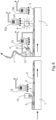
- FIG. 8 shows a device in the form of a production line.
- Two workpieces 1 are shown, which are moved one after the other in the direction of movement from left to right.
- a transport device (not shown) is provided for this purpose.
- the workpiece 1 has a liquid layer 2 on its surface.
- a means of manipulation 3 is contained in and/or on the layer 2 .
- the following elements are arranged one after the other from left to right in the direction of movement.
- a stationary contact element is arranged in the form of a brush 15 which is designed to come into contact with the surface of the layer 2 in order to remove parts of the layer 2 mechanically. What is thereby achieved here in particular is that means of manipulation 3 enclosed in layer 2 are uncovered.
- Downstream of the brush 15 is a radiation source 12 which is designed to emit UV radiation in the direction of the workpiece 1 or the layer 2 in order to at least partially harden the layer 2 .
- An element is then provided in the direction of movement, which has a chamber 4 through which the workpiece 1 is moved.
- the chamber 4 initially has a nozzle 6 which, counter to the direction of movement of the workpiece 1, emits a fluid flow at an angle to the surface of the layer 2 gives.
- the angle is a maximum of 90° or less.
- the angle is preferably adjusted between 0° and 30°. This adaptation can take place, for example, as a function of the removed material of the manipulation means and/or as a function of the removed material of layer 2 .
- the fluid flow contains solids as described above in order to remove parts 13 of layer 2 .
- the chamber also has a suction device 7 which is designed to suck up loosened parts 13 of the layer 2 .
- a radiation source 12 which is designed to irradiate the layer 2 with radiation in order to partially cure it, so that the viscosity of the layer 2 changes.
- the radiation can be, for example, UV radiation with a wavelength of 200 to 400 nm.
- the fluid flow is designed in such a way that it extends over the entire width of the workpiece 1, i.e. in a direction of extension of the workpiece 1 perpendicular to the plane of the drawing. This ensures that all areas of layer 2 are covered by the fluid flow.
- a liquid or a gaseous substance is used as the fluid.
- water and/or air can also be used as the fluid.
- a contact element with a brush 8 in the form of a roller brush is arranged downstream of the chamber 4 .
- the brush 8 is designed to remove parts of the layer 2 mechanically.
- a radiation source 12a is arranged above the brush, for example UV radiation on the brush 8 releases.
- the cleaning of the brush 8 can essentially correspond to the description 7 take place.
- a further radiation source 12b is arranged downstream of the brush 8 in the direction of movement. This emits, for example, UV radiation onto the layer 2 and possibly desired manipulation means 3 contained therein in order to carry out a final curing.
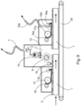
- Two workpieces 1 are shown, which are moved from left to right by a transport device with a belt transport 20 .
- a layer 2 is applied to the workpieces 1 .
- a cleaning agent 16 is first applied to the layer 2 with the aid of an application device 17, which has an application roller here. This cleaning agent 16 is then at least partially removed again with a scraper 18 . Parts of the layer 2 are then removed with a standing contact element 15 and a brush 8, with a UV radiation source 12 being provided to irradiate the brush 8 and the contact element 15 in order to harden material from removed parts of the layer 2 adhering thereto or to become brittle. With the help of a suction device 7, these parts 13 are continuously sucked off as described above. In addition, as in 7 described, a scraping edge (not shown) may be provided.
- the device for removing the cleaning agent 16a has a scraper 18a, which is in contact with the surface of the layer 2, and a suction device 19a.
- the suction device 19a is designed to suck off and discharge the cleaning agent 16a that is retained on the scraper 18a.
- Such a suction device for removing the cleaning agent 16 can also be provided on the first scraper 18 .
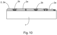
- FIG. 10 shows a workpiece 1 with a layer 2 on the surface of the workpiece 1, the layer 2 having been at least partially hardened and now having areas 2a with a higher degree of hardness, and areas 2b with a lower degree of hardness, these areas increasing in degree of hardness by a factor of at least 1.5, preferably at least 2.
- the workpiece 1 shown here with the layer 2 is further processed, for example, in a method for surface processing described above.
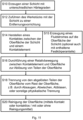
- FIG. 11 shows an exemplary flowchart of a method.
- step S12 the workpiece with the layer is moved to a removal device.
- step S14 a contact is established between the surface of the layer and a contact element of the removal device.
- step S15 a fluid flow with an optional solids content is generated, which acts on the surface of the layer, as a result of which parts of the layer are removed or detached.
- step S16 after contact has been established between the surface of the layer and a contact element, a relative movement is carried out between the contact element and the surface according to step S14, as a result of which parts of the layer are removed or detached.
- step S18 the detached parts of the surface of the layer are separated from the remaining layer. This can be done, for example, by suction, wiping or blowing off or by any other suitable measure.
- step S20 the surface of the layer is cleaned by means of contact or also without contact and/or by using a cleaning agent.
- the method can be further developed by swapping, omitting and/or repeating individual steps and by adding further steps.
- the invention is not limited to the embodiments shown here. Rather, further devices and/or methods can be obtained which also correspond to the invention by combining individual features with one another, exchanging them or omitting them.
- the configuration can 7 into the production line 8 be additionally integrated, or be provided instead of the chamber 4 and / or the brush 8 shown here.
- All nozzles 6 in the figures 1 and 8th may be configured to deliver a fluid stream with or without solids as described above.
- the fluid stream may contain a gas and/or a liquid, specifically containing air and/or water.
- the radiation sources shown in all the figures can be designed to also emit other radiation, such as electron beams, as an alternative or in addition to electromagnetic radiation, in particular UV radiation.
- the type of radiation and/or the corresponding wavelength are selected depending on the material composition of layer 2 and/or manipulation means 3 and/or depending on the desired effect of the radiation on layer 2 and/or manipulation means 3 .
- a different wavelength and/or radiation can be used than when in one only the viscosity of the layer 2 is to be changed in the preceding step, for example to prevent the indentations introduced by the manipulation means 3 from running.
- All of the embodiments of the invention shown here, which have at least one brush 8, can also be designed such that the at least one brush 8 is movably provided. This means that the at least one brush 8 can be actively moved through a predefined movement pattern.
- a plate brush can be provided on a pivotable suspension.
- a third aspect of the invention there is provided a method according to the first and second aspects, wherein each of the steps of the method is carried out at least once.
- the layer 2 on the surface of the workpiece 1 has hardness differences of at least a factor of 1.5, preferably at least a factor of 2, between harder areas 2a and less hard areas 2b.
- a fifth aspect of the invention there is provided a method according to any one of the preceding aspects, wherein the physical separation of the detached parts 13 of the layer 2 from the parts of the layer 2 remaining on the surface of the workpiece 1 is carried out by suction, wiping, blowing off, or by a combination of these steps.
- a sixth aspect of the invention there is provided a method according to one of the preceding aspects and in particular according to the first, third, fourth or fifth aspect, wherein the layer 2, which is on the surface of the workpiece 1, and the contact element move relative to each other when removing parts of the layer.
- an eighth aspect of the invention there is provided a method according to any one of the preceding aspects, wherein simultaneously with the establishment of the mechanical contact between the contact element and the layer 2 on the surface and/or simultaneously with the generation of the fluid flow onto the layer 2, an irradiation of the layer 2 and/or the contact element and/or the surroundings of the contact element in the separate parts of the layer 2 are located, preferably with electromagnetic radiation.
- a ninth aspect of the invention there is provided a method according to one of the preceding aspects and in particular according to the first, third, fourth, fifth, sixth, seventh or eighth aspect, wherein the contact element 8, 15 is continuously cleaned during the physical separation, the cleaning preferably being carried out by using a combination of an electromagnetic radiation source 5, 12 and/or a suction device 7, 7a and/or a mechanical knock-off edge 14.
- a method according to one of the above aspects and in particular according to the second, third, fourth, fifth, sixth, seventh, eighth or ninth aspect is provided, wherein a nozzle 6, which is designed to generate the fluid flow, is continuously cleaned during the physical separation, the cleaning preferably being carried out by a combination of an electromagnetic radiation source 5, 12 and/or a suction device 7, 7a and/or one or more further drying devices or radiation sources 5, 12 is carried out.
- a method according to one of the above aspects and in particular according to the first, third, fourth, fifth, sixth, seventh, eighth, ninth or tenth aspect is provided, wherein before establishing the mechanical contact between the contact element and the layer 2, the surface of the layer 2 is cleaned, and/or wherein after the physical separation of parts of the layer 2, the remaining layer 2 remaining on the surface of the workpiece 1 is cleaned becomes.
- a method is provided according to one of the preceding aspects and in particular according to the second, third, fourth, fifth, sixth, seventh, eighth, ninth, tenth or eleventh aspect, wherein cleaning of the surface is carried out before the fluid flow onto layer 2 is generated, and/or cleaning of the remaining layer 2 remaining on the surface of workpiece 1 is carried out after parts of layer 2 have been physically separated.
- a method according to the ninth, tenth, eleventh or twelfth aspect wherein the continuous cleaning of the contact element, in particular the brush 8, by irradiation with UV radiation, preferably with a wavelength between 180 and 400 nm, in combination with scraping off hardened residual components 13 from the separated parts of the layer 2 at a knock-off edge 14 and a suction device of these residual components 13 takes place with the aid of a suction device 7, 7a.
- a fourteenth aspect of the invention there is provided a method according to the tenth, eleventh, twelfth or thirteenth aspect, wherein the nozzle 6 is continuously cleaned by irradiation with UV radiation, preferably with a wavelength between 180 and 400 nm, in combination with sucking off residual components 13 from the separated parts of the layer 2 using a suction device 7, 7a.
- a cleaning agent 16 is applied to the layer, which is then preferably removed again, particularly preferably with the aid of a scraper 18 and/or a suction device 19.
Landscapes
- Engineering & Computer Science (AREA)
- Mechanical Engineering (AREA)
- Life Sciences & Earth Sciences (AREA)
- Toxicology (AREA)
- Health & Medical Sciences (AREA)
- Wood Science & Technology (AREA)
- Manufacturing & Machinery (AREA)
- Forests & Forestry (AREA)
- Physics & Mathematics (AREA)
- Plasma & Fusion (AREA)
- Application Of Or Painting With Fluid Materials (AREA)
- Grinding Of Cylindrical And Plane Surfaces (AREA)
- Chemically Coating (AREA)
- Turning (AREA)
- Physical Or Chemical Processes And Apparatus (AREA)
Applications Claiming Priority (2)
| Application Number | Priority Date | Filing Date | Title |
|---|---|---|---|
| DE102019206431.0A DE102019206431A1 (de) | 2019-05-03 | 2019-05-03 | Verfahren zum Herstellen einer Struktur auf einer Oberfläche |
| EP19208741.9A EP3733308B1 (fr) | 2019-05-03 | 2019-11-12 | Procédé et dispositif d'usinage de surfaces |
Related Parent Applications (2)
| Application Number | Title | Priority Date | Filing Date |
|---|---|---|---|
| EP19208741.9A Division-Into EP3733308B1 (fr) | 2019-05-03 | 2019-11-12 | Procédé et dispositif d'usinage de surfaces |
| EP19208741.9A Division EP3733308B1 (fr) | 2019-05-03 | 2019-11-12 | Procédé et dispositif d'usinage de surfaces |
Publications (1)
| Publication Number | Publication Date |
|---|---|
| EP4212254A1 true EP4212254A1 (fr) | 2023-07-19 |
Family
ID=68581334
Family Applications (5)
| Application Number | Title | Priority Date | Filing Date |
|---|---|---|---|
| EP23159373.2A Pending EP4212254A1 (fr) | 2019-05-03 | 2019-11-12 | Procédé et dispositif de traitement de surface |
| EP19208741.9A Active EP3733308B1 (fr) | 2019-05-03 | 2019-11-12 | Procédé et dispositif d'usinage de surfaces |
| EP19208738.5A Active EP3733307B1 (fr) | 2019-05-03 | 2019-11-12 | Procédé et dispositif de production d'une surface décorative |
| EP20724447.6A Pending EP3752296A2 (fr) | 2019-05-03 | 2020-05-04 | Procédé pour réaliser une structure sur une surface |
| EP23160613.8A Pending EP4215282A1 (fr) | 2019-05-03 | 2020-05-04 | Procédé de fabrication d'une structure sur une surface |
Family Applications After (4)
| Application Number | Title | Priority Date | Filing Date |
|---|---|---|---|
| EP19208741.9A Active EP3733308B1 (fr) | 2019-05-03 | 2019-11-12 | Procédé et dispositif d'usinage de surfaces |
| EP19208738.5A Active EP3733307B1 (fr) | 2019-05-03 | 2019-11-12 | Procédé et dispositif de production d'une surface décorative |
| EP20724447.6A Pending EP3752296A2 (fr) | 2019-05-03 | 2020-05-04 | Procédé pour réaliser une structure sur une surface |
| EP23160613.8A Pending EP4215282A1 (fr) | 2019-05-03 | 2020-05-04 | Procédé de fabrication d'une structure sur une surface |
Country Status (8)
| Country | Link |
|---|---|
| US (4) | US20200346484A1 (fr) |
| EP (5) | EP4212254A1 (fr) |
| KR (1) | KR102798285B1 (fr) |
| CN (3) | CN114174076A (fr) |
| DE (1) | DE102019206431A1 (fr) |
| ES (2) | ES2964229T3 (fr) |
| PL (2) | PL3733308T3 (fr) |
| WO (3) | WO2020225215A2 (fr) |
Families Citing this family (16)
| Publication number | Priority date | Publication date | Assignee | Title |
|---|---|---|---|---|
| ES2971866T3 (es) | 2017-06-13 | 2024-06-10 | Hymmen Gmbh Maschinen & Anlagenbau | Procedimiento y dispositivo de producción de una superficie estructurada |
| WO2019226885A1 (fr) * | 2018-05-25 | 2019-11-28 | Corning Incorporated | Procédés de modification d'un substrat par déformation élastocapillaire |
| AU2019333292B2 (en) | 2018-08-30 | 2023-11-23 | Interface, Inc. | Digital printing for flooring and decorative structures |
| DE102019206431A1 (de) | 2019-05-03 | 2020-11-05 | Hymmen GmbH Maschinen- und Anlagenbau | Verfahren zum Herstellen einer Struktur auf einer Oberfläche |
| PL4049851T3 (pl) * | 2021-02-26 | 2024-11-25 | Jesús Francisco Barberan Latorre | Sposób i system wytwarzania reliefu na podłożu |
| CN113021192A (zh) * | 2021-03-02 | 2021-06-25 | 超安(广州)五金有限公司 | 一种控制金属原子活动性的节能环保硅片处理设备 |
| DE102021113681A1 (de) | 2021-05-27 | 2022-12-01 | Homag Gmbh | Vorrichtung und Verfahren zum Veredeln eines Werkstücks |
| JP2024522676A (ja) * | 2021-06-25 | 2024-06-21 | クンディグ アクチエンゲゼルシャフト | エアブレードにより吹き飛ばしを行うことによる研磨ベルトの清掃方法、およびエアブレード |
| EP4129711B1 (fr) | 2021-08-05 | 2026-04-08 | Unilin, BV | Procédé de fabrication d'un produit comprenant une couche de surface décorative |
| EP4201696A1 (fr) | 2021-12-22 | 2023-06-28 | Flooring Industries Limited, SARL | Procédé de création d'une couche texturée sur un panneau décoratif |
| EP4215382B1 (fr) | 2022-01-24 | 2026-01-21 | Unilin, BV | Un procédé de fabrication d'un panneau |
| IT202200008756A1 (it) | 2022-05-02 | 2023-11-02 | Cefla Soc Cooperativa | Metodo e apparato per formare una struttura superficiale |
| CN120202085A (zh) * | 2022-09-15 | 2025-06-24 | 阿莱恩技术有限公司 | 用于对增材制造对象的表面进行改性的系统和方法 |
| LU504519B1 (en) | 2023-06-15 | 2024-12-16 | Tarkett Gdl Sa | Surface covering panel with transitional edge |
| LU504655B1 (en) | 2023-07-03 | 2025-01-03 | Tarkett Gdl Sa | Decorative surface coverings digitally embossed |
| LU506092B1 (en) | 2024-01-12 | 2025-07-14 | Tarkett Gdl Sa | Three-Dimensional Surface Texturing |
Citations (12)
| Publication number | Priority date | Publication date | Assignee | Title |
|---|---|---|---|---|
| JPS59169575A (ja) * | 1983-03-16 | 1984-09-25 | Kyushu Hitachi Maxell Ltd | 塗料の剥離方法 |
| EP1101542A2 (fr) * | 1999-11-15 | 2001-05-23 | WANDRES GmbH MICRO-CLEANING | Procédé et dispositif pour enlever des contaminants de surfaces contaminées par un liquide |
| DE69709984T2 (de) * | 1996-05-29 | 2002-09-26 | Shinko Co. Ltd., Osaka | System zur Entfernung von Staub |
| EP2280130A2 (fr) | 2000-06-13 | 2011-02-02 | Flooring Industries Ltd. | Revêtement de sol |
| EP2343169A2 (fr) * | 2005-02-23 | 2011-07-13 | Flooring Industries Ltd. | Procédé de fabrication de panneaux de plancher et équipement pour traiter les matériaux stratifiés en forme de tableau |
| JP2011173091A (ja) * | 2010-02-25 | 2011-09-08 | Tokyo Electron Ltd | 塗布装置及びノズル洗浄方法 |
| DE102010052518A1 (de) * | 2010-11-26 | 2012-05-31 | Brillux Gmbh & Co. Kg | Beschichtungsmasse mit Funkeleffekt |
| US20160114619A1 (en) * | 2008-12-19 | 2016-04-28 | Flooring Industries Limited, Sarl | Methods for manufacturing panels and panel obtained thereby |
| EP3109056A1 (fr) | 2015-06-25 | 2016-12-28 | Hymmen GmbH Maschinen- und Anlagenbau | Procede et dispositif de fabrication d'une structure sur une surface |
| JP2017200740A (ja) * | 2016-05-06 | 2017-11-09 | 株式会社リコー | 液体吐出ユニット及び液体吐出装置 |
| US20170333936A1 (en) * | 2009-08-07 | 2017-11-23 | Fas Holdings Group, Llc | Segmented or selected-area coating |
| EP3415316A1 (fr) | 2017-06-13 | 2018-12-19 | Hymmen GmbH Maschinen- und Anlagenbau | Procédé et dispositif de fabrication d'une surface structurée |
Family Cites Families (175)
| Publication number | Priority date | Publication date | Assignee | Title |
|---|---|---|---|---|
| US692701A (en) | 1901-01-15 | 1902-02-04 | Bradley & Hubbard Mfg Co | Lamp-burner. |
| US3308227A (en) | 1964-04-20 | 1967-03-07 | Formica Corp | Process for making embossed laminates |
| US3580768A (en) * | 1967-11-29 | 1971-05-25 | Stanley Kukla | Method of forming decorative three dimensional effect designs and coatings |
| FR2017059A1 (en) | 1968-08-28 | 1970-05-15 | Cartiere Ambrogio Binda Spa | Impregnated paper coatings for wooden surface |
| US3676963A (en) | 1971-03-08 | 1972-07-18 | Chemotronics International Inc | Method for the removal of unwanted portions of an article |
| GB1405643A (en) | 1972-10-26 | 1975-09-10 | Formica Int | Decorative sheet material and process for producing same |
| DE2919847B1 (de) | 1979-05-16 | 1980-10-16 | Lissmann Alkor Werk | Flaechengebilde mit Holzmaserung und Verfahren zu dessen Herstellung |
| US4439480A (en) | 1980-10-01 | 1984-03-27 | Tarkett Ab | Radiation cured coating and process therefor |
| DE3107798A1 (de) | 1981-02-28 | 1982-09-16 | wf rational Anbauküchen GmbH + Co, 4520 Melle | Gedruckte nachbildung von naturholzstreifen und verfahren zur herstellung von eindruecken |
| DE3247146C1 (de) | 1982-12-21 | 1984-03-22 | Held, Kurt, 7218 Trossingen | Verfahren und Vorrichtung zur kontinuierlichen Herstellung von Schichtpress-Stoffen |
| DE3331391A1 (de) * | 1983-08-31 | 1985-03-07 | Dieter 6636 Berus Schmitt | Verfahren zum herstellen von metallisch wirkenden ueberzuegen auf oberflaechen aus polystyrol |
| US4513299A (en) | 1983-12-16 | 1985-04-23 | International Business Machines Corporation | Spot size modulation using multiple pulse resonance drop ejection |
| DE3510415A1 (de) | 1985-03-22 | 1986-09-25 | Schering AG, 1000 Berlin und 4709 Bergkamen | Verwendung von polyamidharzen fuer den reliefdruck |
| DE3527404C1 (de) | 1985-07-31 | 1987-01-02 | Kurz Leonhard Fa | Verfahren zur Herstellung einer eine texturierte Lackschicht aufweisenden Folie |
| AT387621B (de) | 1987-03-10 | 1989-02-27 | Dana Tuerenindustrie | Verfahren zur herstellung eines tuerblattes mit insbesondere linienartigen verzierungen |
| US5178928A (en) | 1988-09-22 | 1993-01-12 | Dai Nippon Insatsu Kabushiki Kaisha | Decorative materials |
| EP0372097A1 (fr) | 1988-11-30 | 1990-06-13 | Siemens Aktiengesellschaft | Dispositif pour la formation de gouttelettes d'encre dans une imprimante à gouttelettes d'encre |
| EP0428628A1 (fr) | 1989-06-12 | 1991-05-29 | General Electric Company | Unite d'impression laminaire de rev tement de substrats plats |
| EP0499720B1 (fr) | 1991-02-20 | 1996-05-22 | Agfa-Gevaert N.V. | Système pour réduire la contamination de rouleaux et/ou de supports |
| ES1018178Y (es) | 1991-05-03 | 1992-08-01 | Barberan, S.A. | Equipo de recuperacion y limpieza para el transportador de una instalacion de proyeccion de tintes o barnices. |
| DE4139961A1 (de) | 1991-12-04 | 1993-06-09 | Basf Ag, 6700 Ludwigshafen, De | Traenkharzloesung zum impraegnieren von papierbahnen |
| JPH0767800B2 (ja) * | 1991-12-16 | 1995-07-26 | ニッカ株式会社 | 印刷シリンダの洗浄装置 |
| JP3133476B2 (ja) * | 1992-04-03 | 2001-02-05 | 大日本印刷株式会社 | エンボス版、該エンボス版を用いて製造した化粧材及び該エンボス版の製造方法 |
| JPH0775889B2 (ja) * | 1992-10-06 | 1995-08-16 | 日本ボールドウィン株式会社 | シリンダ洗浄装置 |
| US5621022A (en) * | 1992-11-25 | 1997-04-15 | Tektronix, Inc. | Use of polymeric dyes in hot melt ink jet inks |
| JPH06270372A (ja) | 1993-03-17 | 1994-09-27 | Dainippon Printing Co Ltd | 凹凸模様を有する化粧材 |
| US5498460A (en) * | 1993-03-24 | 1996-03-12 | Tingley; Daniel A. | Surface treated synthetic reinforcement for structural wood members |
| DE4421559C2 (de) | 1994-06-20 | 1998-05-20 | Osmetric Entwicklungs Und Prod | Verfahren zum Herstellen einer Beschichtung, die eine Struktur aufweist, auf einem Substrat sowie Beschichtung |
| CN1082444C (zh) | 1994-12-29 | 2002-04-10 | 佳能株式会社 | 采用具有多个喷墨加热器的喷墨头的喷墨设备 |
| DE19532819A1 (de) | 1995-09-06 | 1997-03-13 | Hofa Homann Verwaltungsgesells | Verfahren zur Herstellung einer Holzwerkstoffplatte |
| JPH09323434A (ja) | 1996-04-02 | 1997-12-16 | Toray Ind Inc | 建材のプリント装置及びプリントずみ建材の製造方法 |
| JP2000516872A (ja) | 1996-08-27 | 2000-12-19 | トパーズ・テクノロジーズ・インコーポレイテッド | 可変体積のインク滴を生成するインクジェットプリントヘッド |
| EP1332876B1 (fr) | 1996-09-09 | 2006-03-22 | Seiko Epson Corporation | Imprimante à jet d'encre et méthode d'impression |
| US5779779A (en) | 1996-09-27 | 1998-07-14 | Dataproducts Corporation | UV-blocking hot melt inks |
| SE9703281L (sv) | 1997-09-11 | 1999-03-12 | Perstorp Ab | Förfarande för framställning av härdplastlaminat |
| DE19810455C2 (de) | 1998-03-11 | 2000-02-24 | Michael Bisges | Kaltlicht-UV-Bestrahlungsvorrichtung |
| EP1089986B1 (fr) | 1998-06-22 | 2005-03-30 | Ciba SC Holding AG | Absorbeurs de lumiere ultraviolette a base de poly-trisaryl-1,3,5-triazine carbamate |
| US6150009A (en) | 1998-08-07 | 2000-11-21 | Surface Technologies, Inc. | Decorative structural panel |
| GB9825359D0 (en) | 1998-11-20 | 1999-01-13 | Xaar Technology Ltd | Methods of inkjet printing |
| US6120845A (en) | 1999-01-20 | 2000-09-19 | Pease; Scott Norton | Method for applying a decorative finish to the surface of an object |
| JP3223901B2 (ja) | 1999-01-25 | 2001-10-29 | 日本電気株式会社 | インクジェット記録ヘッドの駆動方法及びその回路 |
| US6193361B1 (en) | 1999-06-03 | 2001-02-27 | Eastman Kodak Company | Apparatus for forming textured layers over images |
| IL130458A (en) | 1999-06-14 | 2006-07-05 | Kodak Il Ltd | Digital imaging method for creating the web for use in web printing |
| JP3446686B2 (ja) | 1999-10-21 | 2003-09-16 | セイコーエプソン株式会社 | インクジェット式記録装置 |
| US8209928B2 (en) | 1999-12-13 | 2012-07-03 | Faus Group | Embossed-in-registration flooring system |
| SE516696C2 (sv) | 1999-12-23 | 2002-02-12 | Perstorp Flooring Ab | Förfarande för framställning av ytelement vilka innefattar ett övre dekorativt skikt samt ytelement framställda enlit förfarandet |
| US6431676B2 (en) | 2000-01-28 | 2002-08-13 | Seiko Epson Corporation | Generation of driving waveforms to actuate driving elements of print head |
| EP1149712A1 (fr) | 2000-04-25 | 2001-10-31 | Tarkett Sommer S.A. | Procédé de production de revêtements de sols et de murs à effet de décor de brillance différentiel et produits obtenus |
| DE10031030B4 (de) | 2000-06-26 | 2005-08-04 | Bauer, Jörg R. | Verfahren und Vorrichtung zum Herstellen flächiger Bauteile mit vorbestimmtem Oberflächenaussehen und flächiges Bauteil, insbesondere Frontplatte eines Küchenelements |
| DE10035961A1 (de) | 2000-07-24 | 2002-02-07 | Basf Ag | Verfahren zum Beschichten von Substraten |
| GB2367788A (en) | 2000-10-16 | 2002-04-17 | Seiko Epson Corp | Etching using an ink jet print head |
| AU2002239731A1 (en) * | 2000-11-13 | 2002-06-03 | Imaging Alternatives, Inc. | Wood surface inkjet receptor medium and method of making and using same |
| ITPS20010006A1 (it) | 2001-02-23 | 2002-08-23 | Canti & Figli Srl | Procedimento e macchina atti ad ottenere goffrature su superfici verniciate di pannelli o di pellicole di rivestimento ed elementi ottenuti |
| DE10134188A1 (de) | 2001-07-13 | 2003-01-23 | Heidelberger Druckmasch Ag | Tintenstrahl-Drucksystem |
| JP3996418B2 (ja) | 2002-03-28 | 2007-10-24 | アトミクス株式会社 | 塗膜層の作製方法 |
| KR100958753B1 (ko) | 2002-04-03 | 2010-05-19 | 메이소나이트 코오포레이션 | 물품에 상을 만드는 방법 및 장치 그리고 인쇄된 물품 |
| KR100455546B1 (ko) | 2002-04-19 | 2004-11-06 | 신현덕 | 인쇄 나무 마루판 |
| US7067241B2 (en) | 2002-05-08 | 2006-06-27 | Unaxis Balzers Aktiengesellschaft | Method for producing a unit having a three-dimensional surface patterning, and use of this method |
| DE10224128A1 (de) | 2002-05-29 | 2003-12-18 | Schmid Rhyner Ag Adliswil | Verfahren zum Auftrag von Beschichtungen auf Oberflächen |
| JP4157336B2 (ja) | 2002-07-15 | 2008-10-01 | 東芝テック株式会社 | インクジェット記録装置 |
| DE60200552T3 (de) | 2002-07-26 | 2012-02-09 | Banque Nationale De Belgique S.A. | Verfahren um latente Bilder zu drucken |
| JP4689155B2 (ja) | 2002-08-29 | 2011-05-25 | 株式会社半導体エネルギー研究所 | 半導体装置の作製方法 |
| US20040086678A1 (en) | 2002-11-01 | 2004-05-06 | Chen Hao A. | Surface covering panel |
| EP1449667A1 (fr) | 2003-02-21 | 2004-08-25 | Agfa-Gevaert | Procédé et dispositif pour imprimer des images à échelle de gris |
| DE10310199B4 (de) | 2003-03-06 | 2007-09-20 | Kronotec Ag | Holzfaserplatte und Verfahren zu deren Herstellung |
| DE10316695B4 (de) | 2003-04-10 | 2006-12-28 | Theodor Hymmen Holding Gmbh | Verfahren und Vorrichtung zur Herstellung eines Laminats |
| US7419716B2 (en) | 2003-05-30 | 2008-09-02 | Awi Licensing Company | Multiple gloss level surface coverings and method of making |
| US7470455B2 (en) | 2003-11-18 | 2008-12-30 | Art Guitar, Llc | Decorating guitars |
| CA2568440C (fr) | 2004-05-28 | 2015-05-05 | Kronotec Ag | Panneau en materiau derive du bois presentant un revetement de surface |
| KR20060004828A (ko) | 2004-07-10 | 2006-01-16 | (주)아도니스마루 | 마루판 및 그 제조방법 |
| ES2545665T3 (es) | 2004-10-05 | 2015-09-14 | Fritz Egger Gmbh & Co. Og | Procedimiento para producir una superficie estructurada y una placa con una superficie estructurada |
| US20060075917A1 (en) | 2004-10-08 | 2006-04-13 | Edwards Paul A | Smooth finish UV ink system and method |
| EP1652686B1 (fr) | 2004-10-29 | 2008-06-25 | Agfa Graphics N.V. | Impression d'encres durcissables par rayonnement sur une couche liquide durcissable par rayonnement |
| BRPI0519338A2 (pt) | 2004-12-16 | 2009-01-20 | Flooring Ind Ltd | painel de piso e mÉtodo para fabricar um painel de piso |
| DE102005003839A1 (de) | 2005-01-27 | 2006-08-03 | Koenig & Bauer Ag | Sicherheitsmarkierung |
| JP5046387B2 (ja) | 2005-01-27 | 2012-10-10 | 国立大学法人北海道大学 | ハニカム構造体の製造方法 |
| JP4720226B2 (ja) | 2005-03-15 | 2011-07-13 | 富士ゼロックス株式会社 | 液滴吐出記録ヘッドの駆動方法及び液滴吐出記録装置 |
| JP4631506B2 (ja) | 2005-03-30 | 2011-02-16 | セイコーエプソン株式会社 | 液体噴射装置 |
| US7575293B2 (en) | 2005-05-31 | 2009-08-18 | Xerox Corporation | Dual drop printing mode using full length waveforms to achieve head drop mass differences |
| GB0517931D0 (en) | 2005-09-02 | 2005-10-12 | Xaar Technology Ltd | Method of printing |
| RU2306228C2 (ru) | 2005-10-19 | 2007-09-20 | Производственное общество с ограниченной ответственностью "ФОКС" | Способ получения декоративного изображения |
| JP2007175962A (ja) | 2005-12-27 | 2007-07-12 | Fujifilm Corp | 撥液性構造体およびその製造方法、液体吐出ヘッドならびに保護フィルム |
| DE102006003798A1 (de) | 2006-01-25 | 2007-07-26 | Man Roland Druckmaschinen Ag | Verfahren und Einrichtung zum Erzeugen von betrachtungswinkelabhängig veränderbaren Bildeffekten auf einen Bedruckstoff |
| FI20065083A0 (fi) | 2006-02-03 | 2006-02-03 | Upm Kymmene Wood Oy | Menetelmä puulevyn pinnoittamiseksi ja puulevy |
| US7384568B2 (en) * | 2006-03-31 | 2008-06-10 | Palo Alto Research Center Incorporated | Method of forming a darkfield etch mask |
| US7918062B2 (en) | 2006-06-08 | 2011-04-05 | Mannington Mills, Inc. | Methods and systems for decorating bevel and other surfaces of laminated floorings |
| JP4907419B2 (ja) | 2006-06-21 | 2012-03-28 | 富士フイルム株式会社 | インクジェット記録方法及びインクジェット記録装置 |
| ITMI20061227A1 (it) | 2006-06-26 | 2007-12-27 | Dante Frati | Procedimento per stampare superfici di elementi piani a base di legno |
| CN100548602C (zh) | 2006-08-17 | 2009-10-14 | 宁波大榭开发区达因圣马克家俱有限公司 | 一种装饰板的加工方法 |
| DE102006042063B4 (de) | 2006-09-05 | 2022-04-07 | Wilhelm Taubert GmbH | Verfahren zur Einstellung des Glanzgrades und der Haptik von dekorativen und funktionellen Oberflächen |
| JP4903618B2 (ja) | 2006-09-25 | 2012-03-28 | 富士フイルム株式会社 | インクジェット記録方法及びインクジェット記録装置 |
| JP4813413B2 (ja) | 2006-09-28 | 2011-11-09 | 富士フイルム株式会社 | インクジェット記録方法及びインクジェット記録装置 |
| JP4907414B2 (ja) | 2006-09-29 | 2012-03-28 | 富士フイルム株式会社 | インクジェット記録方法及びインクジェット記録装置 |
| JP2008093910A (ja) | 2006-10-10 | 2008-04-24 | Hokusan Kk | インクジェット印刷されてなる化粧材 |
| ES2421155T3 (es) | 2006-10-12 | 2013-08-29 | Agfa Graphics N.V. | Método para operar un cabezal de impresión por inyección de tinta |
| US7988247B2 (en) | 2007-01-11 | 2011-08-02 | Fujifilm Dimatix, Inc. | Ejection of drops having variable drop size from an ink jet printer |
| EP1952998B1 (fr) | 2007-02-01 | 2011-04-06 | FUJIFILM Corporation | Appareil d'enregistrement à jet d'encre |
| US8541063B2 (en) | 2007-02-06 | 2013-09-24 | Fujifilm Corporation | Undercoat solution, ink-jet recording method and ink-jet recording device |
| BE1018432A5 (nl) | 2007-03-14 | 2010-11-09 | Flooring Ind Ltd | Werkwijzen voor het vervaardigen van laminaat, inrichting hierbij aangewend, laminaat hierbij verkregen, werkwijze voor het ommantelen van substraten en ommanteld substraat hierbij verkregen. |
| JP2008246993A (ja) * | 2007-03-30 | 2008-10-16 | Fujifilm Corp | インクジェット記録装置及びインクジェット記録方法 |
| JP2008254237A (ja) | 2007-04-02 | 2008-10-23 | Toppan Cosmo Inc | 化粧材 |
| DE102007019871A1 (de) * | 2007-04-25 | 2008-10-09 | Theodor Hymmen Holding Gmbh | Verfahren und Vorrichtung zur Erzeugung einer dünnen dreidimensional strukturierten Oberfläche auf plattenförmigen Werkstoffen |
| EP1990204B1 (fr) | 2007-05-10 | 2015-12-02 | Homag Holzbearbeitungssysteme AG | Procédé et dispositif de revêtement d'une surface |
| CN101314981A (zh) | 2007-05-29 | 2008-12-03 | 汪宏伟 | Uv饰面装饰板及其制作工艺 |
| CN101342844B (zh) | 2007-07-10 | 2013-06-19 | 豪迈木材加工系统公司 | 工件表面装饰装置 |
| JP4898618B2 (ja) | 2007-09-28 | 2012-03-21 | 富士フイルム株式会社 | インクジェット記録方法 |
| US8574678B2 (en) * | 2007-10-16 | 2013-11-05 | Dallaire Industries Ltd. | Method of texturing synthetic material extrusions |
| DE202007014736U1 (de) | 2007-10-19 | 2007-12-20 | Robert Bürkle GmbH | Vorrichtung zum Herstellen einer strukturierten Oberfläche einer lackierten Werkstoffplatte |
| DE102007055053A1 (de) | 2007-11-16 | 2009-05-20 | Hueck Engraving Gmbh & Co. Kg | Verfahren zur Bearbeitung einer strukturierten Oberfläche |
| KR101064427B1 (ko) | 2007-12-20 | 2011-09-14 | (주)엘지하우시스 | 모자이크 인쇄층을 갖는 마루바닥재 |
| JP2009208348A (ja) | 2008-03-04 | 2009-09-17 | Fujifilm Corp | 画像形成装置及び画像形成方法 |
| ES2340456B1 (es) | 2008-03-18 | 2011-02-02 | Jesus Fco. Barberan Latorre | Procedimiento de impresion por inyeccion de tinta sobre substrato humedo. |
| JP4990207B2 (ja) | 2008-03-31 | 2012-08-01 | 富士フイルム株式会社 | 多孔フィルムの製造方法 |
| DE102008024149B4 (de) | 2008-05-19 | 2011-06-22 | Institut für Oberflächenmodifizierung e.V., 04318 | Vorrichtung zur Ermittlung der Faltungskinetik und der Faltungsgeschwindigkeit strahlenhärtbarer Farben und Lacke während des Prozesses der photochemische Mikrofaltung initiiert durch kurzwellige monochromatische Excimer-UV-Strahlung |
| JP4758497B2 (ja) | 2008-07-10 | 2011-08-31 | 株式会社リコー | 洗浄装置及び洗浄方法 |
| JP5016716B2 (ja) | 2008-08-21 | 2012-09-05 | ローランドディー.ジー.株式会社 | インクジェット式記録装置およびコンピュータプログラム |
| JP5294770B2 (ja) | 2008-09-17 | 2013-09-18 | 株式会社秀峰 | 立体感のある色彩被覆の作成方法およびそれによる立体的色彩印刷体 |
| FR2937181B1 (fr) | 2008-10-10 | 2011-01-14 | Commissariat Energie Atomique | Structuration en surface de couches minces par ejection localisee de liquide immiscible. |
| FR2936965A1 (fr) | 2008-10-10 | 2010-04-16 | Commissariat Energie Atomique | Formation de via traversant des couches minces par ejection localisee de liquide immiscible. |
| EP2181860B1 (fr) | 2008-10-22 | 2013-03-20 | Fritz Egger GmbH & Co. OG | Composant en matière dérivée du bois doté de propriétés tactiles particulières et procédé de fabrication d'un tel composant |
| KR101679171B1 (ko) | 2008-12-19 | 2016-11-23 | 플로어링 인더스트리즈 리미티드 에스에이알엘 | 코팅 패널 및 이러한 패널의 제조 방법 |
| DE102009004482B4 (de) | 2009-01-09 | 2012-03-29 | Fritz Egger Gmbh & Co. | Bauelement aus Holzwerkstoff mit aufgedrucktem Dekor und unterschiedlichem Glanzgrad |
| ES2349527B1 (es) | 2009-03-31 | 2011-10-27 | Tecser Print. S.L.L. | Procedimiento para la impresion con efecto brillante. |
| KR20100120434A (ko) | 2009-05-06 | 2010-11-16 | 엘지이노텍 주식회사 | 다중 금속 증착을 이용한 장식재 및 그 제조 방법 |
| ES2350546B1 (es) | 2009-05-14 | 2011-09-22 | Jesus Francisco Barberan Latorre | Sistema para aplicar barnizados con relieve. |
| FR2946959B1 (fr) | 2009-06-19 | 2014-02-07 | Oreal | Procede de fabrication d'un recipient presentant partiellement un effet de surface |
| DE102009043812B4 (de) | 2009-08-19 | 2021-11-25 | Hymmen GmbH Maschinen- und Anlagenbau | Verfahren zum Herstellen einer bedruckten Oberfläche auf einem flächigen Werkstück |
| DE102009040359A1 (de) | 2009-09-07 | 2011-03-10 | Heidelberger Druckmaschinen Ag | Verfahren zum Erzeugen eines drucktechnischen Merkmals auf einem Substrat eines Druckprodukts |
| DE102009044802B4 (de) | 2009-11-30 | 2017-11-23 | Hymmen GmbH Maschinen- und Anlagenbau | Verfahren und Vorrichtung zur Erzeugung einer dreidimensionalen Oberflächenstruktur auf einem Werkstück |
| EP2301762B9 (fr) | 2010-03-11 | 2013-12-25 | Flooring Technologies Ltd. | Procédé et un dispositif d'application d'une structure sur une plaque en matériau dérivé du bois |
| JP5990868B2 (ja) | 2010-04-09 | 2016-09-14 | 株式会社リコー | インクジェット法による膜の作製方法及び膜 |
| DE102010026490A1 (de) | 2010-07-07 | 2012-01-12 | Basf Se | Verfahren zur Herstellung von feinstrukturierten Oberflächen |
| AT510217B1 (de) | 2010-08-13 | 2013-12-15 | Hueck Folien Gmbh | Verfahren zur partiellen mattierung von uv-lackschichten |
| CZ302636B6 (cs) * | 2010-09-10 | 2011-08-10 | Capka@Vlastimil | Zpusob úpravy povrchu plochého skla a zarízení k provádení tohoto zpusobu |
| KR101083320B1 (ko) | 2011-03-11 | 2011-11-14 | 한국기계연구원 | 경화 시스템 및 그 방법 |
| EA029849B1 (ru) | 2011-12-16 | 2018-05-31 | Герберт Енниссен | Основа со структурированной поверхностью, способ изготовления такой основы, а также способ определения ее смачиваемости |
| US8662649B2 (en) * | 2012-01-18 | 2014-03-04 | Xerox Corporation | Method and system for printing recycled ink with process black neutralization |
| JP6127380B2 (ja) | 2012-04-27 | 2017-05-17 | セイコーエプソン株式会社 | 印刷装置及び印刷方法 |
| US10369837B2 (en) | 2012-04-30 | 2019-08-06 | Valinge Innovation Ab | Method for forming a decorative design on an element of a wood-based material |
| US20140017452A1 (en) | 2012-07-13 | 2014-01-16 | Floor Iptech Ab | Digital coating and printing |
| CN103035983B (zh) | 2013-01-06 | 2014-12-03 | 电子科技大学 | 一种太赫兹辐射吸收层及其制备方法 |
| CN105263531B (zh) * | 2013-03-18 | 2018-11-13 | 传感器电子技术股份有限公司 | 紫外线消毒盒 |
| CN103192656A (zh) | 2013-03-29 | 2013-07-10 | 苏州国昊壁纸有限公司 | 一种角度式图案变化仿真装饰膜 |
| DE102013005741B3 (de) | 2013-04-05 | 2014-05-22 | IOT - Innovative Oberflächentechnologien GmbH | Vorrichtung zur Inertisierung bei UV-Bestrahlung in offenen Durchlaufanlagen |
| EP2996853A1 (fr) | 2013-05-14 | 2016-03-23 | UPM-Kymmene Corporation | Structure composite ayant une rugosité de surface |
| JP2015046328A (ja) * | 2013-08-28 | 2015-03-12 | 富士フイルム株式会社 | 導光板、これを含むバックライトユニットおよび液晶表示装置、ならびに光学シート |
| EP3038471A1 (fr) * | 2013-08-30 | 2016-07-06 | Intercontinental Great Brands LLC | Impression en direct utilisable dans le cadre de la fabrication de gomme et produits associés |
| JP6080813B2 (ja) * | 2013-08-30 | 2017-02-15 | キヤノン株式会社 | 光インプリント用組成物、これを用いた、膜の製造方法、光学部品の製造方法、回路基板の製造方法、電子部品の製造方法 |
| TR201811685T4 (tr) | 2013-10-07 | 2018-09-21 | Flooring Technologies Ltd | Süper mat yüzeye sahip panel. |
| EP2873535A1 (fr) | 2013-11-15 | 2015-05-20 | Flooring Technologies Ltd. | Pièces dotées d'une surface de décor structuré |
| EP2873536B1 (fr) | 2013-11-15 | 2020-04-22 | Franco Lastrego | Pneu de secours de petite taille particulièrement compact, à montage rapide pour une roue de véhicule, ayant un pneu perforé ou éventuellement endommagé de manière irréparable |
| EP3006219A1 (fr) | 2013-11-29 | 2016-04-13 | Tritron GmbH | Couches ou films de prise de couleur liquides pour l'impression d'encre ou l'impression à jet d'encre directe |
| BE1021743B1 (nl) | 2013-12-10 | 2016-01-14 | Unilin Bvba | Vloerkleding en werkwijze voor het vervaardigen |
| CN103737464A (zh) * | 2013-12-13 | 2014-04-23 | 宋芬 | 毛刷打磨机 |
| DE102013227186B4 (de) | 2013-12-27 | 2016-08-18 | Federal-Mogul Wiesbaden Gmbh | Gleitlackbeschichtung und Gleitlager-Schichtverbundwerkstoff mit einer solchen |
| EP2894047B1 (fr) * | 2014-01-10 | 2019-08-14 | Unilin, BVBA | Procédé de fabrication des panneaux avec une surface décorative |
| KR101592735B1 (ko) | 2014-07-14 | 2016-02-12 | 현대자동차주식회사 | 잉크 조성물 및 이를 이용한 엠보 무늬 형성방법 |
| AU2015292702B2 (en) | 2014-07-22 | 2020-03-05 | Sun Chemical Corporation | Digitally printed color swatches with textured effect |
| FR3033506B1 (fr) | 2015-03-11 | 2020-02-21 | Reydel Automotive B.V. | Procede et installation de revetement d'un corps avec formation d'une surface structuree |
| ES2586981B1 (es) | 2015-04-15 | 2017-06-14 | Jesús Francisco Barberán Latorre | Procedimiento de impresión para conseguir un efecto óptico de relieve e instalación para llevar a cabo dicho procedimiento |
| DE102015107259A1 (de) | 2015-05-08 | 2016-11-10 | Robert Bürkle GmbH | Plattenförmiges Werkstück mit einer Oberfläche mit Glanzgradunterschieden, Verfahren zum Erzeugen einer solchen Oberfläche und Anlage zur Durchführung des Verfahrens |
| DE102015110268A1 (de) | 2015-06-25 | 2016-12-29 | Hymmen GmbH Maschinen- und Anlagenbau | Verfahren zur Herstellung eines Strukturgebermaterials sowie Strukturgebermaterial |
| US10174205B2 (en) * | 2015-10-19 | 2019-01-08 | Xerox Corporation | Printing process |
| WO2017076901A2 (fr) | 2015-11-02 | 2017-05-11 | Schmid Rhyner Ag | Procédé pour générer des effets de surface, en particulier dans des couches durcissables par uv, dispositif pour réaliser ces effets et article ainsi obtenu |
| EP3466677A4 (fr) | 2016-05-26 | 2019-12-11 | Toppan Printing Co., Ltd. | Matériau décoratif |
| US11673364B2 (en) * | 2016-10-13 | 2023-06-13 | Giorgio Macor | Method and apparatus for generating a superficial structure |
| KR101874493B1 (ko) | 2017-03-17 | 2018-07-05 | 명화공업주식회사 | 워터펌프 |
| EP3415317B2 (fr) | 2017-06-13 | 2023-09-06 | Hymmen GmbH Maschinen- und Anlagenbau | Procédé et dispositif de fabrication d'une surface décorative |
| DE102017113035B4 (de) | 2017-06-13 | 2019-10-31 | Hymmen GmbH Maschinen- und Anlagenbau | Verfahren und Vorrichtung zur Herstellung einer dekorativen Oberfläche |
| EP3415318B1 (fr) * | 2017-06-13 | 2020-02-26 | Hymmen GmbH Maschinen- und Anlagenbau | Procédé et dispositif de fabrication d'une pièce à usiner décorative et pièce à usiner |
| CN207211033U (zh) * | 2017-08-16 | 2018-04-10 | 湖南通高环保设备有限公司 | 垃圾清扫车的吸嘴装置 |
| US12083735B2 (en) | 2018-08-22 | 2024-09-10 | Giorgio Macor | Method and apparatus for generating a superficial structure |
| CN109395925A (zh) * | 2018-10-22 | 2019-03-01 | 陈金贵 | 新型环保数控玻璃喷漆机 |
| JP7229583B2 (ja) | 2018-10-31 | 2023-02-28 | ラトーレ, イエズス フランシスコ バルベラン | 平らな板状材の表面に三次元構造を製造するための方法、結果として生じる板状材、及びその方法により板状材を製造するための装置 |
| DE102019206431A1 (de) | 2019-05-03 | 2020-11-05 | Hymmen GmbH Maschinen- und Anlagenbau | Verfahren zum Herstellen einer Struktur auf einer Oberfläche |
-
2019
- 2019-05-03 DE DE102019206431.0A patent/DE102019206431A1/de active Pending
- 2019-11-12 PL PL19208741.9T patent/PL3733308T3/pl unknown
- 2019-11-12 EP EP23159373.2A patent/EP4212254A1/fr active Pending
- 2019-11-12 EP EP19208741.9A patent/EP3733308B1/fr active Active
- 2019-11-12 ES ES19208741T patent/ES2964229T3/es active Active
- 2019-11-12 PL PL19208738.5T patent/PL3733307T3/pl unknown
- 2019-11-12 ES ES19208738T patent/ES2986175T3/es active Active
- 2019-11-12 EP EP19208738.5A patent/EP3733307B1/fr active Active
-
2020
- 2020-05-03 US US16/865,358 patent/US20200346484A1/en active Pending
- 2020-05-03 US US16/865,355 patent/US11559824B2/en active Active
- 2020-05-03 US US16/865,356 patent/US20200346395A1/en active Pending
- 2020-05-04 EP EP20724447.6A patent/EP3752296A2/fr active Pending
- 2020-05-04 WO PCT/EP2020/062322 patent/WO2020225215A2/fr not_active Ceased
- 2020-05-04 CN CN202080002843.9A patent/CN114174076A/zh active Pending
- 2020-05-04 WO PCT/EP2020/062316 patent/WO2020225210A2/fr not_active Ceased
- 2020-05-04 KR KR1020217036059A patent/KR102798285B1/ko active Active
- 2020-05-04 CN CN202080002842.4A patent/CN112188936B/zh active Active
- 2020-05-04 CN CN202080002829.9A patent/CN112399922B/zh active Active
- 2020-05-04 WO PCT/EP2020/062321 patent/WO2020225214A1/fr not_active Ceased
- 2020-05-04 EP EP23160613.8A patent/EP4215282A1/fr active Pending
-
2023
- 2023-01-02 US US18/092,347 patent/US20230144445A1/en active Pending
Patent Citations (12)
| Publication number | Priority date | Publication date | Assignee | Title |
|---|---|---|---|---|
| JPS59169575A (ja) * | 1983-03-16 | 1984-09-25 | Kyushu Hitachi Maxell Ltd | 塗料の剥離方法 |
| DE69709984T2 (de) * | 1996-05-29 | 2002-09-26 | Shinko Co. Ltd., Osaka | System zur Entfernung von Staub |
| EP1101542A2 (fr) * | 1999-11-15 | 2001-05-23 | WANDRES GmbH MICRO-CLEANING | Procédé et dispositif pour enlever des contaminants de surfaces contaminées par un liquide |
| EP2280130A2 (fr) | 2000-06-13 | 2011-02-02 | Flooring Industries Ltd. | Revêtement de sol |
| EP2343169A2 (fr) * | 2005-02-23 | 2011-07-13 | Flooring Industries Ltd. | Procédé de fabrication de panneaux de plancher et équipement pour traiter les matériaux stratifiés en forme de tableau |
| US20160114619A1 (en) * | 2008-12-19 | 2016-04-28 | Flooring Industries Limited, Sarl | Methods for manufacturing panels and panel obtained thereby |
| US20170333936A1 (en) * | 2009-08-07 | 2017-11-23 | Fas Holdings Group, Llc | Segmented or selected-area coating |
| JP2011173091A (ja) * | 2010-02-25 | 2011-09-08 | Tokyo Electron Ltd | 塗布装置及びノズル洗浄方法 |
| DE102010052518A1 (de) * | 2010-11-26 | 2012-05-31 | Brillux Gmbh & Co. Kg | Beschichtungsmasse mit Funkeleffekt |
| EP3109056A1 (fr) | 2015-06-25 | 2016-12-28 | Hymmen GmbH Maschinen- und Anlagenbau | Procede et dispositif de fabrication d'une structure sur une surface |
| JP2017200740A (ja) * | 2016-05-06 | 2017-11-09 | 株式会社リコー | 液体吐出ユニット及び液体吐出装置 |
| EP3415316A1 (fr) | 2017-06-13 | 2018-12-19 | Hymmen GmbH Maschinen- und Anlagenbau | Procédé et dispositif de fabrication d'une surface structurée |
Also Published As
| Publication number | Publication date |
|---|---|
| EP3733307B1 (fr) | 2024-07-31 |
| WO2020225210A3 (fr) | 2021-02-04 |
| WO2020225210A2 (fr) | 2020-11-12 |
| EP3733308C0 (fr) | 2023-09-13 |
| ES2964229T3 (es) | 2024-04-04 |
| ES2986175T3 (es) | 2024-11-08 |
| US20200346395A1 (en) | 2020-11-05 |
| EP3733308A3 (fr) | 2020-12-09 |
| CN112399922B (zh) | 2023-05-26 |
| EP3733308B1 (fr) | 2023-09-13 |
| WO2020225215A2 (fr) | 2020-11-12 |
| US20230144445A1 (en) | 2023-05-11 |
| US20200346484A1 (en) | 2020-11-05 |
| WO2020225214A1 (fr) | 2020-11-12 |
| CN112399922A (zh) | 2021-02-23 |
| DE102019206431A1 (de) | 2020-11-05 |
| EP3733307C0 (fr) | 2024-07-31 |
| CN114174076A (zh) | 2022-03-11 |
| KR102798285B1 (ko) | 2025-04-21 |
| EP4215282A1 (fr) | 2023-07-26 |
| PL3733308T3 (pl) | 2024-03-18 |
| EP3752296A2 (fr) | 2020-12-23 |
| PL3733307T3 (pl) | 2024-10-14 |
| EP3733308A2 (fr) | 2020-11-04 |
| CN112188936A (zh) | 2021-01-05 |
| US20200346246A1 (en) | 2020-11-05 |
| KR20210149794A (ko) | 2021-12-09 |
| WO2020225215A3 (fr) | 2021-01-28 |
| EP3733307A1 (fr) | 2020-11-04 |
| US11559824B2 (en) | 2023-01-24 |
| CN112188936B (zh) | 2024-01-09 |
Similar Documents
| Publication | Publication Date | Title |
|---|---|---|
| EP3733308B1 (fr) | Procédé et dispositif d'usinage de surfaces | |
| EP2460624A1 (fr) | Dispositif de ponçage pour le ponçage mécanique de lames de rotor pour éoliennes | |
| EP3976378A1 (fr) | Dispositif de nettoyage de tête d'impression pour une imprimante 3d et imprimante 3d comprenant un dispositif de nettoyage de tête d'impression ainsi qu'utilisation du dispositif de nettoyage de tête d'impression et procédé de nettoyage d'une tête d'impression d'une imprimante 3d | |
| DE102011002954A1 (de) | Verfahren und Vorrichtung zum Reinigen von Bauteilen | |
| WO2002014038A1 (fr) | Procede et dispositif d'encollage de fibres sechees destinees a la fabrication de panneaux de fibres | |
| DE60311152T2 (de) | Verfahren zum selektiven entfernen eines in einer oder mehreren schichten auf einem gegenstand vorhandenen materials und vorrichtung zur durchführung dieses verfahrens | |
| WO2021151777A1 (fr) | Imprimante 3d pour la fabrication additive d'une pièce et procédé d'impression | |
| DE2823958A1 (de) | Verfahren und vorrichtung zur spritzbehandlung, insbesondere zum spritzlackieren von gegenstaenden | |
| DE102014113927A1 (de) | Verfahren zum Beschichten eines Substrats sowie Beschichtungsanlage | |
| EP3686028A1 (fr) | Procédé de fabrication d'une plaque résistante à l'abrasion en matériau dérivé du bois | |
| EP2623263B1 (fr) | Dispositif d'épaississement d'une surface et nettoyage d'un composant métallique | |
| DE102018104734A1 (de) | Verfahren und Vorrichtung zum Behandeln eines Fahrzeugs | |
| DE102004054162B3 (de) | Verfahren und Vorrichtung zur Verhinderung von Verunreinigungen einer Transporteinrichtung aufgrund frischbeleimter Fasern | |
| DE2037644C3 (de) | Einrichtung zum kontinuierlichen Spritzen von Kunststoffpulver- oder Faserstoffen | |
| DE102004014387B4 (de) | Reinigungsverfahren für Magnetische Fremdkörper auf der Oberfläche von Gegenständen | |
| EP0656514B1 (fr) | Procédé et dispositif de séchage de couches de vernis et d'un matériau de base | |
| DE69409542T2 (de) | Düse zur oberflächenbehandlung sowie vorrichtung und verfahren zur oberflächenbehandlung mit einer solchen düse | |
| EP0742052B1 (fr) | Cabine de pulvérisation et son procédé d'exploitation | |
| DE102017111177B4 (de) | Vorrichtung und Verfahren zum kontinuierlichen Aufbringen eines Benetzungsmittels auf ein sich bewegendes Substrat | |
| DE1929465A1 (de) | Vorrichtung zur Herstellung von Holzfaserplatten | |
| AT411233B (de) | Vorrichtung mit zumindest einem endlosen band aus stahl und verfahren zum thermischen beaufschlagen von plastischen massen | |
| DE202017006758U1 (de) | Vorrichtung zur Reinigung einer umlaufenden Bespannung einer Maschine zur Herstellung oder Behandlung einer Faserstoffbahn | |
| EP2347874A1 (fr) | Procédé et dispositif de mélange d'un mélange de particules avec une colle | |
| EP1925462A2 (fr) | Procédé de production d'informations en couleur, par ex. des motifs sur un support, en particulier en verre | |
| DE102023108180A1 (de) | Vorrichtung zur additiven Herstellung eines Formkörpers durch sukzessive schichtweise selektive Bestrahlung |
Legal Events
| Date | Code | Title | Description |
|---|---|---|---|
| PUAI | Public reference made under article 153(3) epc to a published international application that has entered the european phase |
Free format text: ORIGINAL CODE: 0009012 |
|
| STAA | Information on the status of an ep patent application or granted ep patent |
Free format text: STATUS: THE APPLICATION HAS BEEN PUBLISHED |
|
| AC | Divisional application: reference to earlier application |
Ref document number: 3733308 Country of ref document: EP Kind code of ref document: P |
|
| AK | Designated contracting states |
Kind code of ref document: A1 Designated state(s): AL AT BE BG CH CY CZ DE DK EE ES FI FR GB GR HR HU IE IS IT LI LT LU LV MC MK MT NL NO PL PT RO RS SE SI SK SM TR |
|
| STAA | Information on the status of an ep patent application or granted ep patent |
Free format text: STATUS: REQUEST FOR EXAMINATION WAS MADE |
|
| 17P | Request for examination filed |
Effective date: 20231127 |
|
| RBV | Designated contracting states (corrected) |
Designated state(s): AL AT BE BG CH CY CZ DE DK EE ES FI FR GB GR HR HU IE IS IT LI LT LU LV MC MK MT NL NO PL PT RO RS SE SI SK SM TR |