US5859577A - Transformer with laminated sheet cores - Google Patents
Transformer with laminated sheet cores Download PDFInfo
- Publication number
- US5859577A US5859577A US08/838,810 US83881097A US5859577A US 5859577 A US5859577 A US 5859577A US 83881097 A US83881097 A US 83881097A US 5859577 A US5859577 A US 5859577A
- Authority
- US
- United States
- Prior art keywords
- cores
- coil bobbin
- sheet cores
- cover
- laminated
- Prior art date
- Legal status (The legal status is an assumption and is not a legal conclusion. Google has not performed a legal analysis and makes no representation as to the accuracy of the status listed.)
- Expired - Lifetime
Links
Images




Classifications
-
- H—ELECTRICITY
- H01—ELECTRIC ELEMENTS
- H01F—MAGNETS; INDUCTANCES; TRANSFORMERS; SELECTION OF MATERIALS FOR THEIR MAGNETIC PROPERTIES
- H01F27/00—Details of transformers or inductances, in general
- H01F27/28—Coils; Windings; Conductive connections
- H01F27/32—Insulating of coils, windings, or parts thereof
- H01F27/324—Insulation between coil and core, between different winding sections, around the coil; Other insulation structures
- H01F27/325—Coil bobbins
Definitions
- the present invention relates to a transformer with laminated sheet cores, and more particularly to a transformer for communication in which the sheet cores require a high ⁇ value.
- a transformer with laminated sheet cores consists of laminated cores, a coil bobbin and a coil whose whole portions except for terminal portions are connected together by means of varnish or the like.
- Japanese Laid-open Utility Model Application Publication No. 1-73909 discloses a fixing structure for securing laminated cores to a coil bobbin by tightly inserting, into the core hole of the coil bobbin, both the laminated cores and a holding plate having side walls for preventing the removal of the laminated cores.
- Japanese Laid-open Utility Model Application Publication No. 58-195405 discloses a structure in which a sheet core intentionally bent is disposed at the outermost end of the core hole of a bobbin.
- the bent sheet core is resiliently pressed against the inner wall of the core hole of the bobbin.
- the cores are fixed to the coil bobbin.
- Japanese Laid-open Patent Application Publication No. 60-133712 discloses a structure in which a semi-cured type resin sheet is wound around the leg portions of laminated sheet cores so as to follow their contour and a thermal shrinkage tape of fabric having a high strength is wound around the semi-cured type resin sheet so as to uniformly wrap the sheet, and then the thermal shrinkage tape is thermally cured. In this way, the cores are fixed to a coil bobbin.
- the present invention was made under these circumstances and an object thereof is to provide a transformer in which laminated cores can be fixed to a core bobbin without lowering their characteristic whereby the transformer having a small number of cores can be manufactured at a low cost.
- Another object of the present invention is to provide a transformer which can be assembled easily at small assembling processes.
- a further object of the present invention is to provide a transformer which has a small size.
- a transformer with laminated cores comprises a coil bobbin having a core hole; a plurality of laminated sheet cores of an E type, each having ends and a middle leg inserted into the core hole; a fixing member for receiving the ends of each of the sheet cores and preventing the sheet cores from being removed from the core hole, the fixing member being secured to the coil bobbin without pressing the laminated sheet cores in the direction of their total thickness.
- the positions of the laminated sheet cores in the directions of the total thickness and the width of the laminated sheet cores can be controlled by making the cross-sectional dimension of the middle legs of the laminated sheet cores the same as the dimension of the core hole of the coil bobbin.
- the ends of the laminated sheet cores are received by the fixing member, and thus the laminated cores are prevented from being removed from the core hole so as to be fixed to the coil bobbin.
- the transformer according to the present invention has a structure in which the fixing member comprises a cover having engaging pawls which engage receiving portions formed in the terminal fixing portions of the coil bobbin to secure the cover to the coil bobbin.
- the transformer according to the present invention has another structure in which the fixing member comprises a cover having engaging pawls which are directed outward of the cover and engage receiving portions formed in the inner walls of the terminal fixing portions of the coil bobbin, thereby securing the cover to the coil bobbin.
- FIG. 1A is a cross-sectional view of an embodiment of a transformer according to present invention.
- FIG. 1 is a cross-sectional view taken along line E--E of FIG. 1A;
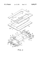
- FIG. 2 is a perspective view of E type sheet cores and a coil bobbin of the embodiment of the present invention
- FIG. 3A is a plan view of the coil bobbin of the embodiment of the present invention
- FIG. 3B is a partially broken side view of the coil bobbin of the embodiment of the present invention
- FIG. 3C is a bottom view of the embodiment of the coil bobbin of the present invention.
- FIG. 4 is a perspective view of a cover of the embodiment of the present invention.
- FIG. 5 is a plan view of the cover of the embodiment of the present invention.
- FIG. 5B is a cross-sectional view of the cover taken along line F--F of FIG. 5A;
- FIG. 5C is a cross-sectional view of the cover taken along line G--G of FIG. 5A.
- an embodiment of a transformer comprises a coil bobbin 1 made of synthetic resin, laminated sheet cores 2 formed by E type sheet cores 2a and 2b made of a plate material having a high permeability such as Permalloy, silicon steel or magnetic amorphous metal, a cover 3 made of synthetic resin and functioning as a fixing member of the laminated sheet cores 2 and a coil 4 wound around the coil bobbin 1.
- the coil bobbin 1 has a winding drum 5 around which the coil 4 is wound. On both ends of the winding drum 5 are integrally formed flanges 6 and terminal fixing portions 7. On the terminal fixing portion 7 of each end of the winding drum 5 are provided external connection terminals 8 and coil end holding terminals 9. The number and the arrangement of both terminals are decided according to the kinds of the transformers which are to be used. Each external connection terminal 8 and the corresponding coil end holding terminal 9 are integrally connected together in the corresponding terminal fixing portion 7.
- the E type sheet cores 2a and 2b have the same shape. As shown in FIG. 1A, the sheet cores 2a and 2b are directed reverse to each other and their middle legs a are inserted alternately into the core hole 10 from both ends thereof in such a way that the cores 2a and 2b are laminated on each other in the core hole 10.
- Each sheet core 2a (2b ) has outer legs b and a root portion c as well as the middle leg a.
- the cover 3 has a top plate portion 11 and core receiving portions 12 which abut against the ends of the laminated sheet cores 2.
- a rectangular opening 11a is formed in the top plate portion 11 so that heat is radiated effectively therefrom.
- On each of the corners of the opening 11a of the cover 3 is integrally formed a downward extending engaging piece 13.
- receiving portions 14 for engageably receiving the engaging pawls 13a are formed in the inner wall (the wall at the side of the winding drum) of each terminal fixing portion 7.
- the E type sheet cores 2a and 2b are laminated by being inserted alternately into the core hole 10 of the coil bobbin 1 around which the coil 4 is wound.
- the cover 3 is pushed downward in a state in which the opening 11a of the cover 3 is fitted on the coil 4 and the flanges 6.
- the inclining surface 13a of each engaging piece 13 abuts against the inner wall of the corresponding terminal fixing portion 7 and the engaging piece 13 is elastically deformed.
- each engaging pawls 13 abut against the corresponding receiving portion 14 of the terminal fixing portion 7, the engaging piece 13 is elastically restored to the original state, and each engaging pawl 13b engages the corresponding receiving portion 14.
- the cover 3 is fixed to the coil bobbin 1. As shown in FIG.
- the laminated sheet cores 2 are inserted into the core hole 10 and the positions in the directions of their total thickness and their width are limited. Since no force is exerted on the laminated sheet cores 2 in the direction of their total thickness (i.e., in the direction in which the cores are laminated), ⁇ is not lowered and magnetic distortion is not produced. Because the laminated sheet cores 2 are prevented from being removed from the cover 3 and the middle legs a of the cores are inserted into the core hole 10, the movements of the laminated sheet cores 2 in all directions are limited and the cores 2 are secured to the coil bobbin 1.
- the conventional transformer requires fourteen laminated cores, but the present invention requires only ten laminated cores 2 in order to obtain a required characteristic. Further, the attachment of the cover 3 to the coil bobbin 1 and the fixing of the laminated sheet cores 2 to the coil bobbin 1 can be performed simultaneously. Thus, the assembling processes of the transformer are reduced and the transformer can be easily assembled.
- the engaging pieces 13 can be formed on the portions which corresponding to the outer walls of the terminal fixing portions 7. Since, however, each engaging piece 13 is required to have a predetermined thickness W1 (see FIG. 1A), it is preferred that the engaging piece 13 be formed on the inner wall of the cover 3 in such a way that the engaging pawl 13a is directed outward.
- the engaging pieces 13a are formed to be directed outward, the projected length W2 of the core receiving portions 12 of the cover 3 from the end faces c of the corresponding terminal/fixing portions 7 can be reduced. As a result, the cover 3 can be made small.
- fixing members may be attached to the terminal fixing portions 7 on both ends of the coil bobbin 1 in order to fix the laminated sheet cores 2 to the coin bobbin 1.
- the fixing member may not be of the type directly secured to the coil bobbin 1 but may be of the type indirectly fixed to the coil bobbin 1 by means of another member. Further, still another member for preventing the laminated sheet cores 2 from being removed from the coil bobbin 1 may be provided between the fixing member and the laminated sheet cores 2.
Landscapes
- Engineering & Computer Science (AREA)
- Power Engineering (AREA)
- Coils Or Transformers For Communication (AREA)
- Storage Of Web-Like Or Filamentary Materials (AREA)
Applications Claiming Priority (2)
| Application Number | Priority Date | Filing Date | Title |
|---|---|---|---|
| JP12097996A JP3821311B2 (ja) | 1996-04-17 | 1996-04-17 | 積層シートコアを有するトランス |
| JP8-120979 | 1996-04-17 |
Publications (1)
| Publication Number | Publication Date |
|---|---|
| US5859577A true US5859577A (en) | 1999-01-12 |
Family
ID=14799785
Family Applications (1)
| Application Number | Title | Priority Date | Filing Date |
|---|---|---|---|
| US08/838,810 Expired - Lifetime US5859577A (en) | 1996-04-17 | 1997-04-10 | Transformer with laminated sheet cores |
Country Status (4)
| Country | Link |
|---|---|
| US (1) | US5859577A (ja) |
| JP (1) | JP3821311B2 (ja) |
| KR (1) | KR100234487B1 (ja) |
| TW (1) | TW323375B (ja) |
Cited By (5)
| Publication number | Priority date | Publication date | Assignee | Title |
|---|---|---|---|---|
| US6078240A (en) * | 1999-05-07 | 2000-06-20 | Huang; Ming Shih | Isolating cover for transformer |
| US6208232B1 (en) * | 1999-02-16 | 2001-03-27 | Atech Technology Co., Ltd. | Dummy pin structure for a miniature transformer |
| US6326874B1 (en) * | 1997-02-24 | 2001-12-04 | Lucent Technologies Inc. | Terminal bobbin for a magnetic device and method of manufacture therefor |
| US20040026123A1 (en) * | 2002-08-09 | 2004-02-12 | Samsung Electronics Co., Ltd. | Apparatus for fixing bobbin to printed circuit board for use in transformer |
| US20170294265A1 (en) * | 2016-04-06 | 2017-10-12 | Sumida Corporation | Small size transformer |
Citations (10)
| Publication number | Priority date | Publication date | Assignee | Title |
|---|---|---|---|---|
| DE144981C (ja) * | ||||
| US4075590A (en) * | 1977-02-22 | 1978-02-21 | Stephen Foldes | Bobbin construction for electrical coils |
| JPS58195405A (ja) * | 1982-05-11 | 1983-11-14 | 富士電機株式会社 | ガス絶縁電気機器の吸着剤取付構造 |
| JPS60133712A (ja) * | 1983-12-22 | 1985-07-16 | Toshiba Corp | 鉄心の固着方法 |
| JPS60202916A (ja) * | 1984-03-28 | 1985-10-14 | Matsushita Electric Ind Co Ltd | フライバツクトランス |
| JPS61168617A (ja) * | 1985-01-21 | 1986-07-30 | Sanyo Kokusaku Pulp Co Ltd | 高純度臭素化エポキシ樹脂の製造法 |
| JPS6473909A (en) * | 1987-09-16 | 1989-03-20 | Daihen Corp | Noise filter |
| US5034854A (en) * | 1989-06-01 | 1991-07-23 | Matsushita Electric Industrial Co., Ltd. | Encased transformer |
| US5264815A (en) * | 1989-05-23 | 1993-11-23 | Tdk Corporation | Fastener for electronic component |
| JPH0722050A (ja) * | 1993-07-05 | 1995-01-24 | Toshiba Corp | 燃料電池発電プラント |
-
1996
- 1996-04-17 JP JP12097996A patent/JP3821311B2/ja not_active Expired - Fee Related
-
1997
- 1997-03-26 TW TW086103837A patent/TW323375B/zh active
- 1997-04-10 US US08/838,810 patent/US5859577A/en not_active Expired - Lifetime
- 1997-04-16 KR KR1019970013964A patent/KR100234487B1/ko not_active Expired - Fee Related
Patent Citations (10)
| Publication number | Priority date | Publication date | Assignee | Title |
|---|---|---|---|---|
| DE144981C (ja) * | ||||
| US4075590A (en) * | 1977-02-22 | 1978-02-21 | Stephen Foldes | Bobbin construction for electrical coils |
| JPS58195405A (ja) * | 1982-05-11 | 1983-11-14 | 富士電機株式会社 | ガス絶縁電気機器の吸着剤取付構造 |
| JPS60133712A (ja) * | 1983-12-22 | 1985-07-16 | Toshiba Corp | 鉄心の固着方法 |
| JPS60202916A (ja) * | 1984-03-28 | 1985-10-14 | Matsushita Electric Ind Co Ltd | フライバツクトランス |
| JPS61168617A (ja) * | 1985-01-21 | 1986-07-30 | Sanyo Kokusaku Pulp Co Ltd | 高純度臭素化エポキシ樹脂の製造法 |
| JPS6473909A (en) * | 1987-09-16 | 1989-03-20 | Daihen Corp | Noise filter |
| US5264815A (en) * | 1989-05-23 | 1993-11-23 | Tdk Corporation | Fastener for electronic component |
| US5034854A (en) * | 1989-06-01 | 1991-07-23 | Matsushita Electric Industrial Co., Ltd. | Encased transformer |
| JPH0722050A (ja) * | 1993-07-05 | 1995-01-24 | Toshiba Corp | 燃料電池発電プラント |
Non-Patent Citations (1)
| Title |
|---|
| IBM Technical Disclosure Bulletin, High Voltage Shield, Chacon et al, vol. 23, No. 1, Jun. 1980, pp. 65, 66. * |
Cited By (8)
| Publication number | Priority date | Publication date | Assignee | Title |
|---|---|---|---|---|
| US6326874B1 (en) * | 1997-02-24 | 2001-12-04 | Lucent Technologies Inc. | Terminal bobbin for a magnetic device and method of manufacture therefor |
| US6208232B1 (en) * | 1999-02-16 | 2001-03-27 | Atech Technology Co., Ltd. | Dummy pin structure for a miniature transformer |
| US6078240A (en) * | 1999-05-07 | 2000-06-20 | Huang; Ming Shih | Isolating cover for transformer |
| US20040026123A1 (en) * | 2002-08-09 | 2004-02-12 | Samsung Electronics Co., Ltd. | Apparatus for fixing bobbin to printed circuit board for use in transformer |
| US7154365B2 (en) * | 2002-08-09 | 2006-12-26 | Samsung Electronics Co., Ltd. | Apparatus for fixing bobbin to printed circuit board for use in transformer |
| US20170294265A1 (en) * | 2016-04-06 | 2017-10-12 | Sumida Corporation | Small size transformer |
| CN107275043A (zh) * | 2016-04-06 | 2017-10-20 | 胜美达集团株式会社 | 小型变压器 |
| US10008321B2 (en) * | 2016-04-06 | 2018-06-26 | Sumida Corporation | Small size transformer |
Also Published As
| Publication number | Publication date |
|---|---|
| JP3821311B2 (ja) | 2006-09-13 |
| JPH09283341A (ja) | 1997-10-31 |
| KR100234487B1 (ko) | 1999-12-15 |
| TW323375B (ja) | 1997-12-21 |
Similar Documents
| Publication | Publication Date | Title |
|---|---|---|
| US6608544B2 (en) | Reactor | |
| US5534839A (en) | Miniature transformer | |
| US20090237196A1 (en) | Method for manufacturing transformer, and transformer | |
| US5859577A (en) | Transformer with laminated sheet cores | |
| EP0399779B1 (en) | An electronic component with a fastener | |
| EP1168386B1 (en) | Coil apparatus and manufacturing method for the same | |
| JP2007123928A (ja) | 変圧器などの磁気組立体 | |
| JPH1167541A (ja) | インダクタ装置 | |
| JPH0799120A (ja) | 面実装型コイル | |
| KR20220000886U (ko) | 슬림형 트랜스포머 | |
| JPH07106147A (ja) | 面実装型インダクタ | |
| JPH07106142A (ja) | トロイダルコイル | |
| JPH07106148A (ja) | 面実装型コイル | |
| JPH082976Y2 (ja) | ラインフィルタ | |
| JP2591347Y2 (ja) | トランス | |
| JPH0124908Y2 (ja) | ||
| JPH07263238A (ja) | インダクタンス素子 | |
| JP2985663B2 (ja) | コイル部品 | |
| JP2503827Y2 (ja) | ラインフィルタ | |
| JP3407522B2 (ja) | コイル部品 | |
| JP2607610Y2 (ja) | トランス | |
| JPH0113393Y2 (ja) | ||
| JPS592165B2 (ja) | 電磁装置 | |
| JPH0124891Y2 (ja) | ||
| JPH0655229U (ja) | インダクタ及びこれに使用されるコアホルダー |
Legal Events
| Date | Code | Title | Description |
|---|---|---|---|
| AS | Assignment |
Owner name: TDK CORPORATION, JAPAN Free format text: ASSIGNMENT OF ASSIGNORS INTEREST;ASSIGNORS:NIHEI, TAKAYUKI;SATO, NORIO;REEL/FRAME:008571/0624 Effective date: 19970324 |
|
| FEPP | Fee payment procedure |
Free format text: PAYOR NUMBER ASSIGNED (ORIGINAL EVENT CODE: ASPN); ENTITY STATUS OF PATENT OWNER: LARGE ENTITY |
|
| STCF | Information on status: patent grant |
Free format text: PATENTED CASE |
|
| FPAY | Fee payment |
Year of fee payment: 4 |
|
| FEPP | Fee payment procedure |
Free format text: PAYER NUMBER DE-ASSIGNED (ORIGINAL EVENT CODE: RMPN); ENTITY STATUS OF PATENT OWNER: LARGE ENTITY Free format text: PAYOR NUMBER ASSIGNED (ORIGINAL EVENT CODE: ASPN); ENTITY STATUS OF PATENT OWNER: LARGE ENTITY |
|
| FPAY | Fee payment |
Year of fee payment: 8 |
|
| FPAY | Fee payment |
Year of fee payment: 12 |