EP0845725B1 - Dispositif servant a commander le deplacement d'un robot vers l'arriere - Google Patents
Dispositif servant a commander le deplacement d'un robot vers l'arriere Download PDFInfo
- Publication number
- EP0845725B1 EP0845725B1 EP97927411A EP97927411A EP0845725B1 EP 0845725 B1 EP0845725 B1 EP 0845725B1 EP 97927411 A EP97927411 A EP 97927411A EP 97927411 A EP97927411 A EP 97927411A EP 0845725 B1 EP0845725 B1 EP 0845725B1
- Authority
- EP
- European Patent Office
- Prior art keywords
- robot
- command
- backward
- data
- backward operation
- Prior art date
- Legal status (The legal status is an assumption and is not a legal conclusion. Google has not performed a legal analysis and makes no representation as to the accuracy of the status listed.)
- Expired - Lifetime
Links
Images


Classifications
-
- G—PHYSICS
- G05—CONTROLLING; REGULATING
- G05B—CONTROL OR REGULATING SYSTEMS IN GENERAL; FUNCTIONAL ELEMENTS OF SUCH SYSTEMS; MONITORING OR TESTING ARRANGEMENTS FOR SUCH SYSTEMS OR ELEMENTS
- G05B19/00—Program-control systems
- G05B19/02—Program-control systems electric
- G05B19/18—Numerical control [NC], i.e. automatically operating machines, in particular machine tools, e.g. in a manufacturing environment, so as to execute positioning, movement or co-ordinated operations by means of program data in numerical form
- G05B19/408—Numerical control [NC], i.e. automatically operating machines, in particular machine tools, e.g. in a manufacturing environment, so as to execute positioning, movement or co-ordinated operations by means of program data in numerical form characterised by data handling or data format, e.g. reading, buffering or conversion of data
-
- G—PHYSICS
- G05—CONTROLLING; REGULATING
- G05B—CONTROL OR REGULATING SYSTEMS IN GENERAL; FUNCTIONAL ELEMENTS OF SUCH SYSTEMS; MONITORING OR TESTING ARRANGEMENTS FOR SUCH SYSTEMS OR ELEMENTS
- G05B2219/00—Program-control systems
- G05B2219/30—Nc systems
- G05B2219/34—Director, elements to supervisory
- G05B2219/34332—Program execution as function of direction, forward or backward
-
- G—PHYSICS
- G05—CONTROLLING; REGULATING
- G05B—CONTROL OR REGULATING SYSTEMS IN GENERAL; FUNCTIONAL ELEMENTS OF SUCH SYSTEMS; MONITORING OR TESTING ARRANGEMENTS FOR SUCH SYSTEMS OR ELEMENTS
- G05B2219/00—Program-control systems
- G05B2219/30—Nc systems
- G05B2219/36—Nc in input of data, input key till input tape
- G05B2219/36558—Forward and backward reading of tape, reverse execution program
Definitions
- the present invention relates to a robot control apparatus, and more particularly, to a robot control having a backward operation function for operating a robot to retrace a history of program execution.
- a robot control apparatus has a function called a backward operation function as one of general functions thereof. This function of control is in a contrast to a forward operation function for operating a robot by reading an operation program forward, and is used for operating a robot to retrace the forward operation.
- the backward operation function is used when it is necessary to return the robot to an intermediate position or an initial position on a taught path so as to confirm the taught path or modify taught positions in a teaching operation, or when it is necessary to retract the robot which has been interfered and stopped in emergency from the interfered position.
- EP-A-0368088 discloses a robot control apparatus having a backward operation function, as set out in the preamble of attached claim 1.
- One object of the present invention is to provide a robot control device with a backward operation function which device also takes account of motions of cooperative devices involving the input/output of external signals, such as an opening/closing motion of a hand or a spot gun.
- Another object of the present invention is to provide a robot control device with a backward operation function whereby, even in the case where a branch command is executed during forward operation, backward operation based on accurate execution history can be performed taking such a branch command into account.
- embodiments of the present invention may provide a robot control device capable of executing a backward mode executable program or command in combination when the backward operation function is activated, and may provide a robot control device permitting the output states of I/O commands to be specified, and to permit a backward operation entailing restoration of register values to be carried out.
- a robot control apparatus for controlling a robot, comprising:
- the backward operation processing means performs processing of operating both the robot and the cooperative device backward so that history of the forward operations of the robot and the cooperative device is traced backward.
- the execution history data may include data indicative of a status of such an external device before the status of the device changes in response to forward operation. Then, based on the data indicative of the status before change, the backward operation processing is performed such that the status of the external device is restored.
- the history data may include data indicative of a computation value before it changes in response to the forward operation, and based on the data indicative of the value before change, the backward operation processing may be performed so that the computation value is restored.
- the history data may include data of the backward operation dedicated command, and during backward operation, the backward operation dedicated command may be executed in accordance with the data of the backward operation dedicated command.
- the history data may include data of the subprogram start command, and during backward operation, the subprogram may be executed in accordance with the data of the subprogram start command.
- one of continuous mode and step mode is selectable for the execution of the backward operation. Also, to secure the safety of the operator, the operator's attention is preferably called when the backward operation is performed.
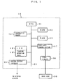
- FIG. 1 shows an arrangement of a principal part of a robot control apparatus according to an embodiment of the present invention in the form of a block diagram.
- a robot control apparatus 10 has a central processing unit (CPU) 11 which are connected to a memory 12 in the form of ROM, a memory 13 in the form of RAM, a nonvolatile memory 14 in the form of a CMOS etc., a teaching operation panel 16 with an LCD (liquid crystal display) 15, a robot axis control section 17 for controlling individual axes of a robot, and a general-purpose signal interface 19 connected to external devices (such as a a conveyor, a workpiece box changer, a spot gun, an alarm lamp, a buzzer and an offline programming device, which are not shown) via a bus 20.
- the robot axis control section 17 is also connected to a robot body 30 via a servo circuit 18.
- the ROM 12 stores various programs to be executed by the CPU 11 to control the robot 30 as well as the robot device 10 itself.
- the RAM 13 is a memory used for temporary storage of data and for computation.
- the nonvolatile memory 14 is used to store various parameter set values and program data manually inputted from the teaching operation panel 16 or inputted by off-line through the interface 19.
- the nonvolatile memory 14 stores program data necessary for performing a backward operation function according to characterizing features of the present invention and has a required buffer area, registers, etc. set therein.
- processes relating to the backward operation function will be outlined and then explained in detail with reference to a specific example of operation program.
- the backward operation function is a function in relation to a forward operation which is performed by reading a program forward, and includes a continuous mode and a stepwise mode as modes for execution.
- the former is a mode in which history data about the forward operation is continuously and automatically read backward to achieve successive backward operation.
- the backward operation function is activated in continuous mode, the backward operation of the robot is continuously performed until the beginning of the history data or the end of a retrace range specified by the operator is reached, unless a command to suspend the execution of backward operation is input or an alarm is output in the middle of the movement.
- the latter is a mode in which the history data is executed backward step by step when receiving a backward operation continuing command from the operator. Accordingly, the backward operation of the robot is not continued unless the command is inputted step by step.
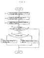
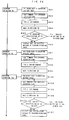
- FIG. 2 is a flowchart schematically showing a flow of operations and processing relating to the backward operation function, taking account of the aforementioned matter as well as execution of a backward mode executable program/command and selective specification of the output states of I/O commands.
- Step S1 the operator specifies and starts a program for the robot as in the case of a normal playback operation, whereupon execution of the program is started (Step S1). Needless to say, the processing executed in this case is a forward operation.
- the motion of the robot is started at the time of an output of a motion command.
- the execution history data written in the memory may include data other than that relating to actually executed commands, as described later referring to a specific example.
- Step S3 After the forward operation according to the program is terminated (Step S3), when the CPU 11 confirms an operator's intention to perform the backward operation ("Yes" in Step S4) based on an operator's manual input or an external signal input, it is determined whether or not the backward operation is to be performed in the continuous mode or the step mode (Step S5), and then a backward operation processing is executed in the continuous or step mode (Step S6 or S7).
- the forward operation may be terminated in Step S3 at an intermediate stage of the forward operation according to the program.
- the position (row) on the program at which the forward operation is terminated may not necessarily be the same as the position (row) on the program from which the backward operation is to be started (for example, the backward operation may be started from a 15th row after execution of the forward operation by 1st to 20th rows). If it is confirmed by the CPU 11 that the operator has no intention of performing backward operation ("No" in Step S4), the processing is of course terminated.
- the program is read line by line and executed.
- execution history data is written in the memory.
- corresponding history data is written without executing such commands during the forward operation.
- a type of the executed command is discriminated and then table data is created in the form of a combination of command-type discriminative data and related history data.
- table data "(*2) execution history table” as shown in FIG. 4 is successively created through execution of the process "(*1) command type check flow” shown in FIG. 3. Symbols (*1), (*2), etc. are used for ease of distinguishment in the drawings and related explanation to follow.
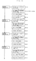
- Steps S15 to S19 are executed depending on the decisions made in Steps S11 to S14. As seen from execution history write rules shown in the figure next to the respective Steps S15 to S19, history data to be written slightly varies depending on the command type dedicated.
- Type 1 (backward mode dedicated command): A command specifying execution only during backward operation. This type of command may, however, be written in a program as a command accompanying a statement which is to be executed during forward operation, as described later (see line 7 of a main program shown in FIG. 7). Namely, the term "backward mode dedicated command” is used herein to signify a "line of command described by such a statement as to include a command which is executed only during backward operation".
- Type 2 Motion command: A Command relating to motion of the robot itself (part driven through a robot axis).
- Type 3 (I/O command): A Command specifying input/output with respect to external devices such as the hand.
- Type 4 (computation command): A Command specifying computation such as increment/decrement of register values.
- Type 5 (other commands): A Command which does not belong to any of Types 1 to 4, such as a branch command.
- Type 1 may be identified by the term "BACKWARD”, Type 2 by “POSITIONING”, “SMOOTH”, etc., Type 3 by “SDI”, “SDO”, etc., Type 4 by “REG”, “COUNT”, etc., and the commands not including these terms may be judged to be Type 5.
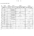
- a buffer for writing the execution history data therein has columns 1 to 5, in which are respectively written the result of command type discrimination, the row number concerned, the position of the robot, the state of I/O signal before execution of the command, and the value of a target of computation command (e.g., register) before execution of the computation command, in accordance with the execution history write rules.
- the figure shows, by way of example, the state in which the writing of data up to row 10 has been completed. The manner of how the execution history data is created will be described later in detail.
- Steps S21 to S24 of the (*3) command type-dependent execution flow can be made immediately based on the column 1 of the read row.
- Steps S25 to S29 processes for the backward operation, outlined below, are executed in accordance with the result of discrimination.
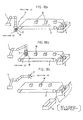
- FIG. 7 a program shown in FIG. 7 is taken as an example. This program is concerned with a task whereby a workpiece fed to a certain position is grasped with the robot hand and placed on a conveyor to be packed in a box. Although an outline of the task is also shown in FIG. 7, a supplementary explanation of the task will be given with reference to the schematic diagrams of FIGS. 18a- 18c.
- a robot 1 is moved from a standby position (not shown) to POSITION [1] (origin position on a motion path) (line 1).
- POSITION [2] oil position on a motion path
- the robot is then moved to POSITION [2] corresponding to a supply position (grasping position) of a workpiece W (line 2), and a hand 2 is closed to thereby grasp the workpiece W (line 3; SDO [1] ON).
- the robot 1 is moved to POSITION [3] which is a placement position above a conveyor 3 (line 4).
- POSITION [3] is a placement position above a conveyor 3 (line 4).
- the hand 2 grasping the workpiece W is then opened to place the workpiece W on the conveyor 3 (line 5; SDO [1] OFF).
- the robot 1, which has completed the placement of the workpiece W on the conveyor 3, is moved to POSITION [4] which is a retraction position (line 6).
- SDO [2] which is a forward travel signal for the conveyor 3, is set ON to cause the conveyor to move forward for a predetermined distance (line 7).
- Line 7 includes a command (parenthesized command) which is to be executed only during backward operation, and thus the command type thereof is categorized as the backward mode dedicated command.
- SDO [2] is set OFF (travel of the conveyor is stopped) in accordance with the parenthesized command, as described later.
- the next line 8 is a backward mode dedicated command which does not include a command to be executed during forward operation, and accordingly, the task does not progress. Further, the register value is incremented by "1" so as to store data that one workpiece W has been conveyed (line 9).
- Line 10 and the following lines are concerned with a process for changing the workpiece box 4 with a new one 4' when the workpiece box 4 is filled with workpieces (in this example, ten workpieces). Specifically, when the register value shows a saturation value of "10", it is judged that the workpiece box 4 is filled. If "10" is not yet reached by the register value, the program jumps to LABEL [1] (line 10, line 13), and the robot 1 is returned to POSITION [1] (line 14).
- a subprogram called only during backward operation by the backward mode dedicated command at line 8 includes a command whereby SDO [4], which is a backward travel signal for the conveyor 3, is set ON, as shown in the lowermost part of FIG. 7, to cause the conveyor to move backward for the predetermined distance. Operations during backward operation including the execution of this command will be described later.
- the part (lines 1 through 14) of the program shown in FIG. 7 except the subprogram is referred to as the main program.
- FIGS. 8 through 12 are flowcharts illustrating a process flow of forward operation according to the main program, together with the status of the execution history data writing.
- the process flow will be hereinafter explained in order.
- the register value of REG [1] (the index value indicative of the number of workpieces contained in the workpiece box) at the start of the processing cycle is "5", by way of example.
- FIG. 8 (FIG. 8)
- the command at line 1 is a robot motion command to move the robot to POSITION [1]. Accordingly, data "TYPE 2", “1", and “POSITION [1]” are written in columns 1 to 3 at the first row of the table, respectively, and columns 4 and 5 are left blank (TB1). Executing the command at this line moves the robot to POSITION [1] (approach position for grasping a workpiece).
- FIG. 9 (FIG. 9)
- the above completes one cycle of forward operation process.
- the task performed includes placing one workpiece W on the conveyor 3, conveying the workpieces W, and putting one workpiece W into the workpiece box 4, as explained with reference to FIGS. 7 and 18a-18c.
- the (*1) execution history table is in the state indicated by TB14.
- the workpiece packing operation progresses as the aforementioned processing cycle is repeated, and if the register value reaches "10" (the workpiece box 4 is filled), the result of decision at Step F103 becomes No when line 10 is executed; in this case, the program makes no jump and lines 11 and 12 are executed, followed by execution of lines 13 and 14.
- FIG. 13 shows the correspondence of the data written in the (*1) execution history table to "backward operation (1)” through “backward operation (12)” indicative of the progress of a backward operation process flow explained hereinafter.
- the backward operation process flow is executed by reading data so as to trace the execution history backward, that is, from the lowermost line upward.
- FIGS. 14 through 17 are flowcharts similar to those of FIGS. 8 to 12, illustrating a process flow according to a program (main program + subprogram) for backward operation in this embodiment.
- the flowcharts will be now explained in order.
- the "backward processing" used in the following explanation is not a narrow term restrictively indicating a process for backward operation of the robot itself, but a generic term representing a process of operations performed by the robot control device during backward operation, and may include the following processes:
- the data read from the execution history table in this case are the data in columns 1 to 3 at the twelfth row. Accordingly, the result of the command type discrimination (B13) is Type 2 (motion command), and a process for moving the robot to POSITION [1] (origin position on the motion path) described in column 3 is performed (B14) as the backward process.
- the data in column 2 is utilized to determine the condition for movement type (linear motion, circular motion, motion of each axis, etc.) and the like.
- An override for the backward operation is set separately.
- For the backward operation in general, an override smaller than that applied to the forward operation is specified (the speed is reduced).
- the data read from the execution history table are the data in columns 1 and 2 at the eleventh row, and thus the result of command type discrimination (B23) is Type 5 (other command). In the backward process, therefore, only advance to the next step is confirmed and no substantial change in the system status occurs (B24).
- the data read from the execution history table in this case are the data in columns 1 and 2 at the tenth row. Accordingly, the result of command type discrimination (B33) is Type 5 (other command), and the system status does not substantially change (B34), as in the case of the backward operation (2).
- the data read from the execution history table are the data in columns 1, 2 and 5 at the ninth row.
- the result of command type discrimination (B43) is Type 4 (computation command).
- the process for restoring the register value of REG[1] to "5" described in column 5 is carried out.
- the data read from the execution history table in this case are the data in columns 1 and 2 at the eighth row, and thus the result of command type discrimination (B53) is Type 1 (backward mode dedicated command).
- the subprogram (see the lower part of FIG. 7) is executed in compliance with the statement at row 8 of the main program, as specified by the data in column 2. Namely, the I/O signal SDO [4] is set ON to move the conveyor 3 backward (B54).
- the data read from the execution history table are the data in columns 1 to 3 at the seventh row.
- the result of command type discrimination (B63) is Type 1 (backward mode dedicated command); however, unlike the case of [Backward Operation (5)], "POSITION [4]" is described in column 3 at the seventh row.
- the robot is first moved to POSITION [4] (retraction position) (B64), and then in accordance with the parenthesized command in the statement at row 7 of the main program as specified by the data in column 2, the I/O signal SDO [2] is set OFF to thereby stop the conveyor 3 (B65).
- the data read from the execution history table in this case are the data in columns 1 to 3 at the sixth row, and thus the result of command type discrimination (B73) is Type 2 (motion command).
- the process for moving the robot to POSITION [4] (retraction position) described in column 3 is executed (B74).
- POSITION [4] retract position
- the data read from the execution history table are the data in columns 1 to 4 at the fifth row, and accordingly, the result of command type discrimination (B83) is Type 3 (I/O command). Since, however, "POSITION [3]" is described in column 3 at the fifth row, first, in the backward process, the robot is moved to POSITION [3] (conveyor placement position).
- the data read from the execution history table are the data in columns 1 to 3 at the fourth row. Accordingly, the result of command type discrimination (B93) is Type 2 (motion command), and in the backward process, the process for moving the robot to POSITION [3] (conveyor placement position) described in column 3 is executed (B94). In this case, however, since the robot has already been moved to POSITION [3] in B84 of the backward operation (8), no actual robot motion takes place.
- the data read from the execution history table in this case are the data in columns 1 to 4 at the third row, and therefore, the result of command type discrimination (B103) is Type 3 (I/O command). Since, however, "POSITION [2]" is described in column 3 at the third row, first, in the backward process, the robot is moved to POSITION [2] (workpiece grasping position).
- the data read from the execution history table are the data in columns 1 to 3 at the second row.
- the result of command type discrimination (B113) is Type 2 (motion command), and the process for moving the robot to POSITION [2] (workpiece grasping position) described in column 3 is executed (B114). Since, however, the robot has already been moved to POSITION [2] in B104 of the backward operation (10), no actual robot motion takes place.
- the data read from the execution history table in this case are the data in columns 1 to 3 at the first row. Accordingly, the result of command type discrimination (B123) is Type 2 (motion command), and in the backward process, the process for moving the robot to POSITION [1] (origin position on the motion path) described in column 3 is executed (B124).
- the robot 1 moves to POSITION [1] (origin position on the motion path). If, however, the robot position at the start of backward operation coincides with POSITION [1], the robot does not move in actuality. Subsequently, the index value indicative of the number of workpieces W conveyed to the workpiece box 4 is decremented by "1", and the conveyor 3 travels backward for the predetermined distance. Consequently, the workpiece W which was previously placed on the conveyor 3 returns to the conveyor placement position.
- POSITION [1] oil position on the motion path
- the robot 1 moves to POSITION [3] (conveyor placement position) via POSITION [4] (retraction position), and closes the hand 2 to grasp the workpiece W.
- POSITION [3] conveyor placement position
- POSITION [4] retract position
- the robot 1 moves to POSITION [2] (grasping position) while grasping the workpiece W, and opens the hand 2 to release the workpiece W.
- the robot 1 which has released the workpiece W, returns to POSITION [1] (origin position on the motion path). This operation is achieved by the backward operation (12) explained above.
- the backward operation function when the backward operation function is activated in continuous mode, the above-described backward operations are continuously executed.
- the backward operation function By activating the backward operation function in step mode, it is possible to perform the backward operations intermittently. It is preferable that only a simple key-in operation of the teaching panel 16 be required to select the continuous mode or the step mode and to perform backward operations step by step when the step mode is selected.
- the function of a SINGLE STEP key may be designed such that depressing the SINGLE STEP key once selects the step mode, and that depressing the SINGLE STEP key one more time returns the mode selection to the continuous mode.
- the aforementioned backward operations (1) to (12) may be performed in order one at a time each time a BWD key is depressed with a SHIFT key held down.
- the inversion specification of I/O signals is set “valid", but depending on the task type and circumstances, the inversion specification may be set "invalid" so that the operator can individually specify the I/O signal states (i.e., states of the hand etc.) during backward operations.
- an alarm signal is output to the LCD 15 associated with the teaching panel, an alarm lamp, a buzzer, etc. connected to the general-purpose interface 19, to call the operator's attention and thereby secure the safety of the operator.
- the present invention remarkably expands the backward operation function of the robot control device and enhances the usefulness to the operator.
- the backward operation can be performed as desired while permitting optional settings of various operations other than the motions of the robot itself (motion involving the input/output of an external signal such as opening/closing of the hand or the spot gun, computation such as addition or subtraction of the register value, etc.).
- motion involving the input/output of an external signal such as opening/closing of the hand or the spot gun, computation such as addition or subtraction of the register value, etc.
- backward operation based on correct execution history can be achieved, taking the branch command into account.
- the backward mode executable program or command can also be executed in combination.
Landscapes
- Engineering & Computer Science (AREA)
- Human Computer Interaction (AREA)
- Manufacturing & Machinery (AREA)
- Physics & Mathematics (AREA)
- General Physics & Mathematics (AREA)
- Automation & Control Theory (AREA)
- Numerical Control (AREA)
- Manipulator (AREA)
Claims (10)
- Dispositif de commande de robot (10) pour commander un robot (1), comprenant :un premier moyen de stockage (12) pour stocker un programme de fonctionnement incluant au moins une instruction pour spécifier un fonctionnement dudit robot (1) ;un moyen de traitement d'opération vers l'avant (11) pour exécuter le traitement de fonctionnement dudit robot (1) vers l'avant en accord avec ledit programme de fonctionnement ;un deuxième moyen de stockage (14) pour stocker des données d'histoire des opérations vers l'avant dudit robot (1) lorsque ledit traitement d'opération vers l'avant est exécuté ; etun moyen de traitement de fonctionnement vers l'arrière (11) pour exécuter le traitement de fonctionnement du robot (1) vers l'arrière de sorte que l'histoire de l'opération vers l'avant dudit robot (1) est retracée sur la base desdites données d'histoire stockées dans ledit deuxième moyen de stockage (14) ;caractérisé en ce que :le dispositif de commande de robot (10) est également réalisé pour commander un dispositif de coopération fonctionnant mécaniquement (2, 3, 4) pour l'opération avec le robot (1) afin d'exécuter une opération mécanique utile en coopération avec le robot (1) ;ledit programme de fonctionnement comprend en outre au moins une instruction pour spécifier un fonctionnement dudit dispositif de coopération (2, 3, 4) ;ledit moyen de traitement de fonctionnement vers l'avant (11) est également réalisé pour exécuter le traitement dudit dispositif de coopération (2, 3, 4) vers l'avant en accord avec ledit programme de fonctionnement ;ledit deuxième moyen de stockage (14) est également réalisé pour stocker des données d'histoire des fonctionnements vers l'avant dudit dispositif de coopération (2, 3, 4) lorsque ledit traitement de fonctionnement vers l'avant est exécuté, ensemble avec des données définissant les types de commande réalisés par lesdites instructions dans le programme de fonctionnement à la fois du robot (1) et du dispositif de coopération (2, 3, 4) ; etledit moyen de traitement de fonctionnement vers l'arrière (11) est réalisé pour exécuter le traitement de fonctionnement à la fois dudit robot (1) et dudit dispositif de coopération (2, 3, 4) vers l'arrière de sorte que l'histoire des opérations vers l'avant à la fois dudit robot et dudit dispositif de coopération (2, 3, 4) est retracée sur la base desdites données d'histoire stockées dans ledit deuxième moyen de stockage (14), et en outre sur la base des résultats de distinction des types de commande réalisés par lesdites instructions dans le programme de fonctionnement de telle sorte que le fonctionnement vers l'arrière est atteint non pas uniquement en retraçant les données d'histoire stockées du fonctionnement vers l'avant du robot (1) et du dispositif de coopération (2, 3, 4).
- Dispositif de commande de robot selon la revendication 1, où au moins une instruction précitée pour spécifier le fonctionnement dudit dispositif de coopération (2, 3, 4) comprend une commande d'entrée/sortie se rapportant à une entrée/sortie d'un signal pour déterminer un état dudit dispositif de coopération (2, 3, 4), lesdites données d'histoire comprennent des données indiquant l'état dudit dispositif de coopération (2, 3, 4) avant que l'état ne change en réponse à la commande d'entrée/sortie pendant ladite opération vers l'avant, et
ledit moyen de traitement de fonctionnement vers l'arrière (11) exécute ledit traitement de fonctionnement vers l'arrière sur la base des données indiquant l'état avant un changement de sorte que l'état dudit dispositif de coopération (2, 3, 4) est restauré. - Dispositif de commande de robot selon la revendication 2, comprenant en outre un moyen pour invalider sélectivement la restauration de l'état dudit dispositif de coopération (2, 3, 4) pendant ledit traitement de fonctionnement vers l'arrière.
- Dispositif de commande de robot selon la revendication 1, où au moins une instruction précitée pour spécifier le fonctionnement dudit dispositif de coopération (2, 3, 4) comprend une commande d'entrée/sortie se rapportant à une entrée/sortie d'un signal pour déterminer un état ouvert/fermé d'une main de robot (2), lesdites données d'histoire comprennent des données indiquant l'état ouvert/fermé de ladite main de robot (2) avant que l'état ne change en réponse à la commande d'entrée/sortie pendant ledit fonctionnement vers l'avant, et
ledit moyen de traitement de fonctionnement vers l'arrière (11) exécute le traitement de fonctionnement vers l'arrière sur la base des données indiquant l'état avant le changement de sorte que l'état ouvert/fermé de ladite main de robot (2) est restauré. - Dispositif de commande de robot selon la revendication 4, comprenant en outre un moyen pour invalider sélectivement la restauration de l'état ouvert/fermé de ladite main de robot (2) pendant ledit traitement de fonctionnement vers l'arrière.
- Dispositif de commande de robot selon la revendication 1, où au moins une instruction précitée pour spécifier le fonctionnement dudit dispositif de coopération (2, 3, 4) comprend une commande de calcul, lesdites données d'histoire comprennent des données indiquant une valeur de calcul avant que la valeur ne change en réponse à la commande de calcul pendant ladite opération vers l'avant et,
ledit moyen de traitement de fonctionnement vers l'arrière (11) exécute le traitement de fonctionnement vers l'arrière sur la base des données indiquant la valeur de calcul avant le changement de sorte que la valeur de calcul est restaurée. - Dispositif de commande de robot selon l'une des revendications précédentes, où ledit programme de fonctionnement comprend une commande dédiée au fonctionnement vers l'arrière destiné à être exécuté seulement pendant le fonctionnement vers l'arrière lesdites données d'histoire comprennent des données de ladite commande dédiée au fonctionnement vers l'arrière, et,
ledit moyen de traitement de fonctionnement vers l'arrière (11) exécute ladite commande dédiée au fonctionnement vers l'arrière en accord avec les données de ladite commande dédiée au fonctionnement vers l'arrière. - Dispositif de commande de robot selon l'une des revendications précédentes, où ledit programme de fonctionnement comprend une commande de démarrage pour démarrer un sous-programme qui comprend une commande dédiée au fonctionnement vers l'arrière destinée à être exécutée seulement pendant le fonctionnement vers l'arrière, lesdites données d'histoire comprennent des données de ladite commande de démarrage de sous-programme, et
ledit moyen de traitement de fonctionnement vers l'arrière (11) exécute ledit sous-programme en accord avec les données de ladite commande de démarrage de sous-programme. - Dispositif de commande de robot selon l'une des revendications précédentes, comprenant en outre un moyen pour régler sélectivement l'un parmi un mode continu et un mode par paliers pour ledit fonctionnement vers l'arrière.
- Dispositif de commande de robot selon l'une des revendications précédentes, comprenant en outre un moyen pour attirer l'attention d'un opérateur pendant ledit fonctionnement vers l'arrière.
Applications Claiming Priority (3)
| Application Number | Priority Date | Filing Date | Title |
|---|---|---|---|
| JP8178691A JPH1011124A (ja) | 1996-06-20 | 1996-06-20 | ロボットの後退実行機能を備えたロボット制御装置 |
| JP178691/96 | 1996-06-20 | ||
| PCT/JP1997/002137 WO1997049016A1 (fr) | 1996-06-20 | 1997-06-20 | Dispositif servant a commander le deplacement d'un robot vers l'arriere |
Publications (3)
| Publication Number | Publication Date |
|---|---|
| EP0845725A1 EP0845725A1 (fr) | 1998-06-03 |
| EP0845725A4 EP0845725A4 (fr) | 1998-09-30 |
| EP0845725B1 true EP0845725B1 (fr) | 2006-09-27 |
Family
ID=16052870
Family Applications (1)
| Application Number | Title | Priority Date | Filing Date |
|---|---|---|---|
| EP97927411A Expired - Lifetime EP0845725B1 (fr) | 1996-06-20 | 1997-06-20 | Dispositif servant a commander le deplacement d'un robot vers l'arriere |
Country Status (5)
| Country | Link |
|---|---|
| US (1) | US6285921B1 (fr) |
| EP (1) | EP0845725B1 (fr) |
| JP (1) | JPH1011124A (fr) |
| DE (1) | DE69736733T2 (fr) |
| WO (1) | WO1997049016A1 (fr) |
Families Citing this family (9)
| Publication number | Priority date | Publication date | Assignee | Title |
|---|---|---|---|---|
| JP2005515903A (ja) * | 2001-11-28 | 2005-06-02 | エヴォリューション ロボティクス インコーポレイテッド | ロボット用センサおよびアクチュエータのハードウェア抽象化層内における抽象化および集合化 |
| EP2581409A1 (fr) | 2011-10-11 | 2013-04-17 | Lanxess Deutschland GmbH | Compositions vulcanisables à base de caoutchoucs nitriles contenant des groupes époxy |
| DE102012008073A1 (de) * | 2012-04-24 | 2013-10-24 | Kuka Roboter Gmbh | Verfahren und Mittel zum Vorgeben und/oder Steuern eines Manipulatorprozesses |
| JP6129548B2 (ja) * | 2012-12-21 | 2017-05-17 | セイコーインスツル株式会社 | フェルール分類装置、フェルール分類方法、フェルール分類プログラム、及び記録媒体 |
| DE102014213262A1 (de) * | 2014-07-08 | 2016-01-14 | Kuka Roboter Gmbh | Maschine und Verfahren zum Betreiben einer Maschine |
| EP3722053B1 (fr) * | 2017-12-08 | 2025-04-30 | Fuji Corporation | Dispositif de commande, dispositif d'opération sur pièce à usiner, système d'opération sur pièce à usiner et procédé de commande |
| CN116507457A (zh) * | 2020-09-11 | 2023-07-28 | 发那科株式会社 | 机器人系统及机器人动作的方法 |
| JP7691507B2 (ja) * | 2021-09-07 | 2025-06-11 | ファナック株式会社 | インタロック機能を有する制御装置及び制御方法 |
| US12576525B2 (en) | 2021-09-27 | 2026-03-17 | Fanuc Corporation | Robot system |
Family Cites Families (23)
| Publication number | Priority date | Publication date | Assignee | Title |
|---|---|---|---|---|
| JPS60160411A (ja) * | 1984-02-01 | 1985-08-22 | Nec Corp | ロボツト制御装置 |
| JPH0797288B2 (ja) * | 1984-03-22 | 1995-10-18 | 株式会社東芝 | 多関節マニピユレ−タの制御方法 |
| JPH0693208B2 (ja) * | 1987-02-04 | 1994-11-16 | フアナツク株式会社 | サーボ遅れ補正方法 |
| JP2584225B2 (ja) * | 1987-04-08 | 1997-02-26 | フアナツク株式会社 | 数値制御装置 |
| JPS63256381A (ja) * | 1987-04-10 | 1988-10-24 | フアナツク株式会社 | ロボツト制御装置 |
| JPH0191905A (ja) | 1987-10-02 | 1989-04-11 | Kobe Steel Ltd | 板圧延における板厚制御方法 |
| JP2556963Y2 (ja) * | 1987-12-10 | 1997-12-08 | 三菱電機株式会社 | 数値制御装置 |
| JPH0222708A (ja) * | 1988-07-12 | 1990-01-25 | Yaskawa Electric Mfg Co Ltd | Nc装置およびnc加工プログラムの実行方法 |
| EP0368088B1 (fr) * | 1988-11-11 | 1995-02-15 | Siemens Aktiengesellschaft | Système pour faire fonctionner un robot industriel |
| IT1227718B (it) * | 1988-12-22 | 1991-05-06 | Salvagnini Trasferica S P A Or | Stazione di montaggio e smontaggio a ciclo automatico programmabile ripetitivo per attrezzature di bloccaggio di pezzi su pallet di sostegno |
| JP2815606B2 (ja) * | 1989-04-25 | 1998-10-27 | 株式会社トキメック | コンクリート床仕上ロボットの制御方式 |
| JP2921903B2 (ja) * | 1990-03-02 | 1999-07-19 | 株式会社日立製作所 | 溶接ロボット制御装置 |
| JPH0417002A (ja) * | 1990-05-10 | 1992-01-21 | Fanuc Ltd | シーケンス・プログラムのサーチ方式 |
| JPH04167103A (ja) * | 1990-10-31 | 1992-06-15 | Mitsubishi Electric Corp | プログラムの実行方法および装置 |
| ATE166170T1 (de) * | 1991-07-10 | 1998-05-15 | Samsung Electronics Co Ltd | Bewegliche überwachungsvorrichtung |
| JP2880590B2 (ja) * | 1991-07-24 | 1999-04-12 | 株式会社不二越 | 産業用ロボットの同期制御方法 |
| JPH05165513A (ja) * | 1991-12-17 | 1993-07-02 | Mutoh Ind Ltd | リバース処理方式 |
| US5331264A (en) * | 1993-04-15 | 1994-07-19 | Fanuc Robotics North America, Inc. | Method and device for generating an input command for a motion control system |
| JPH06318110A (ja) * | 1993-05-07 | 1994-11-15 | Fanuc Ltd | Mmcユニット |
| JPH07104817A (ja) * | 1993-09-30 | 1995-04-21 | Toyoda Mach Works Ltd | ロボットの動作軌跡確認装置 |
| JPH07104856A (ja) * | 1993-10-01 | 1995-04-21 | Fanuc Ltd | 振動制御方法 |
| SE9401012L (sv) | 1994-03-25 | 1995-09-26 | Asea Brown Boveri | Robotstyrsystem |
| JP3537229B2 (ja) * | 1995-07-28 | 2004-06-14 | ファナック株式会社 | ロボットの制御方法 |
-
1996
- 1996-06-20 JP JP8178691A patent/JPH1011124A/ja active Pending
-
1997
- 1997-06-20 EP EP97927411A patent/EP0845725B1/fr not_active Expired - Lifetime
- 1997-06-20 DE DE69736733T patent/DE69736733T2/de not_active Expired - Fee Related
- 1997-06-20 WO PCT/JP1997/002137 patent/WO1997049016A1/fr not_active Ceased
- 1997-06-20 US US09/011,963 patent/US6285921B1/en not_active Expired - Fee Related
Also Published As
| Publication number | Publication date |
|---|---|
| JPH1011124A (ja) | 1998-01-16 |
| EP0845725A4 (fr) | 1998-09-30 |
| EP0845725A1 (fr) | 1998-06-03 |
| DE69736733D1 (de) | 2006-11-09 |
| US6285921B1 (en) | 2001-09-04 |
| DE69736733T2 (de) | 2007-02-15 |
| WO1997049016A1 (fr) | 1997-12-24 |
Similar Documents
| Publication | Publication Date | Title |
|---|---|---|
| EP0845725B1 (fr) | Dispositif servant a commander le deplacement d'un robot vers l'arriere | |
| US4409650A (en) | Automatic position controlling apparatus | |
| CN101526812B (zh) | 控制5轴加工装置的数值控制装置 | |
| JP2003303005A (ja) | 数値制御装置 | |
| WO1992008574A1 (fr) | Dispositif commande numeriquement a fonction de simulation d'usinage | |
| JPH02155004A (ja) | 加工プログラム修正方法 | |
| US5808434A (en) | Numerical control apparatus | |
| KR960001291B1 (ko) | 수치 제어 장치 | |
| WO1992011590A1 (fr) | Procede d'instructions pour programme de fonctionnement de robot | |
| JPH0563749U (ja) | 加工時間算出機能を有する数値制御装置 | |
| JP2875941B2 (ja) | ロボットプログラム作成支援システム | |
| JP7088820B2 (ja) | 数値制御装置 | |
| WO1995000890A1 (fr) | Procede d'enseignement d'une position a un robot et appareil de commande | |
| JPH06100931B2 (ja) | 産業用ロボットの制御情報作成装置における変更プログラム作成方法 | |
| JPH05297925A (ja) | 対話形数値制御装置 | |
| JPH04114208A (ja) | Ncプログラムのアニメ描画方法 | |
| WO1993015449A1 (fr) | Procede d'affichage sur ecran pour commande numerique par ordinateur | |
| JPS62204310A (ja) | 加工プログラムの編集方式 | |
| JPH02252004A (ja) | 工具形状描画方式 | |
| JPH06270082A (ja) | 補軸を有するロボットの制御方法 | |
| Prasad | Designing programming station software for CNC profile cutting | |
| JPS6359604A (ja) | 数値制御装置の加工径路変更方法 | |
| JPH0641031B2 (ja) | 溶接ロボットの溶接方法 | |
| JPH0314105A (ja) | 数値制御装置の再順行方法 | |
| JPH06309026A (ja) | プログラマブル・コントローラ用手動操作教示装置 |
Legal Events
| Date | Code | Title | Description |
|---|---|---|---|
| PUAI | Public reference made under article 153(3) epc to a published international application that has entered the european phase |
Free format text: ORIGINAL CODE: 0009012 |
|
| 17P | Request for examination filed |
Effective date: 19980312 |
|
| AK | Designated contracting states |
Kind code of ref document: A1 Designated state(s): DE |
|
| A4 | Supplementary search report drawn up and despatched | ||
| AK | Designated contracting states |
Kind code of ref document: A4 Designated state(s): DE |
|
| 17Q | First examination report despatched |
Effective date: 20000407 |
|
| RAP1 | Party data changed (applicant data changed or rights of an application transferred) |
Owner name: FANUC LTD |
|
| GRAP | Despatch of communication of intention to grant a patent |
Free format text: ORIGINAL CODE: EPIDOSNIGR1 |
|
| GRAS | Grant fee paid |
Free format text: ORIGINAL CODE: EPIDOSNIGR3 |
|
| GRAA | (expected) grant |
Free format text: ORIGINAL CODE: 0009210 |
|
| AK | Designated contracting states |
Kind code of ref document: B1 Designated state(s): DE |
|
| REF | Corresponds to: |
Ref document number: 69736733 Country of ref document: DE Date of ref document: 20061109 Kind code of ref document: P |
|
| PLBE | No opposition filed within time limit |
Free format text: ORIGINAL CODE: 0009261 |
|
| STAA | Information on the status of an ep patent application or granted ep patent |
Free format text: STATUS: NO OPPOSITION FILED WITHIN TIME LIMIT |
|
| 26N | No opposition filed |
Effective date: 20070628 |
|
| PGFP | Annual fee paid to national office [announced via postgrant information from national office to epo] |
Ref country code: DE Payment date: 20090619 Year of fee payment: 13 |
|
| PG25 | Lapsed in a contracting state [announced via postgrant information from national office to epo] |
Ref country code: DE Free format text: LAPSE BECAUSE OF NON-PAYMENT OF DUE FEES Effective date: 20110101 |