EP0562994A2 - Verfahren und Gerät zur Reinigung von Platten - Google Patents
Verfahren und Gerät zur Reinigung von Platten Download PDFInfo
- Publication number
- EP0562994A2 EP0562994A2 EP93480011A EP93480011A EP0562994A2 EP 0562994 A2 EP0562994 A2 EP 0562994A2 EP 93480011 A EP93480011 A EP 93480011A EP 93480011 A EP93480011 A EP 93480011A EP 0562994 A2 EP0562994 A2 EP 0562994A2
- Authority
- EP
- European Patent Office
- Prior art keywords
- disk
- slider
- storage device
- data storage
- outer diameter
- Prior art date
- Legal status (The legal status is an assumption and is not a legal conclusion. Google has not performed a legal analysis and makes no representation as to the accuracy of the status listed.)
- Ceased
Links
Images




Classifications
-
- G—PHYSICS
- G11—INFORMATION STORAGE
- G11B—INFORMATION STORAGE BASED ON RELATIVE MOVEMENT BETWEEN RECORD CARRIER AND TRANSDUCER
- G11B33/00—Constructional parts, details or accessories not provided for in the other groups of this subclass
- G11B33/14—Reducing influence of physical parameters, e.g. temperature change, moisture, dust
- G11B33/1446—Reducing contamination, e.g. by dust, debris
-
- G—PHYSICS
- G11—INFORMATION STORAGE
- G11B—INFORMATION STORAGE BASED ON RELATIVE MOVEMENT BETWEEN RECORD CARRIER AND TRANSDUCER
- G11B23/00—Record carriers not specific to the method of recording or reproducing; Accessories, e.g. containers, specially adapted for co-operation with the recording or reproducing apparatus ; Intermediate mediums; Apparatus or processes specially adapted for their manufacture
- G11B23/50—Reconditioning of record carriers; Cleaning of record carriers ; Carrying-off electrostatic charges
-
- G—PHYSICS
- G11—INFORMATION STORAGE
- G11B—INFORMATION STORAGE BASED ON RELATIVE MOVEMENT BETWEEN RECORD CARRIER AND TRANSDUCER
- G11B23/00—Record carriers not specific to the method of recording or reproducing; Accessories, e.g. containers, specially adapted for co-operation with the recording or reproducing apparatus ; Intermediate mediums; Apparatus or processes specially adapted for their manufacture
- G11B23/50—Reconditioning of record carriers; Cleaning of record carriers ; Carrying-off electrostatic charges
- G11B23/505—Reconditioning of record carriers; Cleaning of record carriers ; Carrying-off electrostatic charges of disk carriers
-
- G—PHYSICS
- G11—INFORMATION STORAGE
- G11B—INFORMATION STORAGE BASED ON RELATIVE MOVEMENT BETWEEN RECORD CARRIER AND TRANSDUCER
- G11B25/00—Apparatus characterised by the shape of record carrier employed but not specific to the method of recording or reproducing, e.g. dictating apparatus; Combinations of such apparatus
- G11B25/04—Apparatus characterised by the shape of record carrier employed but not specific to the method of recording or reproducing, e.g. dictating apparatus; Combinations of such apparatus using flat record carriers, e.g. disc, card
- G11B25/043—Apparatus characterised by the shape of record carrier employed but not specific to the method of recording or reproducing, e.g. dictating apparatus; Combinations of such apparatus using flat record carriers, e.g. disc, card using rotating discs
Definitions
- the present invention relates to disk drive devices, and in particular to a method and apparatus for cleaning disks with a slider.
- a disk drive commonly referred to as a direct access storage device, has one or more disks for storing data.
- the disks are somewhat analogous to a 45 rpm records used on a record player, or compact disks which are used in a CD player in that they are both round, and hold data.
- multiple disks are mounted to a spindle, and spaced apart so that they do not touch each other.
- disks range from 48 millimeters (1.8 inches) to 130 millimeters (5.25 inches) in diameter.
- each disk is smooth and uniform in appearance.
- Data on the disks in a disk drive is not stored in grooves, but in tracks.
- Each disk surface has a number of data tracks situated in concentric circles.
- the tracks on the disk essentially replace the grooves in a 45 rpm record.
- Each track in a disk drive is further subdivided into a number of sectors which is just one portion of the circumferential track.
- Disks in a disk drive are made of a variety of materials.
- the substrate has been made of glass, plastic or metal.
- a magnetizable layer of metal is placed on the substrate or inner core.
- Data is stored on such a disk by magnetizing small portions of the magnetizable layer of the disk.
- the portions magnetized will be in one or more of the sectors mentioned above.
- the data is usually transformed or encoded into a more compact form before it is recorded on the disk. Each portion so magnetized can be thought of as representing either a one or zero.
- a small ceramic block called a slider, containing an electromagnetic transducer, known as a read/write head is passed over the surface of the disk, following the tracks. More specifically, the read/write head is flown at a height of approximately 0.15 micrometers (six millionths of an inch) or less from the surface of the disk. During flight, over the disk surface, the read/write head is energized to various states, causing a domain within a sector in the track below it to be magnetized.
- the read/write head is flown over the disk again. This time, the small magnetized domains of the disk induce a current in the read/write head transducer. By detecting the current from the read/write head, and decoding multiple occurrences from many domains, the data is reconstructed and then used by the computer system.
- both sides of a disk are generally used to store data or other information necessary for the operation of the disk drive. Since the disks are held in a stack and are spaced apart from one another, both the top and the bottom surface of each disk in the stack of disks has its own read/write head. Sometimes, a disk surface is dedicated to containing servo information. Servo information is made up of magnetized portions of the disk that contain information about the position of the head on the disk. Such servo information from one disk can help in determining where the heads on all the other disks are located. Further help may be provided by including some servo information in each sector on the disks.
- the ceramic material comprising the slider, and the head which the slider supports are moved over the surface of the disk using an actuator arm.
- the actuator arms for multiple heads look like a comb, each tooth of the comb extending between the disks, and holding a head adjacent a disk surface containing data.
- a motor coupled to the comb that is referred to as an E block rotates the E block about its spine, causing the heads to move in a direction radial to the disks. The motor is controlled based on feedback from the servo information and with knowledge of where the desired data is physically located on the disk.
- the slider is aerodynamically designed to fly close to the disk surface. Some sliders are subjected to a physical force or bias toward the disk surface by the actuator arm while others may be reverse biased, so that they actually tend to move away from the disk surface. When the disk starts to rotate, the aerodynamic effect causes the slider to fly. Fluid next to the disk, be it air, or a lubricant, provides a cushion, which causes some sliders to be lifted up from the surface of the disk when the disk reaches a desired rotational velocity. In the case of a reverse biased slider, the pressure becomes less between the disk and the slider, causing the slider to move closer to the disk. In either case, the fly height of the slider is very small as previously stated.
- Fibers contacting the disk surface were used in US-A-No. 3,366,390 issued to Applequist et al. to dislodge dust particles. Air flow from the rotating disks then carries the particles off of the disks.
- Removal of debris from a disk surface of a disk drive device is accomplished by rotating the disk towards the back end of a slider. The slider is then moved incrementally radially outward and essentially removes debris from the disk.
- the slider also serves to support a read/write head above the disk surface for reading and writing information on the disk surface.
- a front end of the slider is tapered in a direction away from the surface to provide an aerodynamic structure that is capable of generating lift.
- the disk is rotated into the front end of the slider, and the taper helps the slider to fly above the disk at a desired height.
- the back end of the slider rises fairly normal to the plane of the disk surface, which enables it to act like a debris plow. When the disk is moved toward the back end of the slider, debris is collected at the back surface.
- the backwards sweeping operation is started as soon as power is supplied to the motor to start the disk rotating backwards from normal operation.
- the outwards sweep is completed prior to the disk reaching full rotational speed. While normal rotational velocities are greater than 5000 rotations per minute, the backwards sweep operation completes prior to the velocity reaching 1000 rotations per minute. This relatively low speed prevents the head from attaining lift off velocity during the sweep and ensures that minimal debris is trapped under the slider.
- One advantage of the present invention is that the debris is first swept off the disk prior to running the disk in the normal direction, and possibly smearing or damaging the disk surface or head. By slowly sweeping outward, most of the debris accumulation occurs on the portion of the back of the slider closest to the outer edge of the disk. This helps keep the debris away from the head, which is usually more centrally located at the back of the slider.
- the sweep is done every 500 start stop cycles, or after 1000 hours of continuous operation of the disk drive. In yet a further embodiment, the sweep is done when data error rates reach an undesirable threshold.
- the disk sweeping operation is also useful with portable type disk drives which are designed to plug into computer systems, and be carried away, perhaps to a different computer system.
- Removable disk drives may be subject to more shock and vibration than most disk drives which were designed for use in a fairly stable computer system.
- the added shock and vibration can cause debris trapped inside the disk container to be redeposited on the disk surface. Such debris is easily removed by the sweeping operation.
- Disk drives are also finding their way into applications outside the normal desk top computer configuration, such as laptop computers. As they move into copiers and automobiles, they too will be subject to more vibration and shock, and thus may avail themselves of the present disk sweeping invention.
- Fig. 1 is an exploded view of a disk drive device.
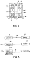
- Fig. 2 is a detailed view of a spindle and spindle motor assembly for the disk drive of Fig. 1.
- Fig. 3 is a block diagram of a spindle motor controller.
- Fig. 4 is a perspective view of a disk slider.
- Fig. 5 is a bottom view of the disk slider of Fig. 4.
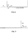
- Fig. 6 is a block diagram side view of the front end of a disk slider.
- Fig. 7 is a block diagram side view of the back end of a disk slider.
- Fig. 8 is a perspective view of a disk slider.
- Fig. 9 is a bottom view of the disk slider of Fig. 8.
- Fig. 10 is a top view of a disk and actuator.
- Fig. 11 is a block diagram of an actuator motor controller.
- Fig. 1 is an exploded view of a disk drive, indicated generally at 10.
- Disk drive 10 includes a housing 12, and a housing cover 14 which, after assembly is mounted within a frame 16.
- the housing 12 and housing cover 14 form a disk drive enclosure.
- Rotatably attached within the housing 12 on an actuator shaft 18 is an actuator arm assembly 20.
- the actuator arm assembly 20 includes an E block 22, which is a comb like structure having a plurality of arms 23. Attached to the separate arms 23 on the E block 22, are load springs 24, commonly referred to as suspensions. Attached at the end of each load spring is a slider 26 which carries read/write elements (not shown in Fig. 1).
- a voice coil 28 is On the other end of the actuator arm assembly 20 opposite the load springs 24 and the sliders 26 a voice coil 28.
- a pair of magnets 30 Attached within the housing 12 is a pair of magnets 30.
- the pair of magnets 30 and the voice coil 28 are key parts of a voice coil motor which applies a force to the actuator assembly 20 to rotate it about the actuator shaft 28.
- a spindle shaft 32 Also mounted within the housing 12 is a spindle shaft 32.
- a hub assembly 33 is rotatably attached to the spindle shaft 32.
- the spindle assembly 31 includes the spindle shaft 32 and the hub assembly 33.
- eight disks 34 are attached to the hub assembly 33. As shown in Fig. 1, disks 34 are attached to the hub assembly 33 with substantially equal spacing between each disk.
- the hub assembly 33 includes a hub 40, hub magnets 42, a first bearing set 44, a second bearing set 46, a mechanical seal 48 and a magnetic fluid seal 50.
- a stator 52 Attached to the spindle shaft 32 is a stator 52 which is a set of coils through which electrical current passes.
- the stator 52 on the spindle shaft 32 and the hub magnets 42 attached to the inside of the hub 40 form an in hub electrical motor which is used to rotate the hub 40 and the disks 34 which are attached to the hub. Electrical energy is input to the stator so that the polarity of the stator is constantly changing and rotating.
- the hub magnets 42 on the hub 40 follow the changing polarity.
- the in-hub motor rotates in excess of 3500 revolutions per minute.
- the coils in stator 52 are arranged in pairs, each pair corresponding to a hub magnet.
- electrical energy is applied to each pair of stator coils in a well known manner.
- the application of energy is alternated between the two magnets of each pair so that the hub magnets 42 are all attracted in the same direction. Initially, half the time the direction is backwards from the normal read/write direction. This is usually detected, as by use of a Hall sensor indicated at 53. If the direction is opposite that intended, the energy is redirected to the other coil in the pairs of coils to reverse the direction of rotation.
- direction detection techniques are used in various disk drives, including the sensing of the spindle motor current referred to as back emf detection as well as the use of the Hall sensor.
- the direction of rotation is usually detected very quickly, within a few pulses of electrical energy to the coils.
- a block diagram of the circuit is shown in Fig. 3.
- a sensor 60 which corresponds to sensor 53 in Fig. 2, detects the direction of rotation of the disks.
- Sensor 60 provides a signal representative of the direction of the rotation of the disks to a processor 62 via a signal converter 64 by lines 66 and 68 respectively.
- Lines 66 and 68, as well as other lines depicted in other electrical diagrams in this specification comprise the appropriate type of communication medium, such as a parallel or serial electrically conductive wire, or wires, or optically conductive lines.
- Converter 64 operates to change the signal from sensor 60 to one understood by processor 62, such as a digital representation of the direction of rotation. In some embodiments, it also provides velocity of rotation information.
- Processor 62 may be any standard type of microprocessor such as one from the Motorolla 68000 family. It is coupled to a memory 70 which stores programs for control of the current supplied to stator 52. Other programs include those which control the positioning of sliders and the actual reading and writing of data on the disk surfaces. Processor 62 controls a current generator/amplifier 72 via line 74. Amplifier 72 provides current to the stator magnets 52 via line 76. Line 76 comprises electrically conductive lines sufficient to permit synchronized energization of the stator magnets 52.
- processor 62 directs amplifier 72 to provide current pulses to stator magnets 52 to cause the disks to rotate in a desired direction.
- Sensor 60 provides immediate feedback to processor 62, which, if the disks are rotating opposite the desired direction, causes the amplifier 72 to provide electrical energy to the other magnet in each pair of stator magnets 52. This causes the disks to rotate in the other direction.
- Processor 62 is also used to control the velocity of disk rotation by altering the frequency of energization of the stator magnet pairs 52.
- a slider indicated generally at 100 is shown in more detail in Fig. 8 and Fig. 9.
- Slider 100 has three rails, 102, 104 and 106 (also referred to as air bearing surfaces) which are adjacent the disk surface.
- Each rail has a surface 108, 110 and 112 which is toward the front of slider 100, and is ramped away from the disk surface.
- the ramps help the slider lift off the disk surface and fly and at a desired height when the relative velocity between the slider 100 and disk surface reaches a certain level.
- the details of such ramps, and aerodynamic characteristics are well known in the art.
- a more detailed representation of the ramp 112 is shown in Fig. 6 in relation to a disk surface 34.
- a not to scale particle of debris is shown at 113.
- a ferrite head 120 extends beyond the back end 116 of slider 100.
- the head 120 is wound with wire 122 to form an electromagnetic transducer.
- the wires are connected by leads 124 to common read/write circuitry.
- the slider itself is commonly formed of a ceramic material. Ferrite, aluminum titanate, carbon and graphite are common materials used. Some sliders will be overcoated with carbon, or hydrogenated carbon.
- the head 120 may also be made of similar materials, and may be of the inductive, or magnetoresistive types. Other types of heads, and materials for sliders and heads will work well with the present invention.
- the outer diameter edge 130 is the edge of the slider which is closest to the outer diameter of the disk where it.meets the surface of rail 106.
- the back end plowing edges are specifically located at 132 and 136 respectively next to the disk surface where the back end surface meets rails 102 and 106. Debris is accumulated by these edges when the disk is rotated backwards as represented in Fig. 7.
- the representations of debris on the disk and 140 and debris accumulating on the back end of slider 136 indicated at 142 are not to scale. It can be seen that the outer edge 130 of slider 100 contains a chamber, which makes the plowing edge not quite as steep as the back edges 132 and 136. However, it is steep enough to prevent debris from being swept under the rail 106.
- the chamfered surface forms an angle of about 1.05 radians (60 degrees) between it and the disk surface.
- a second slider indicated generally at 200 is shown in Figs. 8 and 9.
- Slider 200 also has three rails, 202, 204 and 206 which are adjacent the disk surface. Each rail has a surface 208, 210 and 212 which is toward the front of slider 200, and is ramped away from the disk surface. The ramps help the slider lift off the disk surface and fly and at a desired height when the relative velocity between the slider 200 and disk surface reaches a certain level. The details of such ramps, and aerodynamic characteristics are well known in the art.
- a magnetoresistive head 220 is embedded in an alumina substrate 222.
- the substrate 222 is about a 50 micron layer extending beyond the back end 216 of slider 200.
- the head 220 is comprised of one or more deposited thin film resistive paths which form an electromagnetic transducer.
- Several bonding pads 224, 225, 226, and 227 are available for connection to common read/write circuitry.
- the outer diameter edge 230 is the edge of the slider which is closest to the outer diameter of the disk where it meets the surface of rail 206.
- the back end plowing edges are specifically located at 232, 234 and 236 respectively next to the disk surface where the substrate meets rails 202, 204 and 206. Debris is accumulated by these edges when the disk is rotated backwards.
- a top view is provided with respect to the orientation of a slider 300 and a disk surface 302.
- the slider 300 is attached to a suspension 304, which is rotated about an actuator shaft 306.
- the disk has a series of concentric tracks onto which the magnetic information is recorded.
- the inner diameter 308 is the innermost concentric track on which data may be stored.
- There is a physical crash stop which physically prevents the actuator from moving slider 300 further in on the disk 34 than inner diameter 308.
- the outer diameter 310 is the outermost concentric track on which data may be stored.
- the slider 300 movement across the tracks is rotational about the actuator shaft 306.
- the disk as viewed in Fig. 10 is rotated counter clockwise in normal data reading and writing operation.
- the actuator In the backwards sweep operation, the actuator is biased against the inner diameter crash stop so that the slider 300 is located on the inner diameter 308.
- the outside plowing edge of the slider 300 does not line up with the inner diameter, but is at a slightly tangential angle to the inner diameter 308.
- the slider is preferably moved outward about .1 millimeter, which is about one-fourth of the width of rail 106 in Fig. 4, after each rotation of the disk. The precise distance to move the head outward with each rotation of the disk will vary depending on the different rail widths of different sliders.
- the motor is powered up open loop wile the slider is moved. If spindle motor speed control is desired, it is easily programmed for processor 62 and stored in memory 70.
- the angle of the outside plowing edge to the tracks decreases so that the by the time the outside diameter track is reached, the back of the slider is substantially perpendicular to the tracks.
- the slider is moved past the outside data track, and then the disk is stopped.
- the disk rotation did not exceed 1000 revolutions per minute. At that speed, liftoff velocity for the slider has not been achieved, and the debris accumulating on the plowing edges does not get the opportunity to slide under the slider and smear the disk surface.
- the disk rotation is stopped and then started in the normal direction, most of the debris is either dumped on the outer tracks, or remains on the back plowing edges of the slider.
- plowing usually refers to a surface which accumulates debris, as opposed to merely shoving debris off to the side, such as a snow plow. While the latter mode of operation may be suitable, debris is accumulated by the plow in the preferred embodiment so that it is only removed from the surface once versus continually dumping and removing debris as the slider is moved radially outward.
- FIG. 11 A block diagram of an actuator control circuit is shown in Fig. 11, which is numbered consistently with Fig. 3.
- An electrically conductive line 80 is coupled to at least one servo head, which reads positional information written on at least one of the disks 34.
- a converter 82 provides the positional information via a line 83 to processor 62.
- Processor 62 as controlled by programs stored in memory 70, directs a current generator/amplifier 85 via line 87 to provide electrical energy to the actuator coils 30 via line 90 to move the slider as desired.
- the lines are representative of means to communicate with and/or energize components.
- the frequency of disk cleaning is controlled by processor 62.
- Processor 62 monitors the error rate in reading data from the disks. When a data error rate threshold is passed, the sweep operation is initiated by processor 62. If a high error rate continues, the sweep operation is at least temporarily discontinued, and processor 62 generates and error message or alert.
- the number of start-stop cycles of the disk drive is monitored by processor 62. At a predetermined number such as 500 or 1000 of such cycles, the sweep operation is initiated by processor 62. The number of such cycles will vary from drive to drive, and is easily determined by experiment. The affect on performance is also a factor which is considered. In one embodiment, if the desired number of cycles is approaching, the sweep is initiated by processor 62 during a period of relative inactivity of the drive so as not to impact performance.
- processor 62 monitors the number of hours of continuous operation of the disk drive. Following 1000 hours of such operation, processor 62 initiates the sweep operation.
- the slider may stick to the disk surface during start up.
Landscapes
- Supporting Of Heads In Record-Carrier Devices (AREA)
- Manufacturing Of Magnetic Record Carriers (AREA)
- Magnetic Record Carriers (AREA)
Applications Claiming Priority (2)
| Application Number | Priority Date | Filing Date | Title |
|---|---|---|---|
| US07/857,354 US5351156A (en) | 1992-03-25 | 1992-03-25 | Method and apparatus for cleaning disks |
| US857354 | 1992-03-25 |
Publications (2)
| Publication Number | Publication Date |
|---|---|
| EP0562994A2 true EP0562994A2 (de) | 1993-09-29 |
| EP0562994A3 EP0562994A3 (en) | 1994-07-27 |
Family
ID=25325807
Family Applications (1)
| Application Number | Title | Priority Date | Filing Date |
|---|---|---|---|
| EP19930480011 Ceased EP0562994A3 (en) | 1992-03-25 | 1993-02-23 | Method and apparatus for cleaning disks |
Country Status (7)
| Country | Link |
|---|---|
| US (2) | US5351156A (de) |
| EP (1) | EP0562994A3 (de) |
| JP (2) | JP3062712B2 (de) |
| KR (1) | KR960009887B1 (de) |
| MY (1) | MY112867A (de) |
| SG (2) | SG66383A1 (de) |
| TW (1) | TW214008B (de) |
Cited By (3)
| Publication number | Priority date | Publication date | Assignee | Title |
|---|---|---|---|---|
| EP0802526A3 (de) * | 1996-04-19 | 1998-05-20 | International Business Machines Corporation | Speichervorrichtung |
| EP1046158A4 (de) * | 1998-11-09 | 2003-02-05 | Castlewood Sys Inc | Bewegliches plattenwischgerät und verfahren |
| US20160035385A1 (en) * | 2013-12-20 | 2016-02-04 | Seagate Technology Llc | Contamination reduction head for media |
Families Citing this family (31)
| Publication number | Priority date | Publication date | Assignee | Title |
|---|---|---|---|---|
| US5500629A (en) * | 1993-09-10 | 1996-03-19 | Meyer Dennis R | Noise suppressor |
| AU708512B2 (en) * | 1995-03-14 | 1999-08-05 | Joseph Frederick Fritsch | A cleaning device and cleaning method |
| US5696643A (en) * | 1995-04-20 | 1997-12-09 | International Business Machines Corporation | Disk drive apparatus and read error recovery method in a disk drive apparatus |
| US5633767A (en) * | 1995-06-06 | 1997-05-27 | International Business Machines Corporation | Adaptive and in-situ load/unload damage estimation and compensation |
| JPH0935397A (ja) * | 1995-07-13 | 1997-02-07 | Internatl Business Mach Corp <Ibm> | デイスク装置およびデイスク装置における読み取り不良回復方法 |
| US5643649A (en) * | 1995-07-31 | 1997-07-01 | International Business Machines Corporation | Method for improving the flatness of glass disk substrates |
| US5754355A (en) * | 1995-09-21 | 1998-05-19 | International Business Machines Corporation | Disk drive apparatus and read error recovery method in a disk drive apparatus |
| US5894376A (en) * | 1996-06-25 | 1999-04-13 | Spectra Logic Corporation | Apparatus and method for monitoring read/write reliability of data storage device |
| US5850321A (en) * | 1996-09-18 | 1998-12-15 | Maxtor Corporation | Self-cleaning proximity recording interface |
| US6687077B1 (en) | 1996-09-18 | 2004-02-03 | Maxtor Corporation | Method for controlling a spin motor in a disk drive during cleaning and read/write operations |
| US5880899A (en) * | 1997-02-25 | 1999-03-09 | International Business Machines Corporation | Removal of raised irregularities on a data storage disk with controlled abrasion by a magnetoresistive head |
| KR100271617B1 (ko) * | 1997-06-03 | 2000-11-15 | 윤종용 | 드롭다운(DropDown)현상을최소화하기위한예비탐색방법 |
| US6081411A (en) * | 1998-06-29 | 2000-06-27 | International Business Machines Corporation | Thin film disk media using optimum surface orientation to written data tracks |
| EP1117468B1 (de) | 1998-10-05 | 2003-03-19 | Cuno Incorporated | Filter und verfahren zum filtrieren eines fluids |
| JP4263340B2 (ja) * | 2000-07-07 | 2009-05-13 | ヒタチグローバルストレージテクノロジーズネザーランドビーブイ | 回転記憶装置およびその制御方法 |
| JP3688986B2 (ja) * | 2000-09-11 | 2005-08-31 | ヒタチグローバルストレージテクノロジーズネザーランドビーブイ | 回転記憶装置およびその制御方法 |
| US6760175B2 (en) * | 2001-03-21 | 2004-07-06 | Hitachi Global Storage Technologies | Adaptive actuator radial positioning to extend magnetic disk drive longevity |
| US7088532B1 (en) | 2001-04-19 | 2006-08-08 | Maxtor Corporation | Head-disk interface preconditioning using write current before servo track write |
| US7298572B2 (en) * | 2001-08-06 | 2007-11-20 | Seagate Technology Llc | Fly height adjusted sweep cycle for a disc drive |
| US7180709B2 (en) * | 2002-05-09 | 2007-02-20 | Maxtor Corporation | Information-storage media with dissimilar outer diameter and/or inner diameter chamfer designs on two sides |
| US7600359B2 (en) * | 2002-05-09 | 2009-10-13 | Seagate Technology Llc | Method of merging two disks concentrically without gap between disks |
| TWI229324B (en) * | 2002-05-09 | 2005-03-11 | Maxtor Corp | Method of simultaneous two-disk processing of single-sided magnetic recording disks |
| US7628895B2 (en) * | 2002-05-09 | 2009-12-08 | Seagate Technology Llc | W-patterned tools for transporting/handling pairs of disks |
| US7083871B2 (en) * | 2002-05-09 | 2006-08-01 | Maxtor Corporation | Single-sided sputtered magnetic recording disks |
| US7748532B2 (en) * | 2002-10-10 | 2010-07-06 | Seagate Technology Llc | Cassette for holding disks of different diameters |
| US7355814B1 (en) | 2004-09-02 | 2008-04-08 | Maxtor Corporation | Disk texture located in load/unload zone of disk for cleaning contamination and disk lubricant from head ABS surface |
| US7882616B1 (en) * | 2004-09-02 | 2011-02-08 | Seagate Technology Llc | Manufacturing single-sided storage media |
| US7561367B2 (en) | 2007-09-14 | 2009-07-14 | Seagate Technology Llc | Bi-directional debris sweeping profile |
| JP2014191839A (ja) * | 2013-03-27 | 2014-10-06 | Hitachi-Lg Data Storage Inc | 光ディスクライブラリ装置における光ディスク検査方法および光ディスクライブラリ装置 |
| US9368137B2 (en) * | 2014-10-17 | 2016-06-14 | HGST Netherlands B.V. | Self-cleaning recording heads based on actuator seek profile |
| JP2024135923A (ja) * | 2023-03-23 | 2024-10-04 | 株式会社東芝 | 磁気ディスク装置 |
Family Cites Families (25)
| Publication number | Priority date | Publication date | Assignee | Title |
|---|---|---|---|---|
| US3366390A (en) * | 1965-04-28 | 1968-01-30 | Ibm | Method for removing microscopic dust particles |
| US3609721A (en) * | 1969-03-03 | 1971-09-28 | Singer Co | Method of clearing dust from a magnetic record disc or the like |
| US4001892A (en) * | 1975-03-17 | 1977-01-04 | Xerox Corporation | Contaminant trapping in rotating disk devices |
| US4263634A (en) * | 1979-09-17 | 1981-04-21 | International Business Machines Corporation | Magnetic disk-jacket assembly |
| JPS57200971A (en) * | 1981-06-01 | 1982-12-09 | Hitachi Ltd | Magnetic disk storage device |
| US4384311A (en) * | 1981-10-13 | 1983-05-17 | Dma Systems Corporation | Method for cleaning the disc surface and the head support structure in a magnetic disc drive |
| US4490766A (en) * | 1982-03-22 | 1984-12-25 | International Business Machines Corporation | Magnetic recording disk cleaning using controlled actuator motion |
| US4594617A (en) * | 1982-08-11 | 1986-06-10 | Canon Kabushiki Kaisha | Method and apparatus for cleaning a recording and/or reproducing head |
| JPS62248102A (ja) * | 1986-04-21 | 1987-10-29 | Konika Corp | フレキシブル磁気デイスク |
| JPS63166068A (ja) * | 1986-12-26 | 1988-07-09 | Tokyo Electric Co Ltd | フロツピ−デイスクドライブ装置の制御装置 |
| JPS63184982A (ja) * | 1987-01-28 | 1988-07-30 | Fujitsu Ltd | 磁気デイスク媒体の清掃方法 |
| JPS63231780A (ja) * | 1987-03-20 | 1988-09-27 | Matsushita Electric Ind Co Ltd | デイスククリ−ニング装置 |
| JPH01189017A (ja) * | 1988-01-22 | 1989-07-28 | Tokyo Electric Co Ltd | フロツピーデイスクドライブ装置 |
| JPH01303625A (ja) * | 1988-06-01 | 1989-12-07 | Hitachi Ltd | 磁気ヘツド |
| JPH0250354A (ja) * | 1988-08-11 | 1990-02-20 | Nec Corp | 外部記憶装置 |
| US5038239A (en) * | 1989-01-31 | 1991-08-06 | International Business Machines Corporation | Integrated electronic card-frame assembly for a rigid disk drive |
| JPH0366017A (ja) * | 1989-08-04 | 1991-03-20 | Pioneer Electron Corp | ディジタル磁気記録・再生装置 |
| JPH0397111A (ja) * | 1989-09-11 | 1991-04-23 | Pioneer Electron Corp | 磁気記録再生装置 |
| JPH03122872A (ja) * | 1989-10-06 | 1991-05-24 | Canon Inc | 情報処理装置 |
| JP2716547B2 (ja) * | 1989-11-02 | 1998-02-18 | キヤノン株式会社 | 情報記録再生装置 |
| JPH03165386A (ja) * | 1989-11-22 | 1991-07-17 | Mitsubishi Electric Corp | 磁気ディスク装置 |
| JPH03212879A (ja) * | 1990-01-16 | 1991-09-18 | Mitsubishi Electric Corp | 磁気ディスククリーニング装置 |
| JPH03216879A (ja) * | 1990-01-22 | 1991-09-24 | Hitachi Ltd | 磁気ヘツドスライダ |
| JP2768529B2 (ja) * | 1990-01-24 | 1998-06-25 | 株式会社日立製作所 | 磁気ヘツド装置 |
| US5196974A (en) * | 1990-01-22 | 1993-03-23 | Hitachi, Ltd. | Rail-type floating magnetic head slider |
-
1992
- 1992-03-25 US US07/857,354 patent/US5351156A/en not_active Expired - Lifetime
- 1992-11-04 TW TW081108800A patent/TW214008B/zh active
-
1993
- 1993-02-23 SG SG1997002698A patent/SG66383A1/en unknown
- 1993-02-23 SG SG1996000073A patent/SG64851A1/en unknown
- 1993-02-23 EP EP19930480011 patent/EP0562994A3/en not_active Ceased
- 1993-02-25 MY MYPI93000339A patent/MY112867A/en unknown
- 1993-02-25 KR KR1019930002696A patent/KR960009887B1/ko not_active Expired - Fee Related
- 1993-03-15 JP JP5054202A patent/JP3062712B2/ja not_active Expired - Fee Related
-
1994
- 1994-09-14 US US08/307,138 patent/US5612830A/en not_active Expired - Lifetime
-
1996
- 1996-06-24 JP JP8162583A patent/JPH097346A/ja active Pending
Cited By (4)
| Publication number | Priority date | Publication date | Assignee | Title |
|---|---|---|---|---|
| EP0802526A3 (de) * | 1996-04-19 | 1998-05-20 | International Business Machines Corporation | Speichervorrichtung |
| EP1046158A4 (de) * | 1998-11-09 | 2003-02-05 | Castlewood Sys Inc | Bewegliches plattenwischgerät und verfahren |
| US20160035385A1 (en) * | 2013-12-20 | 2016-02-04 | Seagate Technology Llc | Contamination reduction head for media |
| US9613658B2 (en) | 2013-12-20 | 2017-04-04 | Seagate Technology Llc | Contamination reduction head for media |
Also Published As
| Publication number | Publication date |
|---|---|
| JPH097346A (ja) | 1997-01-10 |
| US5351156A (en) | 1994-09-27 |
| SG66383A1 (en) | 1999-07-20 |
| TW214008B (de) | 1993-10-01 |
| KR930020418A (ko) | 1993-10-19 |
| JP3062712B2 (ja) | 2000-07-12 |
| JPH0612809A (ja) | 1994-01-21 |
| MY112867A (en) | 2001-10-31 |
| KR960009887B1 (ko) | 1996-07-24 |
| US5612830A (en) | 1997-03-18 |
| SG64851A1 (en) | 1999-05-25 |
| EP0562994A3 (en) | 1994-07-27 |
Similar Documents
| Publication | Publication Date | Title |
|---|---|---|
| US5612830A (en) | Method and apparatus for cleaning disks upon reaching a disk drive start-stop cycle threshold | |
| JP2739009B2 (ja) | ディスク駆動装置 | |
| CA1168750A (en) | Method for cleaning the disc surface and the head support structure in a magnetic disc drive | |
| CN1115667C (zh) | 用于磁盘驱动器的浮动块清洁方法和装置 | |
| JPH0845206A (ja) | ディスク・ドライブおよび変換器速度制御方法 | |
| US6122130A (en) | Intelligent lubricant for ramp load/unload | |
| EP0551743A1 (de) | Datenspeichersystem | |
| US6639758B2 (en) | Disk drive apparatus including a load/unload ramp with different angles for standard and depopulated versions | |
| US5793553A (en) | Method and assembly for increasing storage device reliability | |
| US6181519B1 (en) | Tri-pad air bearing head slider having leading edge and trailing edge of air bearing side pads tapered to minimize takeoff and landing velocity and time | |
| EP0862779A1 (de) | Kopfreinigung durch kopfladen mit niedriger geschwindigkeit | |
| WO1997019449A9 (en) | Head cleaning by loading heads at low speed | |
| US6157509A (en) | Extending actuator range through magnetic flux reversal detection | |
| KR100450673B1 (ko) | 디스크의 오염물질 제거 방법 및 이를 위한 수단을 갖는하드 디스크 드라이브의 하우징, 이를 채용한 하드 디스크드라이브의 디스크 조립체 | |
| US6933735B2 (en) | Ramp arrangement and method for measuring the position of an actuator in a rotating media data storage device | |
| US20040240120A1 (en) | Rotary disk storage device | |
| US6549378B2 (en) | Magnetic disk drive with offset load/unload tab | |
| JPH05144057A (ja) | レンズクリーニング装置 | |
| KR100268584B1 (ko) | 이물질 배출 기능을 갖는 자기 헤드 슬라이더 | |
| JPH04248109A (ja) | クリーニングカートリッジ | |
| JPH11185246A (ja) | ディスク状記録媒体及びディスク装置 | |
| JPH1166725A (ja) | 磁気ディスク装置 | |
| JPH01256081A (ja) | 磁気ディスク駆動装置 | |
| JPH11283222A (ja) | 磁気ディスク装置 | |
| JPH01245484A (ja) | 磁気ディスク装置 |
Legal Events
| Date | Code | Title | Description |
|---|---|---|---|
| PUAI | Public reference made under article 153(3) epc to a published international application that has entered the european phase |
Free format text: ORIGINAL CODE: 0009012 |
|
| AK | Designated contracting states |
Kind code of ref document: A2 Designated state(s): DE FR GB |
|
| 17P | Request for examination filed |
Effective date: 19931227 |
|
| PUAL | Search report despatched |
Free format text: ORIGINAL CODE: 0009013 |
|
| AK | Designated contracting states |
Kind code of ref document: A3 Designated state(s): DE FR GB |
|
| 17Q | First examination report despatched |
Effective date: 19960710 |
|
| GRAG | Despatch of communication of intention to grant |
Free format text: ORIGINAL CODE: EPIDOS AGRA |
|
| STAA | Information on the status of an ep patent application or granted ep patent |
Free format text: STATUS: THE APPLICATION HAS BEEN REFUSED |
|
| 18R | Application refused |
Effective date: 19990801 |