EP2042335A2 - Tintenstrahlaufzeichnungsverfahren - Google Patents
Tintenstrahlaufzeichnungsverfahren Download PDFInfo
- Publication number
- EP2042335A2 EP2042335A2 EP20080016854 EP08016854A EP2042335A2 EP 2042335 A2 EP2042335 A2 EP 2042335A2 EP 20080016854 EP20080016854 EP 20080016854 EP 08016854 A EP08016854 A EP 08016854A EP 2042335 A2 EP2042335 A2 EP 2042335A2
- Authority
- EP
- European Patent Office
- Prior art keywords
- liquid
- ink
- pigment
- ink composition
- color
- Prior art date
- Legal status (The legal status is an assumption and is not a legal conclusion. Google has not performed a legal analysis and makes no representation as to the accuracy of the status listed.)
- Granted
Links
- 238000000034 method Methods 0.000 title claims abstract description 121
- 239000007788 liquid Substances 0.000 claims abstract description 685
- 239000000203 mixture Substances 0.000 claims abstract description 229
- 238000007599 discharging Methods 0.000 claims abstract description 36
- 230000015572 biosynthetic process Effects 0.000 claims abstract description 15
- 239000000976 ink Substances 0.000 description 474
- 239000000049 pigment Substances 0.000 description 223
- 239000002609 medium Substances 0.000 description 164
- 150000001875 compounds Chemical class 0.000 description 118
- 238000001723 curing Methods 0.000 description 116
- NIXOWILDQLNWCW-UHFFFAOYSA-M Acrylate Chemical compound [O-]C(=O)C=C NIXOWILDQLNWCW-UHFFFAOYSA-M 0.000 description 114
- -1 cinnamylidene group Chemical group 0.000 description 113
- 239000000463 material Substances 0.000 description 93
- 239000003086 colorant Substances 0.000 description 84
- 238000010304 firing Methods 0.000 description 84
- 239000010410 layer Substances 0.000 description 60
- 239000006185 dispersion Substances 0.000 description 59
- 239000004094 surface-active agent Substances 0.000 description 57
- 239000007789 gas Substances 0.000 description 55
- 229920006395 saturated elastomer Polymers 0.000 description 39
- 239000011248 coating agent Substances 0.000 description 35
- 238000000576 coating method Methods 0.000 description 35
- 238000001514 detection method Methods 0.000 description 34
- 230000001747 exhibiting effect Effects 0.000 description 33
- 238000006116 polymerization reaction Methods 0.000 description 33
- 230000035945 sensitivity Effects 0.000 description 32
- 239000003505 polymerization initiator Substances 0.000 description 31
- 239000000123 paper Substances 0.000 description 30
- 238000004132 cross linking Methods 0.000 description 29
- 230000005855 radiation Effects 0.000 description 28
- 239000002904 solvent Substances 0.000 description 28
- QYKIQEUNHZKYBP-UHFFFAOYSA-N Vinyl ether Chemical compound C=COC=C QYKIQEUNHZKYBP-UHFFFAOYSA-N 0.000 description 27
- 239000000178 monomer Substances 0.000 description 27
- HIXDQWDOVZUNNA-UHFFFAOYSA-N 2-(3,4-dimethoxyphenyl)-5-hydroxy-7-methoxychromen-4-one Chemical compound C=1C(OC)=CC(O)=C(C(C=2)=O)C=1OC=2C1=CC=C(OC)C(OC)=C1 HIXDQWDOVZUNNA-UHFFFAOYSA-N 0.000 description 25
- RTZKZFJDLAIYFH-UHFFFAOYSA-N ether Substances CCOCC RTZKZFJDLAIYFH-UHFFFAOYSA-N 0.000 description 25
- 229910052760 oxygen Inorganic materials 0.000 description 25
- 239000003999 initiator Substances 0.000 description 24
- QVGXLLKOCUKJST-UHFFFAOYSA-N atomic oxygen Chemical compound [O] QVGXLLKOCUKJST-UHFFFAOYSA-N 0.000 description 23
- 239000001301 oxygen Substances 0.000 description 23
- 238000006243 chemical reaction Methods 0.000 description 21
- 239000000975 dye Substances 0.000 description 20
- 229960000834 vinyl ether Drugs 0.000 description 20
- 239000002270 dispersing agent Substances 0.000 description 19
- 230000000379 polymerizing effect Effects 0.000 description 19
- 238000007639 printing Methods 0.000 description 19
- 238000003860 storage Methods 0.000 description 19
- TXBCBTDQIULDIA-UHFFFAOYSA-N 2-[[3-hydroxy-2,2-bis(hydroxymethyl)propoxy]methyl]-2-(hydroxymethyl)propane-1,3-diol Chemical compound OCC(CO)(CO)COCC(CO)(CO)CO TXBCBTDQIULDIA-UHFFFAOYSA-N 0.000 description 18
- 238000010586 diagram Methods 0.000 description 17
- 238000010438 heat treatment Methods 0.000 description 17
- LYCAIKOWRPUZTN-UHFFFAOYSA-N Ethylene glycol Chemical compound OCCO LYCAIKOWRPUZTN-UHFFFAOYSA-N 0.000 description 15
- 230000000694 effects Effects 0.000 description 15
- 239000000126 substance Substances 0.000 description 15
- 238000012360 testing method Methods 0.000 description 15
- FNYWFRSQRHGKJT-UHFFFAOYSA-N 3-ethyl-3-[(3-ethyloxetan-3-yl)methoxymethyl]oxetane Chemical compound C1OCC1(CC)COCC1(CC)COC1 FNYWFRSQRHGKJT-UHFFFAOYSA-N 0.000 description 14
- HRPVXLWXLXDGHG-UHFFFAOYSA-N Acrylamide Chemical compound NC(=O)C=C HRPVXLWXLXDGHG-UHFFFAOYSA-N 0.000 description 14
- 125000003118 aryl group Chemical group 0.000 description 14
- 239000002202 Polyethylene glycol Substances 0.000 description 13
- 238000010538 cationic polymerization reaction Methods 0.000 description 13
- 230000001965 increasing effect Effects 0.000 description 13
- 239000003112 inhibitor Substances 0.000 description 13
- 229920001223 polyethylene glycol Polymers 0.000 description 13
- ZWEHNKRNPOVVGH-UHFFFAOYSA-N 2-Butanone Chemical compound CCC(C)=O ZWEHNKRNPOVVGH-UHFFFAOYSA-N 0.000 description 12
- RTAQQCXQSZGOHL-UHFFFAOYSA-N Titanium Chemical compound [Ti] RTAQQCXQSZGOHL-UHFFFAOYSA-N 0.000 description 12
- GWEVSGVZZGPLCZ-UHFFFAOYSA-N Titan oxide Chemical compound O=[Ti]=O GWEVSGVZZGPLCZ-UHFFFAOYSA-N 0.000 description 11
- 150000003839 salts Chemical class 0.000 description 11
- 239000000758 substrate Substances 0.000 description 11
- 239000010936 titanium Substances 0.000 description 11
- 229910052719 titanium Inorganic materials 0.000 description 11
- YCKRFDGAMUMZLT-UHFFFAOYSA-N Fluorine atom Chemical compound [F] YCKRFDGAMUMZLT-UHFFFAOYSA-N 0.000 description 10
- 230000007613 environmental effect Effects 0.000 description 10
- 210000004905 finger nail Anatomy 0.000 description 10
- 229910052731 fluorine Inorganic materials 0.000 description 10
- 239000011737 fluorine Substances 0.000 description 10
- 229910001507 metal halide Inorganic materials 0.000 description 10
- 150000005309 metal halides Chemical class 0.000 description 10
- 229920000642 polymer Polymers 0.000 description 10
- 239000000047 product Substances 0.000 description 10
- 238000012546 transfer Methods 0.000 description 10
- 239000012463 white pigment Substances 0.000 description 10
- IAYPIBMASNFSPL-UHFFFAOYSA-N Ethylene oxide Chemical compound C1CO1 IAYPIBMASNFSPL-UHFFFAOYSA-N 0.000 description 9
- 239000004698 Polyethylene Substances 0.000 description 9
- GOOHAUXETOMSMM-UHFFFAOYSA-N Propylene oxide Chemical compound CC1CO1 GOOHAUXETOMSMM-UHFFFAOYSA-N 0.000 description 9
- 239000002253 acid Substances 0.000 description 9
- 238000009835 boiling Methods 0.000 description 9
- 239000002245 particle Substances 0.000 description 9
- 239000007870 radical polymerization initiator Substances 0.000 description 9
- 239000007787 solid Substances 0.000 description 9
- WMYINDVYGQKYMI-UHFFFAOYSA-N 2-[2,2-bis(hydroxymethyl)butoxymethyl]-2-ethylpropane-1,3-diol Chemical compound CCC(CO)(CO)COCC(CC)(CO)CO WMYINDVYGQKYMI-UHFFFAOYSA-N 0.000 description 8
- 150000001252 acrylic acid derivatives Chemical class 0.000 description 8
- 239000012298 atmosphere Substances 0.000 description 8
- IISBACLAFKSPIT-UHFFFAOYSA-N bisphenol A Chemical class C=1C=C(O)C=CC=1C(C)(C)C1=CC=C(O)C=C1 IISBACLAFKSPIT-UHFFFAOYSA-N 0.000 description 8
- 239000003795 chemical substances by application Substances 0.000 description 8
- XCJYREBRNVKWGJ-UHFFFAOYSA-N copper(II) phthalocyanine Chemical compound [Cu+2].C12=CC=CC=C2C(N=C2[N-]C(C3=CC=CC=C32)=N2)=NC1=NC([C]1C=CC=CC1=1)=NC=1N=C1[C]3C=CC=CC3=C2[N-]1 XCJYREBRNVKWGJ-UHFFFAOYSA-N 0.000 description 8
- 238000005286 illumination Methods 0.000 description 8
- QSHDDOUJBYECFT-UHFFFAOYSA-N mercury Chemical compound [Hg] QSHDDOUJBYECFT-UHFFFAOYSA-N 0.000 description 8
- 229910052753 mercury Inorganic materials 0.000 description 8
- 239000003960 organic solvent Substances 0.000 description 8
- 238000003892 spreading Methods 0.000 description 8
- 230000007480 spreading Effects 0.000 description 8
- MZZSDCJQCLYLLL-UHFFFAOYSA-N Secalonsaeure A Natural products COC(=O)C12OC3C(CC1=C(O)CC(C)C2O)C(=CC=C3c4ccc(O)c5C(=O)C6=C(O)CC(C)C(O)C6(Oc45)C(=O)OC)O MZZSDCJQCLYLLL-UHFFFAOYSA-N 0.000 description 7
- 239000000654 additive Substances 0.000 description 7
- 239000000872 buffer Substances 0.000 description 7
- 230000008859 change Effects 0.000 description 7
- 238000004140 cleaning Methods 0.000 description 7
- 238000004891 communication Methods 0.000 description 7
- 238000001035 drying Methods 0.000 description 7
- 230000006870 function Effects 0.000 description 7
- 229920000573 polyethylene Polymers 0.000 description 7
- 229920005989 resin Polymers 0.000 description 7
- 239000011347 resin Substances 0.000 description 7
- 239000003381 stabilizer Substances 0.000 description 7
- XDWRKTULOHXYGN-UHFFFAOYSA-N 1,3-bis(ethenoxy)-2,2-bis(ethenoxymethyl)propane Chemical compound C=COCC(COC=C)(COC=C)COC=C XDWRKTULOHXYGN-UHFFFAOYSA-N 0.000 description 6
- CZAVRNDQSIORTH-UHFFFAOYSA-N 1-ethenoxy-2,2-bis(ethenoxymethyl)butane Chemical compound C=COCC(CC)(COC=C)COC=C CZAVRNDQSIORTH-UHFFFAOYSA-N 0.000 description 6
- XEKOWRVHYACXOJ-UHFFFAOYSA-N Ethyl acetate Chemical compound CCOC(C)=O XEKOWRVHYACXOJ-UHFFFAOYSA-N 0.000 description 6
- QIGBRXMKCJKVMJ-UHFFFAOYSA-N Hydroquinone Chemical compound OC1=CC=C(O)C=C1 QIGBRXMKCJKVMJ-UHFFFAOYSA-N 0.000 description 6
- OKKJLVBELUTLKV-UHFFFAOYSA-N Methanol Chemical compound OC OKKJLVBELUTLKV-UHFFFAOYSA-N 0.000 description 6
- 229920003171 Poly (ethylene oxide) Polymers 0.000 description 6
- NRCMAYZCPIVABH-UHFFFAOYSA-N Quinacridone Chemical compound N1C2=CC=CC=C2C(=O)C2=C1C=C1C(=O)C3=CC=CC=C3NC1=C2 NRCMAYZCPIVABH-UHFFFAOYSA-N 0.000 description 6
- YXFVVABEGXRONW-UHFFFAOYSA-N Toluene Chemical compound CC1=CC=CC=C1 YXFVVABEGXRONW-UHFFFAOYSA-N 0.000 description 6
- 229910052799 carbon Inorganic materials 0.000 description 6
- ZSWFCLXCOIISFI-UHFFFAOYSA-N endo-cyclopentadiene Natural products C1C=CC=C1 ZSWFCLXCOIISFI-UHFFFAOYSA-N 0.000 description 6
- 229930195733 hydrocarbon Natural products 0.000 description 6
- 150000002430 hydrocarbons Chemical class 0.000 description 6
- 230000005764 inhibitory process Effects 0.000 description 6
- PXZQEOJJUGGUIB-UHFFFAOYSA-N isoindolin-1-one Chemical compound C1=CC=C2C(=O)NCC2=C1 PXZQEOJJUGGUIB-UHFFFAOYSA-N 0.000 description 6
- VLKZOEOYAKHREP-UHFFFAOYSA-N n-Hexane Chemical compound CCCCCC VLKZOEOYAKHREP-UHFFFAOYSA-N 0.000 description 6
- 239000012860 organic pigment Substances 0.000 description 6
- 150000002921 oxetanes Chemical class 0.000 description 6
- 239000002985 plastic film Substances 0.000 description 6
- 229920006255 plastic film Polymers 0.000 description 6
- 150000003254 radicals Chemical class 0.000 description 6
- 230000001235 sensitizing effect Effects 0.000 description 6
- OGIDPMRJRNCKJF-UHFFFAOYSA-N titanium oxide Inorganic materials [Ti]=O OGIDPMRJRNCKJF-UHFFFAOYSA-N 0.000 description 6
- 239000004215 Carbon black (E152) Substances 0.000 description 5
- 239000004593 Epoxy Substances 0.000 description 5
- ZJCCRDAZUWHFQH-UHFFFAOYSA-N Trimethylolpropane Chemical compound CCC(CO)(CO)CO ZJCCRDAZUWHFQH-UHFFFAOYSA-N 0.000 description 5
- XLOMVQKBTHCTTD-UHFFFAOYSA-N Zinc monoxide Chemical compound [Zn]=O XLOMVQKBTHCTTD-UHFFFAOYSA-N 0.000 description 5
- 150000008365 aromatic ketones Chemical class 0.000 description 5
- PXKLMJQFEQBVLD-UHFFFAOYSA-N bisphenol F Chemical compound C1=CC(O)=CC=C1CC1=CC=C(O)C=C1 PXKLMJQFEQBVLD-UHFFFAOYSA-N 0.000 description 5
- 238000004581 coalescence Methods 0.000 description 5
- VFHVQBAGLAREND-UHFFFAOYSA-N diphenylphosphoryl-(2,4,6-trimethylphenyl)methanone Chemical compound CC1=CC(C)=CC(C)=C1C(=O)P(=O)(C=1C=CC=CC=1)C1=CC=CC=C1 VFHVQBAGLAREND-UHFFFAOYSA-N 0.000 description 5
- 239000002612 dispersion medium Substances 0.000 description 5
- 239000001056 green pigment Substances 0.000 description 5
- WGCNASOHLSPBMP-UHFFFAOYSA-N hydroxyacetaldehyde Natural products OCC=O WGCNASOHLSPBMP-UHFFFAOYSA-N 0.000 description 5
- 238000005259 measurement Methods 0.000 description 5
- 230000007246 mechanism Effects 0.000 description 5
- 238000002156 mixing Methods 0.000 description 5
- 230000003287 optical effect Effects 0.000 description 5
- 239000001053 orange pigment Substances 0.000 description 5
- 125000000466 oxiranyl group Chemical group 0.000 description 5
- IEQIEDJGQAUEQZ-UHFFFAOYSA-N phthalocyanine Chemical compound N1C(N=C2C3=CC=CC=C3C(N=C3C4=CC=CC=C4C(=N4)N3)=N2)=C(C=CC=C2)C2=C1N=C1C2=CC=CC=C2C4=N1 IEQIEDJGQAUEQZ-UHFFFAOYSA-N 0.000 description 5
- 238000012545 processing Methods 0.000 description 5
- 238000010526 radical polymerization reaction Methods 0.000 description 5
- 229910052717 sulfur Inorganic materials 0.000 description 5
- 229920003002 synthetic resin Polymers 0.000 description 5
- 239000000057 synthetic resin Substances 0.000 description 5
- 238000011144 upstream manufacturing Methods 0.000 description 5
- 239000001052 yellow pigment Substances 0.000 description 5
- PSGCQDPCAWOCSH-UHFFFAOYSA-N (4,7,7-trimethyl-3-bicyclo[2.2.1]heptanyl) prop-2-enoate Chemical compound C1CC2(C)C(OC(=O)C=C)CC1C2(C)C PSGCQDPCAWOCSH-UHFFFAOYSA-N 0.000 description 4
- ARXJGSRGQADJSQ-UHFFFAOYSA-N 1-methoxypropan-2-ol Chemical compound COCC(C)O ARXJGSRGQADJSQ-UHFFFAOYSA-N 0.000 description 4
- JWAZRIHNYRIHIV-UHFFFAOYSA-N 2-naphthol Chemical compound C1=CC=CC2=CC(O)=CC=C21 JWAZRIHNYRIHIV-UHFFFAOYSA-N 0.000 description 4
- JFGQHAHJWJBOPD-UHFFFAOYSA-N 3-hydroxy-n-phenylnaphthalene-2-carboxamide Chemical compound OC1=CC2=CC=CC=C2C=C1C(=O)NC1=CC=CC=C1 JFGQHAHJWJBOPD-UHFFFAOYSA-N 0.000 description 4
- IJGRMHOSHXDMSA-UHFFFAOYSA-N Atomic nitrogen Chemical compound N#N IJGRMHOSHXDMSA-UHFFFAOYSA-N 0.000 description 4
- OKTJSMMVPCPJKN-UHFFFAOYSA-N Carbon Chemical compound [C] OKTJSMMVPCPJKN-UHFFFAOYSA-N 0.000 description 4
- FBPFZTCFMRRESA-FSIIMWSLSA-N D-Glucitol Natural products OC[C@H](O)[C@H](O)[C@@H](O)[C@H](O)CO FBPFZTCFMRRESA-FSIIMWSLSA-N 0.000 description 4
- FBPFZTCFMRRESA-JGWLITMVSA-N D-glucitol Chemical compound OC[C@H](O)[C@@H](O)[C@H](O)[C@H](O)CO FBPFZTCFMRRESA-JGWLITMVSA-N 0.000 description 4
- 239000004743 Polypropylene Substances 0.000 description 4
- 230000002378 acidificating effect Effects 0.000 description 4
- 230000003213 activating effect Effects 0.000 description 4
- 150000001346 alkyl aryl ethers Chemical class 0.000 description 4
- 239000002585 base Substances 0.000 description 4
- 239000011324 bead Substances 0.000 description 4
- MYONAGGJKCJOBT-UHFFFAOYSA-N benzimidazol-2-one Chemical compound C1=CC=CC2=NC(=O)N=C21 MYONAGGJKCJOBT-UHFFFAOYSA-N 0.000 description 4
- 239000006229 carbon black Substances 0.000 description 4
- 125000004386 diacrylate group Chemical group 0.000 description 4
- 125000000664 diazo group Chemical group [N-]=[N+]=[*] 0.000 description 4
- 238000010894 electron beam technology Methods 0.000 description 4
- FJKIXWOMBXYWOQ-UHFFFAOYSA-N ethenoxyethane Chemical compound CCOC=C FJKIXWOMBXYWOQ-UHFFFAOYSA-N 0.000 description 4
- PCHJSUWPFVWCPO-UHFFFAOYSA-N gold Chemical compound [Au] PCHJSUWPFVWCPO-UHFFFAOYSA-N 0.000 description 4
- 229910052737 gold Inorganic materials 0.000 description 4
- 239000010931 gold Substances 0.000 description 4
- 230000000977 initiatory effect Effects 0.000 description 4
- 230000003993 interaction Effects 0.000 description 4
- PXHVJJICTQNCMI-UHFFFAOYSA-N nickel Substances [Ni] PXHVJJICTQNCMI-UHFFFAOYSA-N 0.000 description 4
- 125000003566 oxetanyl group Chemical group 0.000 description 4
- 230000036961 partial effect Effects 0.000 description 4
- 239000012466 permeate Substances 0.000 description 4
- 125000002080 perylenyl group Chemical group C1(=CC=C2C=CC=C3C4=CC=CC5=CC=CC(C1=C23)=C45)* 0.000 description 4
- CSHWQDPOILHKBI-UHFFFAOYSA-N peryrene Natural products C1=CC(C2=CC=CC=3C2=C2C=CC=3)=C3C2=CC=CC3=C1 CSHWQDPOILHKBI-UHFFFAOYSA-N 0.000 description 4
- 125000001997 phenyl group Chemical group [H]C1=C([H])C([H])=C(*)C([H])=C1[H] 0.000 description 4
- 229920001451 polypropylene glycol Polymers 0.000 description 4
- 230000008569 process Effects 0.000 description 4
- 239000000600 sorbitol Substances 0.000 description 4
- 241000894007 species Species 0.000 description 4
- 125000004434 sulfur atom Chemical group 0.000 description 4
- 239000002966 varnish Substances 0.000 description 4
- XLYOFNOQVPJJNP-UHFFFAOYSA-N water Substances O XLYOFNOQVPJJNP-UHFFFAOYSA-N 0.000 description 4
- VPWNQTHUCYMVMZ-UHFFFAOYSA-N 4,4'-sulfonyldiphenol Chemical compound C1=CC(O)=CC=C1S(=O)(=O)C1=CC=C(O)C=C1 VPWNQTHUCYMVMZ-UHFFFAOYSA-N 0.000 description 3
- DWDURZSYQTXVIN-UHFFFAOYSA-N 4-[(4-aminophenyl)-(4-methyliminocyclohexa-2,5-dien-1-ylidene)methyl]aniline Chemical compound C1=CC(=NC)C=CC1=C(C=1C=CC(N)=CC=1)C1=CC=C(N)C=C1 DWDURZSYQTXVIN-UHFFFAOYSA-N 0.000 description 3
- FIHBHSQYSYVZQE-UHFFFAOYSA-N 6-prop-2-enoyloxyhexyl prop-2-enoate Chemical compound C=CC(=O)OCCCCCCOC(=O)C=C FIHBHSQYSYVZQE-UHFFFAOYSA-N 0.000 description 3
- CSCPPACGZOOCGX-UHFFFAOYSA-N Acetone Chemical compound CC(C)=O CSCPPACGZOOCGX-UHFFFAOYSA-N 0.000 description 3
- LCFVJGUPQDGYKZ-UHFFFAOYSA-N Bisphenol A diglycidyl ether Chemical compound C=1C=C(OCC2OC2)C=CC=1C(C)(C)C(C=C1)=CC=C1OCC1CO1 LCFVJGUPQDGYKZ-UHFFFAOYSA-N 0.000 description 3
- 0 CC(C)(C(c1ccc(*)cc1)=O)N1CCOCC1 Chemical compound CC(C)(C(c1ccc(*)cc1)=O)N1CCOCC1 0.000 description 3
- 241001635598 Enicostema Species 0.000 description 3
- CERQOIWHTDAKMF-UHFFFAOYSA-M Methacrylate Chemical compound CC(=C)C([O-])=O CERQOIWHTDAKMF-UHFFFAOYSA-M 0.000 description 3
- 241000367571 Mohoua ochrocephala Species 0.000 description 3
- VYPSYNLAJGMNEJ-UHFFFAOYSA-N Silicium dioxide Chemical compound O=[Si]=O VYPSYNLAJGMNEJ-UHFFFAOYSA-N 0.000 description 3
- 239000007983 Tris buffer Substances 0.000 description 3
- 238000005299 abrasion Methods 0.000 description 3
- 238000010521 absorption reaction Methods 0.000 description 3
- 230000009471 action Effects 0.000 description 3
- 125000000217 alkyl group Chemical group 0.000 description 3
- 150000004056 anthraquinones Chemical class 0.000 description 3
- RWCCWEUUXYIKHB-UHFFFAOYSA-N benzophenone Chemical group C=1C=CC=CC=1C(=O)C1=CC=CC=C1 RWCCWEUUXYIKHB-UHFFFAOYSA-N 0.000 description 3
- 230000005540 biological transmission Effects 0.000 description 3
- XUCHXOAWJMEFLF-UHFFFAOYSA-N bisphenol F diglycidyl ether Chemical compound C1OC1COC(C=C1)=CC=C1CC(C=C1)=CC=C1OCC1CO1 XUCHXOAWJMEFLF-UHFFFAOYSA-N 0.000 description 3
- BTANRVKWQNVYAZ-UHFFFAOYSA-N butan-2-ol Chemical compound CCC(C)O BTANRVKWQNVYAZ-UHFFFAOYSA-N 0.000 description 3
- 150000001721 carbon Chemical group 0.000 description 3
- KRKNYBCHXYNGOX-UHFFFAOYSA-N citric acid Chemical compound OC(=O)CC(O)(C(O)=O)CC(O)=O KRKNYBCHXYNGOX-UHFFFAOYSA-N 0.000 description 3
- 230000000052 comparative effect Effects 0.000 description 3
- ZYGHJZDHTFUPRJ-UHFFFAOYSA-N coumarin Chemical compound C1=CC=C2OC(=O)C=CC2=C1 ZYGHJZDHTFUPRJ-UHFFFAOYSA-N 0.000 description 3
- GYZLOYUZLJXAJU-UHFFFAOYSA-N diglycidyl ether Chemical compound C1OC1COCC1CO1 GYZLOYUZLJXAJU-UHFFFAOYSA-N 0.000 description 3
- 229920001971 elastomer Polymers 0.000 description 3
- 239000003822 epoxy resin Substances 0.000 description 3
- 150000002148 esters Chemical class 0.000 description 3
- 238000011156 evaluation Methods 0.000 description 3
- 230000005281 excited state Effects 0.000 description 3
- 229910052736 halogen Inorganic materials 0.000 description 3
- LNEPOXFFQSENCJ-UHFFFAOYSA-N haloperidol Chemical compound C1CC(O)(C=2C=CC(Cl)=CC=2)CCN1CCCC(=O)C1=CC=C(F)C=C1 LNEPOXFFQSENCJ-UHFFFAOYSA-N 0.000 description 3
- 125000004435 hydrogen atom Chemical group [H]* 0.000 description 3
- 239000011261 inert gas Substances 0.000 description 3
- 230000001678 irradiating effect Effects 0.000 description 3
- 230000007774 longterm Effects 0.000 description 3
- 229910052759 nickel Inorganic materials 0.000 description 3
- 229910052757 nitrogen Inorganic materials 0.000 description 3
- 239000005026 oriented polypropylene Substances 0.000 description 3
- WXZMFSXDPGVJKK-UHFFFAOYSA-N pentaerythritol Chemical compound OCC(CO)(CO)CO WXZMFSXDPGVJKK-UHFFFAOYSA-N 0.000 description 3
- DGBWPZSGHAXYGK-UHFFFAOYSA-N perinone Chemical compound C12=NC3=CC=CC=C3N2C(=O)C2=CC=C3C4=C2C1=CC=C4C(=O)N1C2=CC=CC=C2N=C13 DGBWPZSGHAXYGK-UHFFFAOYSA-N 0.000 description 3
- 230000000704 physical effect Effects 0.000 description 3
- 229920003023 plastic Polymers 0.000 description 3
- 239000004033 plastic Substances 0.000 description 3
- 229920000647 polyepoxide Polymers 0.000 description 3
- 229920000139 polyethylene terephthalate Polymers 0.000 description 3
- 239000005020 polyethylene terephthalate Substances 0.000 description 3
- 229920005672 polyolefin resin Polymers 0.000 description 3
- FYNROBRQIVCIQF-UHFFFAOYSA-N pyrrolo[3,2-b]pyrrole-5,6-dione Chemical compound C1=CN=C2C(=O)C(=O)N=C21 FYNROBRQIVCIQF-UHFFFAOYSA-N 0.000 description 3
- 230000002441 reversible effect Effects 0.000 description 3
- PYWVYCXTNDRMGF-UHFFFAOYSA-N rhodamine B Chemical compound [Cl-].C=12C=CC(=[N+](CC)CC)C=C2OC2=CC(N(CC)CC)=CC=C2C=1C1=CC=CC=C1C(O)=O PYWVYCXTNDRMGF-UHFFFAOYSA-N 0.000 description 3
- 239000005060 rubber Substances 0.000 description 3
- AZLXCBPKSXFMET-UHFFFAOYSA-M sodium 4-[(4-sulfophenyl)diazenyl]naphthalen-1-olate Chemical compound [Na+].C12=CC=CC=C2C(O)=CC=C1N=NC1=CC=C(S([O-])(=O)=O)C=C1 AZLXCBPKSXFMET-UHFFFAOYSA-M 0.000 description 3
- 239000000725 suspension Substances 0.000 description 3
- YRHRIQCWCFGUEQ-UHFFFAOYSA-N thioxanthen-9-one Chemical group C1=CC=C2C(=O)C3=CC=CC=C3SC2=C1 YRHRIQCWCFGUEQ-UHFFFAOYSA-N 0.000 description 3
- QXJQHYBHAIHNGG-UHFFFAOYSA-N trimethylolethane Chemical compound OCC(C)(CO)CO QXJQHYBHAIHNGG-UHFFFAOYSA-N 0.000 description 3
- 229920002554 vinyl polymer Polymers 0.000 description 3
- 229910052724 xenon Inorganic materials 0.000 description 3
- FHNFHKCVQCLJFQ-UHFFFAOYSA-N xenon atom Chemical compound [Xe] FHNFHKCVQCLJFQ-UHFFFAOYSA-N 0.000 description 3
- 235000014692 zinc oxide Nutrition 0.000 description 3
- 239000011787 zinc oxide Substances 0.000 description 3
- DTGKSKDOIYIVQL-WEDXCCLWSA-N (+)-borneol Chemical group C1C[C@@]2(C)[C@@H](O)C[C@@H]1C2(C)C DTGKSKDOIYIVQL-WEDXCCLWSA-N 0.000 description 2
- GPHWXFINOWXMDN-UHFFFAOYSA-N 1,1-bis(ethenoxy)hexane Chemical compound CCCCCC(OC=C)OC=C GPHWXFINOWXMDN-UHFFFAOYSA-N 0.000 description 2
- CGXVUIBINWTLNT-UHFFFAOYSA-N 1,2,3-tris(ethenoxy)propane Chemical compound C=COCC(OC=C)COC=C CGXVUIBINWTLNT-UHFFFAOYSA-N 0.000 description 2
- SKYXLDSRLNRAPS-UHFFFAOYSA-N 1,2,4-trifluoro-5-methoxybenzene Chemical compound COC1=CC(F)=C(F)C=C1F SKYXLDSRLNRAPS-UHFFFAOYSA-N 0.000 description 2
- ZXHDVRATSGZISC-UHFFFAOYSA-N 1,2-bis(ethenoxy)ethane Chemical compound C=COCCOC=C ZXHDVRATSGZISC-UHFFFAOYSA-N 0.000 description 2
- LXSVCBDMOGLGFA-UHFFFAOYSA-N 1,2-bis(ethenoxy)propane Chemical compound C=COC(C)COC=C LXSVCBDMOGLGFA-UHFFFAOYSA-N 0.000 description 2
- YXIWHUQXZSMYRE-UHFFFAOYSA-N 1,3-benzothiazole-2-thiol Chemical compound C1=CC=C2SC(S)=NC2=C1 YXIWHUQXZSMYRE-UHFFFAOYSA-N 0.000 description 2
- MWZJGRDWJVHRDV-UHFFFAOYSA-N 1,4-bis(ethenoxy)butane Chemical compound C=COCCCCOC=C MWZJGRDWJVHRDV-UHFFFAOYSA-N 0.000 description 2
- DYUWIMGIHNMKSD-UHFFFAOYSA-N 1-(2-chloroethoxy)-2-ethenoxyethane Chemical compound ClCCOCCOC=C DYUWIMGIHNMKSD-UHFFFAOYSA-N 0.000 description 2
- AYMDJPGTQFHDSA-UHFFFAOYSA-N 1-(2-ethenoxyethoxy)-2-ethoxyethane Chemical compound CCOCCOCCOC=C AYMDJPGTQFHDSA-UHFFFAOYSA-N 0.000 description 2
- UNMYKPSSIFZORM-UHFFFAOYSA-N 1-(2-ethenoxyethoxy)butane Chemical compound CCCCOCCOC=C UNMYKPSSIFZORM-UHFFFAOYSA-N 0.000 description 2
- KLWGMEDURRDUPO-UHFFFAOYSA-N 1-(ethenoxymethyl)-4-methylcyclohexane Chemical compound CC1CCC(COC=C)CC1 KLWGMEDURRDUPO-UHFFFAOYSA-N 0.000 description 2
- DNJRKFKAFWSXSE-UHFFFAOYSA-N 1-chloro-2-ethenoxyethane Chemical compound ClCCOC=C DNJRKFKAFWSXSE-UHFFFAOYSA-N 0.000 description 2
- PNEWSCXZLUPKET-UHFFFAOYSA-N 1-chloro-4-ethenoxybutane Chemical compound ClCCCCOC=C PNEWSCXZLUPKET-UHFFFAOYSA-N 0.000 description 2
- SAMJGBVVQUEMGC-UHFFFAOYSA-N 1-ethenoxy-2-(2-ethenoxyethoxy)ethane Chemical compound C=COCCOCCOC=C SAMJGBVVQUEMGC-UHFFFAOYSA-N 0.000 description 2
- HWCLMKDWXUGDKL-UHFFFAOYSA-N 1-ethenoxy-2-ethoxyethane Chemical compound CCOCCOC=C HWCLMKDWXUGDKL-UHFFFAOYSA-N 0.000 description 2
- GXZPMXGRNUXGHN-UHFFFAOYSA-N 1-ethenoxy-2-methoxyethane Chemical compound COCCOC=C GXZPMXGRNUXGHN-UHFFFAOYSA-N 0.000 description 2
- UZKWTJUDCOPSNM-UHFFFAOYSA-N 1-ethenoxybutane Chemical compound CCCCOC=C UZKWTJUDCOPSNM-UHFFFAOYSA-N 0.000 description 2
- LAYAKLSFVAPMEL-UHFFFAOYSA-N 1-ethenoxydodecane Chemical compound CCCCCCCCCCCCOC=C LAYAKLSFVAPMEL-UHFFFAOYSA-N 0.000 description 2
- MIMKRVLJPMYKID-UHFFFAOYSA-N 1-ethenoxynonane Chemical compound CCCCCCCCCOC=C MIMKRVLJPMYKID-UHFFFAOYSA-N 0.000 description 2
- HAVHPQLVZUALTL-UHFFFAOYSA-N 1-ethenoxypropan-2-ol Chemical compound CC(O)COC=C HAVHPQLVZUALTL-UHFFFAOYSA-N 0.000 description 2
- OVGRCEFMXPHEBL-UHFFFAOYSA-N 1-ethenoxypropane Chemical compound CCCOC=C OVGRCEFMXPHEBL-UHFFFAOYSA-N 0.000 description 2
- KWVGIHKZDCUPEU-UHFFFAOYSA-N 2,2-dimethoxy-2-phenylacetophenone Chemical compound C=1C=CC=CC=1C(OC)(OC)C(=O)C1=CC=CC=C1 KWVGIHKZDCUPEU-UHFFFAOYSA-N 0.000 description 2
- OAYXUHPQHDHDDZ-UHFFFAOYSA-N 2-(2-butoxyethoxy)ethanol Chemical compound CCCCOCCOCCO OAYXUHPQHDHDDZ-UHFFFAOYSA-N 0.000 description 2
- WULAHPYSGCVQHM-UHFFFAOYSA-N 2-(2-ethenoxyethoxy)ethanol Chemical compound OCCOCCOC=C WULAHPYSGCVQHM-UHFFFAOYSA-N 0.000 description 2
- UIUSRIAANRCPGF-UHFFFAOYSA-N 2-(ethenoxymethyl)oxolane Chemical compound C=COCC1CCCO1 UIUSRIAANRCPGF-UHFFFAOYSA-N 0.000 description 2
- COBPKKZHLDDMTB-UHFFFAOYSA-N 2-[2-(2-butoxyethoxy)ethoxy]ethanol Chemical compound CCCCOCCOCCOCCO COBPKKZHLDDMTB-UHFFFAOYSA-N 0.000 description 2
- AOBIOSPNXBMOAT-UHFFFAOYSA-N 2-[2-(oxiran-2-ylmethoxy)ethoxymethyl]oxirane Chemical compound C1OC1COCCOCC1CO1 AOBIOSPNXBMOAT-UHFFFAOYSA-N 0.000 description 2
- IELQNQLDZIHBPK-UHFFFAOYSA-N 2-ethenoxy-1-ethoxy-1-methoxyethane Chemical compound CCOC(OC)COC=C IELQNQLDZIHBPK-UHFFFAOYSA-N 0.000 description 2
- PGYJSURPYAAOMM-UHFFFAOYSA-N 2-ethenoxy-2-methylpropane Chemical compound CC(C)(C)OC=C PGYJSURPYAAOMM-UHFFFAOYSA-N 0.000 description 2
- VUIWJRYTWUGOOF-UHFFFAOYSA-N 2-ethenoxyethanol Chemical compound OCCOC=C VUIWJRYTWUGOOF-UHFFFAOYSA-N 0.000 description 2
- OUELSYYMNDBLHV-UHFFFAOYSA-N 2-ethenoxyethylbenzene Chemical compound C=COCCC1=CC=CC=C1 OUELSYYMNDBLHV-UHFFFAOYSA-N 0.000 description 2
- RZVINYQDSSQUKO-UHFFFAOYSA-N 2-phenoxyethyl prop-2-enoate Chemical compound C=CC(=O)OCCOC1=CC=CC=C1 RZVINYQDSSQUKO-UHFFFAOYSA-N 0.000 description 2
- KTALPKYXQZGAEG-UHFFFAOYSA-N 2-propan-2-ylthioxanthen-9-one Chemical compound C1=CC=C2C(=O)C3=CC(C(C)C)=CC=C3SC2=C1 KTALPKYXQZGAEG-UHFFFAOYSA-N 0.000 description 2
- CAAMSDWKXXPUJR-UHFFFAOYSA-N 3,5-dihydro-4H-imidazol-4-one Chemical compound O=C1CNC=N1 CAAMSDWKXXPUJR-UHFFFAOYSA-N 0.000 description 2
- DSSAWHFZNWVJEC-UHFFFAOYSA-N 3-(ethenoxymethyl)heptane Chemical compound CCCCC(CC)COC=C DSSAWHFZNWVJEC-UHFFFAOYSA-N 0.000 description 2
- UWFHYGTWXNRUDH-UHFFFAOYSA-N 3-ethyl-3-[4-[(3-ethyloxetan-3-yl)methoxy]butoxymethyl]oxetane Chemical compound C1OCC1(CC)COCCCCOCC1(CC)COC1 UWFHYGTWXNRUDH-UHFFFAOYSA-N 0.000 description 2
- JLBJTVDPSNHSKJ-UHFFFAOYSA-N 4-Methylstyrene Chemical compound CC1=CC=C(C=C)C=C1 JLBJTVDPSNHSKJ-UHFFFAOYSA-N 0.000 description 2
- HMBNQNDUEFFFNZ-UHFFFAOYSA-N 4-ethenoxybutan-1-ol Chemical compound OCCCCOC=C HMBNQNDUEFFFNZ-UHFFFAOYSA-N 0.000 description 2
- CGLVZFOCZLHKOH-UHFFFAOYSA-N 8,18-dichloro-5,15-diethyl-5,15-dihydrodiindolo(3,2-b:3',2'-m)triphenodioxazine Chemical compound CCN1C2=CC=CC=C2C2=C1C=C1OC3=C(Cl)C4=NC(C=C5C6=CC=CC=C6N(C5=C5)CC)=C5OC4=C(Cl)C3=NC1=C2 CGLVZFOCZLHKOH-UHFFFAOYSA-N 0.000 description 2
- 239000004925 Acrylic resin Substances 0.000 description 2
- 229920000178 Acrylic resin Polymers 0.000 description 2
- RGCKGOZRHPZPFP-UHFFFAOYSA-N Alizarin Natural products C1=CC=C2C(=O)C3=C(O)C(O)=CC=C3C(=O)C2=C1 RGCKGOZRHPZPFP-UHFFFAOYSA-N 0.000 description 2
- XKRFYHLGVUSROY-UHFFFAOYSA-N Argon Chemical compound [Ar] XKRFYHLGVUSROY-UHFFFAOYSA-N 0.000 description 2
- CURLTUGMZLYLDI-UHFFFAOYSA-N Carbon dioxide Chemical compound O=C=O CURLTUGMZLYLDI-UHFFFAOYSA-N 0.000 description 2
- REEFSLKDEDEWAO-UHFFFAOYSA-N Chloraniformethan Chemical compound ClC1=CC=C(NC(NC=O)C(Cl)(Cl)Cl)C=C1Cl REEFSLKDEDEWAO-UHFFFAOYSA-N 0.000 description 2
- RYGMFSIKBFXOCR-UHFFFAOYSA-N Copper Chemical compound [Cu] RYGMFSIKBFXOCR-UHFFFAOYSA-N 0.000 description 2
- LCGLNKUTAGEVQW-UHFFFAOYSA-N Dimethyl ether Chemical compound COC LCGLNKUTAGEVQW-UHFFFAOYSA-N 0.000 description 2
- XEEYBQQBJWHFJM-UHFFFAOYSA-N Iron Chemical compound [Fe] XEEYBQQBJWHFJM-UHFFFAOYSA-N 0.000 description 2
- KFZMGEQAYNKOFK-UHFFFAOYSA-N Isopropanol Chemical compound CC(C)O KFZMGEQAYNKOFK-UHFFFAOYSA-N 0.000 description 2
- UFWIBTONFRDIAS-UHFFFAOYSA-N Naphthalene Chemical compound C1=CC=CC2=CC=CC=C21 UFWIBTONFRDIAS-UHFFFAOYSA-N 0.000 description 2
- URLKBWYHVLBVBO-UHFFFAOYSA-N Para-Xylene Chemical group CC1=CC=C(C)C=C1 URLKBWYHVLBVBO-UHFFFAOYSA-N 0.000 description 2
- XYFCBTPGUUZFHI-UHFFFAOYSA-N Phosphine Chemical compound P XYFCBTPGUUZFHI-UHFFFAOYSA-N 0.000 description 2
- XUIMIQQOPSSXEZ-UHFFFAOYSA-N Silicon Chemical compound [Si] XUIMIQQOPSSXEZ-UHFFFAOYSA-N 0.000 description 2
- PPBRXRYQALVLMV-UHFFFAOYSA-N Styrene Chemical compound C=CC1=CC=CC=C1 PPBRXRYQALVLMV-UHFFFAOYSA-N 0.000 description 2
- WYURNTSHIVDZCO-UHFFFAOYSA-N Tetrahydrofuran Chemical compound C1CCOC1 WYURNTSHIVDZCO-UHFFFAOYSA-N 0.000 description 2
- 238000003848 UV Light-Curing Methods 0.000 description 2
- 235000010724 Wisteria floribunda Nutrition 0.000 description 2
- MCMNRKCIXSYSNV-UHFFFAOYSA-N Zirconium dioxide Chemical compound O=[Zr]=O MCMNRKCIXSYSNV-UHFFFAOYSA-N 0.000 description 2
- 239000006096 absorbing agent Substances 0.000 description 2
- 150000007513 acids Chemical class 0.000 description 2
- NIXOWILDQLNWCW-UHFFFAOYSA-N acrylic acid group Chemical group C(C=C)(=O)O NIXOWILDQLNWCW-UHFFFAOYSA-N 0.000 description 2
- XECAHXYUAAWDEL-UHFFFAOYSA-N acrylonitrile butadiene styrene Chemical compound C=CC=C.C=CC#N.C=CC1=CC=CC=C1 XECAHXYUAAWDEL-UHFFFAOYSA-N 0.000 description 2
- 229920000122 acrylonitrile butadiene styrene Polymers 0.000 description 2
- 239000004676 acrylonitrile butadiene styrene Substances 0.000 description 2
- 239000002671 adjuvant Substances 0.000 description 2
- 125000001931 aliphatic group Chemical group 0.000 description 2
- HFVAFDPGUJEFBQ-UHFFFAOYSA-M alizarin red S Chemical compound [Na+].O=C1C2=CC=CC=C2C(=O)C2=C1C=C(S([O-])(=O)=O)C(O)=C2O HFVAFDPGUJEFBQ-UHFFFAOYSA-M 0.000 description 2
- 125000002947 alkylene group Chemical group 0.000 description 2
- PYKYMHQGRFAEBM-UHFFFAOYSA-N anthraquinone Natural products CCC(=O)c1c(O)c2C(=O)C3C(C=CC=C3O)C(=O)c2cc1CC(=O)OC PYKYMHQGRFAEBM-UHFFFAOYSA-N 0.000 description 2
- 239000003963 antioxidant agent Substances 0.000 description 2
- 230000003078 antioxidant effect Effects 0.000 description 2
- 235000006708 antioxidants Nutrition 0.000 description 2
- ISAOCJYIOMOJEB-UHFFFAOYSA-N benzoin Chemical class C=1C=CC=CC=1C(O)C(=O)C1=CC=CC=C1 ISAOCJYIOMOJEB-UHFFFAOYSA-N 0.000 description 2
- 239000012965 benzophenone Substances 0.000 description 2
- IOJUPLGTWVMSFF-UHFFFAOYSA-N benzothiazole Chemical compound C1=CC=C2SC=NC2=C1 IOJUPLGTWVMSFF-UHFFFAOYSA-N 0.000 description 2
- 125000001797 benzyl group Chemical group [H]C1=C([H])C([H])=C(C([H])=C1[H])C([H])([H])* 0.000 description 2
- WERYXYBDKMZEQL-UHFFFAOYSA-N butane-1,4-diol Chemical compound OCCCCO WERYXYBDKMZEQL-UHFFFAOYSA-N 0.000 description 2
- 239000005025 cast polypropylene Substances 0.000 description 2
- 239000011247 coating layer Substances 0.000 description 2
- 239000002131 composite material Substances 0.000 description 2
- 238000009833 condensation Methods 0.000 description 2
- 230000005494 condensation Effects 0.000 description 2
- 229910052802 copper Inorganic materials 0.000 description 2
- 239000010949 copper Substances 0.000 description 2
- VVOLVFOSOPJKED-UHFFFAOYSA-N copper phthalocyanine Chemical compound [Cu].N=1C2=NC(C3=CC=CC=C33)=NC3=NC(C3=CC=CC=C33)=NC3=NC(C3=CC=CC=C33)=NC3=NC=1C1=CC=CC=C12 VVOLVFOSOPJKED-UHFFFAOYSA-N 0.000 description 2
- 235000001671 coumarin Nutrition 0.000 description 2
- 238000005520 cutting process Methods 0.000 description 2
- JHIVVAPYMSGYDF-UHFFFAOYSA-N cyclohexanone Chemical compound O=C1CCCCC1 JHIVVAPYMSGYDF-UHFFFAOYSA-N 0.000 description 2
- 238000000354 decomposition reaction Methods 0.000 description 2
- 230000003111 delayed effect Effects 0.000 description 2
- 239000012954 diazonium Substances 0.000 description 2
- 150000001989 diazonium salts Chemical class 0.000 description 2
- FLKPEMZONWLCSK-UHFFFAOYSA-N diethyl phthalate Chemical compound CCOC(=O)C1=CC=CC=C1C(=O)OCC FLKPEMZONWLCSK-UHFFFAOYSA-N 0.000 description 2
- 239000004205 dimethyl polysiloxane Substances 0.000 description 2
- 238000002845 discoloration Methods 0.000 description 2
- 238000005516 engineering process Methods 0.000 description 2
- 230000002708 enhancing effect Effects 0.000 description 2
- AZDCYKCDXXPQIK-UHFFFAOYSA-N ethenoxymethylbenzene Chemical compound C=COCC1=CC=CC=C1 AZDCYKCDXXPQIK-UHFFFAOYSA-N 0.000 description 2
- BIUZXWXXSCLGNK-UHFFFAOYSA-N ethenoxymethylcyclohexane Chemical compound C=COCC1CCCCC1 BIUZXWXXSCLGNK-UHFFFAOYSA-N 0.000 description 2
- 229940052303 ethers for general anesthesia Drugs 0.000 description 2
- 238000001125 extrusion Methods 0.000 description 2
- HOXINJBQVZWYGZ-UHFFFAOYSA-N fenbutatin oxide Chemical compound C=1C=CC=CC=1C(C)(C)C[Sn](O[Sn](CC(C)(C)C=1C=CC=CC=1)(CC(C)(C)C=1C=CC=CC=1)CC(C)(C)C=1C=CC=CC=1)(CC(C)(C)C=1C=CC=CC=1)CC(C)(C)C1=CC=CC=C1 HOXINJBQVZWYGZ-UHFFFAOYSA-N 0.000 description 2
- 239000011521 glass Substances 0.000 description 2
- 229910052739 hydrogen Inorganic materials 0.000 description 2
- XMBWDFGMSWQBCA-UHFFFAOYSA-N hydrogen iodide Chemical class I XMBWDFGMSWQBCA-UHFFFAOYSA-N 0.000 description 2
- 230000006872 improvement Effects 0.000 description 2
- ZFSLODLOARCGLH-UHFFFAOYSA-N isocyanuric acid Natural products OC1=NC(O)=NC(O)=N1 ZFSLODLOARCGLH-UHFFFAOYSA-N 0.000 description 2
- GWVMLCQWXVFZCN-UHFFFAOYSA-N isoindoline Chemical compound C1=CC=C2CNCC2=C1 GWVMLCQWXVFZCN-UHFFFAOYSA-N 0.000 description 2
- 238000007561 laser diffraction method Methods 0.000 description 2
- RYZCLUQMCYZBJQ-UHFFFAOYSA-H lead(2+);dicarbonate;dihydroxide Chemical compound [OH-].[OH-].[Pb+2].[Pb+2].[Pb+2].[O-]C([O-])=O.[O-]C([O-])=O RYZCLUQMCYZBJQ-UHFFFAOYSA-H 0.000 description 2
- IIPYXGDZVMZOAP-UHFFFAOYSA-N lithium nitrate Chemical compound [Li+].[O-][N+]([O-])=O IIPYXGDZVMZOAP-UHFFFAOYSA-N 0.000 description 2
- 235000010187 litholrubine BK Nutrition 0.000 description 2
- 238000012423 maintenance Methods 0.000 description 2
- 230000005499 meniscus Effects 0.000 description 2
- 229910052751 metal Inorganic materials 0.000 description 2
- 239000002184 metal Substances 0.000 description 2
- NYGZLYXAPMMJTE-UHFFFAOYSA-M metanil yellow Chemical group [Na+].[O-]S(=O)(=O)C1=CC=CC(N=NC=2C=CC(NC=3C=CC=CC=3)=CC=2)=C1 NYGZLYXAPMMJTE-UHFFFAOYSA-M 0.000 description 2
- XJRBAMWJDBPFIM-UHFFFAOYSA-N methyl vinyl ether Chemical compound COC=C XJRBAMWJDBPFIM-UHFFFAOYSA-N 0.000 description 2
- SLCVBVWXLSEKPL-UHFFFAOYSA-N neopentyl glycol Chemical compound OCC(C)(C)CO SLCVBVWXLSEKPL-UHFFFAOYSA-N 0.000 description 2
- SNQQPOLDUKLAAF-UHFFFAOYSA-N nonylphenol Chemical class CCCCCCCCCC1=CC=CC=C1O SNQQPOLDUKLAAF-UHFFFAOYSA-N 0.000 description 2
- 150000001451 organic peroxides Chemical class 0.000 description 2
- 125000004430 oxygen atom Chemical group O* 0.000 description 2
- NWVVVBRKAWDGAB-UHFFFAOYSA-N p-methoxyphenol Chemical compound COC1=CC=C(O)C=C1 NWVVVBRKAWDGAB-UHFFFAOYSA-N 0.000 description 2
- 239000003002 pH adjusting agent Substances 0.000 description 2
- NFHFRUOZVGFOOS-UHFFFAOYSA-N palladium;triphenylphosphane Chemical compound [Pd].C1=CC=CC=C1P(C=1C=CC=CC=1)C1=CC=CC=C1.C1=CC=CC=C1P(C=1C=CC=CC=1)C1=CC=CC=C1.C1=CC=CC=C1P(C=1C=CC=CC=1)C1=CC=CC=C1.C1=CC=CC=C1P(C=1C=CC=CC=1)C1=CC=CC=C1 NFHFRUOZVGFOOS-UHFFFAOYSA-N 0.000 description 2
- 230000035515 penetration Effects 0.000 description 2
- 230000002093 peripheral effect Effects 0.000 description 2
- FSDNTQSJGHSJBG-UHFFFAOYSA-N piperidine-4-carbonitrile Chemical compound N#CC1CCNCC1 FSDNTQSJGHSJBG-UHFFFAOYSA-N 0.000 description 2
- 229920000435 poly(dimethylsiloxane) Polymers 0.000 description 2
- 239000004417 polycarbonate Substances 0.000 description 2
- 229920000515 polycarbonate Polymers 0.000 description 2
- 229920006267 polyester film Polymers 0.000 description 2
- 229920001155 polypropylene Polymers 0.000 description 2
- 239000004800 polyvinyl chloride Substances 0.000 description 2
- 229920000915 polyvinyl chloride Polymers 0.000 description 2
- 238000010926 purge Methods 0.000 description 2
- LLBIOIRWAYBCKK-UHFFFAOYSA-N pyranthrene-8,16-dione Chemical compound C12=CC=CC=C2C(=O)C2=CC=C3C=C4C5=CC=CC=C5C(=O)C5=C4C4=C3C2=C1C=C4C=C5 LLBIOIRWAYBCKK-UHFFFAOYSA-N 0.000 description 2
- BBEAQIROQSPTKN-UHFFFAOYSA-N pyrene Chemical compound C1=CC=C2C=CC3=CC=CC4=CC=C1C2=C43 BBEAQIROQSPTKN-UHFFFAOYSA-N 0.000 description 2
- 150000003242 quaternary ammonium salts Chemical class 0.000 description 2
- IZMJMCDDWKSTTK-UHFFFAOYSA-N quinoline yellow Chemical compound C1=CC=CC2=NC(C3C(C4=CC=CC=C4C3=O)=O)=CC=C21 IZMJMCDDWKSTTK-UHFFFAOYSA-N 0.000 description 2
- 238000003847 radiation curing Methods 0.000 description 2
- 238000011160 research Methods 0.000 description 2
- 238000012552 review Methods 0.000 description 2
- 229940043267 rhodamine b Drugs 0.000 description 2
- 238000000790 scattering method Methods 0.000 description 2
- 238000006748 scratching Methods 0.000 description 2
- 230000002393 scratching effect Effects 0.000 description 2
- 229910052710 silicon Inorganic materials 0.000 description 2
- 239000010703 silicon Substances 0.000 description 2
- 229910052709 silver Inorganic materials 0.000 description 2
- 239000004332 silver Substances 0.000 description 2
- 239000007921 spray Substances 0.000 description 2
- 235000010215 titanium dioxide Nutrition 0.000 description 2
- 229910052721 tungsten Inorganic materials 0.000 description 2
- 125000000391 vinyl group Chemical group [H]C([*])=C([H])[H] 0.000 description 2
- 239000012855 volatile organic compound Substances 0.000 description 2
- INRGAWUQFOBNKL-UHFFFAOYSA-N {4-[(Vinyloxy)methyl]cyclohexyl}methanol Chemical compound OCC1CCC(COC=C)CC1 INRGAWUQFOBNKL-UHFFFAOYSA-N 0.000 description 2
- UNMJLQGKEDTEKJ-UHFFFAOYSA-N (3-ethyloxetan-3-yl)methanol Chemical compound CCC1(CO)COC1 UNMJLQGKEDTEKJ-UHFFFAOYSA-N 0.000 description 1
- SZCWBURCISJFEZ-UHFFFAOYSA-N (3-hydroxy-2,2-dimethylpropyl) 3-hydroxy-2,2-dimethylpropanoate Chemical compound OCC(C)(C)COC(=O)C(C)(C)CO SZCWBURCISJFEZ-UHFFFAOYSA-N 0.000 description 1
- PGSHZSDDBWTHDU-UHFFFAOYSA-N (3-oxobutan-2-ylideneamino) 4-methylbenzenesulfonate Chemical compound CC(=O)C(C)=NOS(=O)(=O)C1=CC=C(C)C=C1 PGSHZSDDBWTHDU-UHFFFAOYSA-N 0.000 description 1
- MRUDPRFGMHTPFJ-UHFFFAOYSA-N (3-oxobutan-2-ylideneamino) acetate Chemical compound CC(=O)ON=C(C)C(C)=O MRUDPRFGMHTPFJ-UHFFFAOYSA-N 0.000 description 1
- SKCKRZWCOYHBEC-UHFFFAOYSA-N (3-oxobutan-2-ylideneamino) benzoate Chemical compound CC(=O)C(C)=NOC(=O)C1=CC=CC=C1 SKCKRZWCOYHBEC-UHFFFAOYSA-N 0.000 description 1
- JFFCVOSCPLKMLG-UHFFFAOYSA-N (3-oxobutan-2-ylideneamino) propanoate Chemical compound CCC(=O)ON=C(C)C(C)=O JFFCVOSCPLKMLG-UHFFFAOYSA-N 0.000 description 1
- HQLZSJJJXHJANW-UHFFFAOYSA-N (3-oxopentan-2-ylideneamino) acetate Chemical compound CCC(=O)C(C)=NOC(C)=O HQLZSJJJXHJANW-UHFFFAOYSA-N 0.000 description 1
- PVPBBTJXIKFICP-UHFFFAOYSA-N (7-aminophenothiazin-3-ylidene)azanium;chloride Chemical compound [Cl-].C1=CC(=[NH2+])C=C2SC3=CC(N)=CC=C3N=C21 PVPBBTJXIKFICP-UHFFFAOYSA-N 0.000 description 1
- MJYFYGVCLHNRKB-UHFFFAOYSA-N 1,1,2-trifluoroethyl 2-methylprop-2-enoate Chemical compound CC(=C)C(=O)OC(F)(F)CF MJYFYGVCLHNRKB-UHFFFAOYSA-N 0.000 description 1
- BVOMRRWJQOJMPA-UHFFFAOYSA-N 1,2,3-trithiane Chemical compound C1CSSSC1 BVOMRRWJQOJMPA-UHFFFAOYSA-N 0.000 description 1
- USGYMDAUQBQWFU-UHFFFAOYSA-N 1,2,5,6-diepoxycyclooctane Chemical compound C1CC2OC2CCC2OC12 USGYMDAUQBQWFU-UHFFFAOYSA-N 0.000 description 1
- RBACIKXCRWGCBB-UHFFFAOYSA-N 1,2-Epoxybutane Chemical compound CCC1CO1 RBACIKXCRWGCBB-UHFFFAOYSA-N 0.000 description 1
- 229940015975 1,2-hexanediol Drugs 0.000 description 1
- LFKLPJRVSHJZPL-UHFFFAOYSA-N 1,2:7,8-diepoxyoctane Chemical compound C1OC1CCCCC1CO1 LFKLPJRVSHJZPL-UHFFFAOYSA-N 0.000 description 1
- YHMYGUUIMTVXNW-UHFFFAOYSA-N 1,3-dihydrobenzimidazole-2-thione Chemical compound C1=CC=C2NC(S)=NC2=C1 YHMYGUUIMTVXNW-UHFFFAOYSA-N 0.000 description 1
- AZQWKYJCGOJGHM-UHFFFAOYSA-N 1,4-benzoquinone Chemical compound O=C1C=CC(=O)C=C1 AZQWKYJCGOJGHM-UHFFFAOYSA-N 0.000 description 1
- AWOGBOARESKNBA-UHFFFAOYSA-N 1-[(3-ethyloxetan-3-yl)methoxy]propan-2-ol Chemical compound CC(O)COCC1(CC)COC1 AWOGBOARESKNBA-UHFFFAOYSA-N 0.000 description 1
- MCVHEVPSMITDCZ-UHFFFAOYSA-N 1-butyl-3-ethenylbenzene Chemical compound CCCCC1=CC=CC(C=C)=C1 MCVHEVPSMITDCZ-UHFFFAOYSA-N 0.000 description 1
- QOVCUELHTLHMEN-UHFFFAOYSA-N 1-butyl-4-ethenylbenzene Chemical compound CCCCC1=CC=C(C=C)C=C1 QOVCUELHTLHMEN-UHFFFAOYSA-N 0.000 description 1
- UWSDKZHEJAHBPU-UHFFFAOYSA-N 1-ethenyl-3-(2-ethylhexyl)benzene Chemical compound CCCCC(CC)CC1=CC=CC(C=C)=C1 UWSDKZHEJAHBPU-UHFFFAOYSA-N 0.000 description 1
- XHUZSRRCICJJCN-UHFFFAOYSA-N 1-ethenyl-3-ethylbenzene Chemical compound CCC1=CC=CC(C=C)=C1 XHUZSRRCICJJCN-UHFFFAOYSA-N 0.000 description 1
- NTNWNMJBZYLXDJ-UHFFFAOYSA-N 1-ethenyl-3-hexylbenzene Chemical compound CCCCCCC1=CC=CC(C=C)=C1 NTNWNMJBZYLXDJ-UHFFFAOYSA-N 0.000 description 1
- JZHGRUMIRATHIU-UHFFFAOYSA-N 1-ethenyl-3-methylbenzene Chemical compound CC1=CC=CC(C=C)=C1 JZHGRUMIRATHIU-UHFFFAOYSA-N 0.000 description 1
- VKHPZPZWJZQGQS-UHFFFAOYSA-N 1-ethenyl-3-octylbenzene Chemical compound CCCCCCCCC1=CC=CC(C=C)=C1 VKHPZPZWJZQGQS-UHFFFAOYSA-N 0.000 description 1
- CYAOHDYNSBNYPZ-UHFFFAOYSA-N 1-ethenyl-3-propylbenzene Chemical compound CCCC1=CC=CC(C=C)=C1 CYAOHDYNSBNYPZ-UHFFFAOYSA-N 0.000 description 1
- GLJYMOUMOYMEJM-UHFFFAOYSA-N 1-ethenyl-4-(2-ethylhexyl)benzene Chemical compound CCCCC(CC)CC1=CC=C(C=C)C=C1 GLJYMOUMOYMEJM-UHFFFAOYSA-N 0.000 description 1
- GRFNSWBVXHLTCI-UHFFFAOYSA-N 1-ethenyl-4-[(2-methylpropan-2-yl)oxy]benzene Chemical compound CC(C)(C)OC1=CC=C(C=C)C=C1 GRFNSWBVXHLTCI-UHFFFAOYSA-N 0.000 description 1
- WHFHDVDXYKOSKI-UHFFFAOYSA-N 1-ethenyl-4-ethylbenzene Chemical compound CCC1=CC=C(C=C)C=C1 WHFHDVDXYKOSKI-UHFFFAOYSA-N 0.000 description 1
- LCNAQVGAHQVWIN-UHFFFAOYSA-N 1-ethenyl-4-hexylbenzene Chemical compound CCCCCCC1=CC=C(C=C)C=C1 LCNAQVGAHQVWIN-UHFFFAOYSA-N 0.000 description 1
- UAJRSHJHFRVGMG-UHFFFAOYSA-N 1-ethenyl-4-methoxybenzene Chemical compound COC1=CC=C(C=C)C=C1 UAJRSHJHFRVGMG-UHFFFAOYSA-N 0.000 description 1
- HLRQDIVVLOCZPH-UHFFFAOYSA-N 1-ethenyl-4-octylbenzene Chemical compound CCCCCCCCC1=CC=C(C=C)C=C1 HLRQDIVVLOCZPH-UHFFFAOYSA-N 0.000 description 1
- VVTGQMLRTKFKAM-UHFFFAOYSA-N 1-ethenyl-4-propylbenzene Chemical compound CCCC1=CC=C(C=C)C=C1 VVTGQMLRTKFKAM-UHFFFAOYSA-N 0.000 description 1
- 239000012956 1-hydroxycyclohexylphenyl-ketone Substances 0.000 description 1
- XLPJNCYCZORXHG-UHFFFAOYSA-N 1-morpholin-4-ylprop-2-en-1-one Chemical compound C=CC(=O)N1CCOCC1 XLPJNCYCZORXHG-UHFFFAOYSA-N 0.000 description 1
- HECLRDQVFMWTQS-RGOKHQFPSA-N 1755-01-7 Chemical compound C1[C@H]2[C@@H]3CC=C[C@@H]3[C@@H]1C=C2 HECLRDQVFMWTQS-RGOKHQFPSA-N 0.000 description 1
- 125000004206 2,2,2-trifluoroethyl group Chemical group [H]C([H])(*)C(F)(F)F 0.000 description 1
- FTVFPPFZRRKJIH-UHFFFAOYSA-N 2,2,6,6-tetramethylpiperidin-4-amine Chemical compound CC1(C)CC(N)CC(C)(C)N1 FTVFPPFZRRKJIH-UHFFFAOYSA-N 0.000 description 1
- CISIJYCKDJSTMX-UHFFFAOYSA-N 2,2-dichloroethenylbenzene Chemical compound ClC(Cl)=CC1=CC=CC=C1 CISIJYCKDJSTMX-UHFFFAOYSA-N 0.000 description 1
- PTSBFVMVQZLXTA-UHFFFAOYSA-N 2,2-diethylhexane-1,1-diol Chemical compound CCCCC(CC)(CC)C(O)O PTSBFVMVQZLXTA-UHFFFAOYSA-N 0.000 description 1
- PUGOMSLRUSTQGV-UHFFFAOYSA-N 2,3-di(prop-2-enoyloxy)propyl prop-2-enoate Chemical class C=CC(=O)OCC(OC(=O)C=C)COC(=O)C=C PUGOMSLRUSTQGV-UHFFFAOYSA-N 0.000 description 1
- RNIPJYFZGXJSDD-UHFFFAOYSA-N 2,4,5-triphenyl-1h-imidazole Chemical class C1=CC=CC=C1C1=NC(C=2C=CC=CC=2)=C(C=2C=CC=CC=2)N1 RNIPJYFZGXJSDD-UHFFFAOYSA-N 0.000 description 1
- ZJWDJIVISLUQQZ-UHFFFAOYSA-N 2,4-dimethylpentane-1,5-diol Chemical compound OCC(C)CC(C)CO ZJWDJIVISLUQQZ-UHFFFAOYSA-N 0.000 description 1
- STMDPCBYJCIZOD-UHFFFAOYSA-N 2-(2,4-dinitroanilino)-4-methylpentanoic acid Chemical compound CC(C)CC(C(O)=O)NC1=CC=C([N+]([O-])=O)C=C1[N+]([O-])=O STMDPCBYJCIZOD-UHFFFAOYSA-N 0.000 description 1
- BQDBORJXHYJUIV-UHFFFAOYSA-N 2-(2-bromophenyl)-2-[2-(2-bromophenyl)-4,5-diphenylimidazol-2-yl]-4,5-diphenylimidazole Chemical compound BrC1=CC=CC=C1C1(C2(N=C(C(=N2)C=2C=CC=CC=2)C=2C=CC=CC=2)C=2C(=CC=CC=2)Br)N=C(C=2C=CC=CC=2)C(C=2C=CC=CC=2)=N1 BQDBORJXHYJUIV-UHFFFAOYSA-N 0.000 description 1
- MYSSRTPFZFYMLM-UHFFFAOYSA-N 2-(2-chlorophenyl)-2-[2-(2-chlorophenyl)-4,5-bis(3-methoxyphenyl)imidazol-2-yl]-4,5-bis(3-methoxyphenyl)imidazole Chemical compound COC1=CC=CC(C=2C(=NC(N=2)(C=2C(=CC=CC=2)Cl)C2(N=C(C(=N2)C=2C=C(OC)C=CC=2)C=2C=C(OC)C=CC=2)C=2C(=CC=CC=2)Cl)C=2C=C(OC)C=CC=2)=C1 MYSSRTPFZFYMLM-UHFFFAOYSA-N 0.000 description 1
- GBOJZXLCJZDBKO-UHFFFAOYSA-N 2-(2-chlorophenyl)-2-[2-(2-chlorophenyl)-4,5-diphenylimidazol-2-yl]-4,5-diphenylimidazole Chemical compound ClC1=CC=CC=C1C1(C2(N=C(C(=N2)C=2C=CC=CC=2)C=2C=CC=CC=2)C=2C(=CC=CC=2)Cl)N=C(C=2C=CC=CC=2)C(C=2C=CC=CC=2)=N1 GBOJZXLCJZDBKO-UHFFFAOYSA-N 0.000 description 1
- BBBUAWSVILPJLL-UHFFFAOYSA-N 2-(2-ethylhexoxymethyl)oxirane Chemical compound CCCCC(CC)COCC1CO1 BBBUAWSVILPJLL-UHFFFAOYSA-N 0.000 description 1
- GYQVIILSLSOFDA-UHFFFAOYSA-N 2-(2-methylphenyl)-2-[2-(2-methylphenyl)-4,5-diphenylimidazol-2-yl]-4,5-diphenylimidazole Chemical compound CC1=CC=CC=C1C1(C2(N=C(C(=N2)C=2C=CC=CC=2)C=2C=CC=CC=2)C=2C(=CC=CC=2)C)N=C(C=2C=CC=CC=2)C(C=2C=CC=CC=2)=N1 GYQVIILSLSOFDA-UHFFFAOYSA-N 0.000 description 1
- FNHQLSVILKHZNI-UHFFFAOYSA-N 2-(2-nitrophenyl)-2-[2-(2-nitrophenyl)-4,5-diphenylimidazol-2-yl]-4,5-diphenylimidazole Chemical compound [O-][N+](=O)C1=CC=CC=C1C1(C2(N=C(C(=N2)C=2C=CC=CC=2)C=2C=CC=CC=2)C=2C(=CC=CC=2)[N+]([O-])=O)N=C(C=2C=CC=CC=2)C(C=2C=CC=CC=2)=N1 FNHQLSVILKHZNI-UHFFFAOYSA-N 0.000 description 1
- LJVNVNLFZQFJHU-UHFFFAOYSA-N 2-(2-phenylmethoxyethoxy)ethanol Chemical compound OCCOCCOCC1=CC=CC=C1 LJVNVNLFZQFJHU-UHFFFAOYSA-N 0.000 description 1
- OEPOKWHJYJXUGD-UHFFFAOYSA-N 2-(3-phenylmethoxyphenyl)-1,3-thiazole-4-carbaldehyde Chemical compound O=CC1=CSC(C=2C=C(OCC=3C=CC=CC=3)C=CC=2)=N1 OEPOKWHJYJXUGD-UHFFFAOYSA-N 0.000 description 1
- LNISTVGOLNXXNU-UHFFFAOYSA-N 2-(7-oxabicyclo[4.1.0]heptan-4-yl)spiro[1,3-dioxane-4,5'-7-oxabicyclo[4.1.0]heptane] Chemical compound C1CC2OC2CC1C(O1)OCCC11C2OC2CCC1 LNISTVGOLNXXNU-UHFFFAOYSA-N 0.000 description 1
- GHTVHGGJFHMYBA-UHFFFAOYSA-N 2-(7-oxabicyclo[4.1.0]heptane-4-carbonyloxy)ethyl 7-oxabicyclo[4.1.0]heptane-4-carboxylate Chemical compound C1CC2OC2CC1C(=O)OCCOC(=O)C1CC2OC2CC1 GHTVHGGJFHMYBA-UHFFFAOYSA-N 0.000 description 1
- YSUQLAYJZDEMOT-UHFFFAOYSA-N 2-(butoxymethyl)oxirane Chemical compound CCCCOCC1CO1 YSUQLAYJZDEMOT-UHFFFAOYSA-N 0.000 description 1
- FWLHAQYOFMQTHQ-UHFFFAOYSA-N 2-N-[8-[[8-(4-aminoanilino)-10-phenylphenazin-10-ium-2-yl]amino]-10-phenylphenazin-10-ium-2-yl]-8-N,10-diphenylphenazin-10-ium-2,8-diamine hydroxy-oxido-dioxochromium Chemical compound O[Cr]([O-])(=O)=O.O[Cr]([O-])(=O)=O.O[Cr]([O-])(=O)=O.Nc1ccc(Nc2ccc3nc4ccc(Nc5ccc6nc7ccc(Nc8ccc9nc%10ccc(Nc%11ccccc%11)cc%10[n+](-c%10ccccc%10)c9c8)cc7[n+](-c7ccccc7)c6c5)cc4[n+](-c4ccccc4)c3c2)cc1 FWLHAQYOFMQTHQ-UHFFFAOYSA-N 0.000 description 1
- RFCQDOVPMUSZMN-UHFFFAOYSA-N 2-Naphthalenethiol Chemical compound C1=CC=CC2=CC(S)=CC=C21 RFCQDOVPMUSZMN-UHFFFAOYSA-N 0.000 description 1
- MJNGDTGKCWWIOP-UHFFFAOYSA-N 2-[(3-ethyloxetan-3-yl)methoxy]ethanol Chemical compound OCCOCC1(CC)COC1 MJNGDTGKCWWIOP-UHFFFAOYSA-N 0.000 description 1
- SNAGVRNJNARVRV-UHFFFAOYSA-N 2-[(3-ethyloxetan-3-yl)methoxymethyl]oxolane Chemical compound C1CCOC1COCC1(CC)COC1 SNAGVRNJNARVRV-UHFFFAOYSA-N 0.000 description 1
- HHRACYLRBOUBKM-UHFFFAOYSA-N 2-[(4-tert-butylphenoxy)methyl]oxirane Chemical compound C1=CC(C(C)(C)C)=CC=C1OCC1OC1 HHRACYLRBOUBKM-UHFFFAOYSA-N 0.000 description 1
- SYEWHONLFGZGLK-UHFFFAOYSA-N 2-[1,3-bis(oxiran-2-ylmethoxy)propan-2-yloxymethyl]oxirane Chemical compound C1OC1COCC(OCC1OC1)COCC1CO1 SYEWHONLFGZGLK-UHFFFAOYSA-N 0.000 description 1
- GMOUFZQRQCICEI-UHFFFAOYSA-N 2-[10-(oxiran-2-yl)decyl]oxirane Chemical compound C1OC1CCCCCCCCCCC1CO1 GMOUFZQRQCICEI-UHFFFAOYSA-N 0.000 description 1
- OADIZUFHUPTFAG-UHFFFAOYSA-N 2-[2-(2-ethylhexoxy)ethoxy]ethanol Chemical compound CCCCC(CC)COCCOCCO OADIZUFHUPTFAG-UHFFFAOYSA-N 0.000 description 1
- WAEVWDZKMBQDEJ-UHFFFAOYSA-N 2-[2-(2-methoxypropoxy)propoxy]propan-1-ol Chemical compound COC(C)COC(C)COC(C)CO WAEVWDZKMBQDEJ-UHFFFAOYSA-N 0.000 description 1
- DVSDTPMZVLDKRT-UHFFFAOYSA-N 2-[2-[(3-ethyloxetan-3-yl)methoxy]butoxy]ethanol Chemical compound OCCOCC(CC)OCC1(CC)COC1 DVSDTPMZVLDKRT-UHFFFAOYSA-N 0.000 description 1
- SHKUUQIDMUMQQK-UHFFFAOYSA-N 2-[4-(oxiran-2-ylmethoxy)butoxymethyl]oxirane Chemical compound C1OC1COCCCCOCC1CO1 SHKUUQIDMUMQQK-UHFFFAOYSA-N 0.000 description 1
- WTYYGFLRBWMFRY-UHFFFAOYSA-N 2-[6-(oxiran-2-ylmethoxy)hexoxymethyl]oxirane Chemical compound C1OC1COCCCCCCOCC1CO1 WTYYGFLRBWMFRY-UHFFFAOYSA-N 0.000 description 1
- XFEJHTOVNZKSKW-UHFFFAOYSA-N 2-[[3-hydroxy-2,2-bis(hydroxymethyl)propoxy]methyl]-2-(hydroxymethyl)propane-1,3-diol;propanoic acid Chemical compound CCC(O)=O.OCC(CO)(CO)COCC(CO)(CO)CO XFEJHTOVNZKSKW-UHFFFAOYSA-N 0.000 description 1
- HBRCDTRQDHMTDA-UHFFFAOYSA-N 2-[[4-(diethylamino)phenyl]diazenyl]benzoic acid Chemical compound C1=CC(N(CC)CC)=CC=C1N=NC1=CC=CC=C1C(O)=O HBRCDTRQDHMTDA-UHFFFAOYSA-N 0.000 description 1
- POAOYUHQDCAZBD-UHFFFAOYSA-N 2-butoxyethanol Chemical compound CCCCOCCO POAOYUHQDCAZBD-UHFFFAOYSA-N 0.000 description 1
- SBYMUDUGTIKLCR-UHFFFAOYSA-N 2-chloroethenylbenzene Chemical compound ClC=CC1=CC=CC=C1 SBYMUDUGTIKLCR-UHFFFAOYSA-N 0.000 description 1
- 125000001340 2-chloroethyl group Chemical group [H]C([H])(Cl)C([H])([H])* 0.000 description 1
- 125000001731 2-cyanoethyl group Chemical group [H]C([H])(*)C([H])([H])C#N 0.000 description 1
- MPGABYXKKCLIRW-UHFFFAOYSA-N 2-decyloxirane Chemical compound CCCCCCCCCCC1CO1 MPGABYXKKCLIRW-UHFFFAOYSA-N 0.000 description 1
- WVQHODUGKTXKQF-UHFFFAOYSA-N 2-ethyl-2-methylhexane-1,1-diol Chemical compound CCCCC(C)(CC)C(O)O WVQHODUGKTXKQF-UHFFFAOYSA-N 0.000 description 1
- TZLVUWBGUNVFES-UHFFFAOYSA-N 2-ethyl-5-methylpyrazol-3-amine Chemical compound CCN1N=C(C)C=C1N TZLVUWBGUNVFES-UHFFFAOYSA-N 0.000 description 1
- 125000000954 2-hydroxyethyl group Chemical group [H]C([*])([H])C([H])([H])O[H] 0.000 description 1
- FLFWJIBUZQARMD-UHFFFAOYSA-N 2-mercapto-1,3-benzoxazole Chemical compound C1=CC=C2OC(S)=NC2=C1 FLFWJIBUZQARMD-UHFFFAOYSA-N 0.000 description 1
- CTHJQRHPNQEPAB-UHFFFAOYSA-N 2-methoxyethenylbenzene Chemical compound COC=CC1=CC=CC=C1 CTHJQRHPNQEPAB-UHFFFAOYSA-N 0.000 description 1
- BTOVVHWKPVSLBI-UHFFFAOYSA-N 2-methylprop-1-enylbenzene Chemical compound CC(C)=CC1=CC=CC=C1 BTOVVHWKPVSLBI-UHFFFAOYSA-N 0.000 description 1
- AAMHBRRZYSORSH-UHFFFAOYSA-N 2-octyloxirane Chemical compound CCCCCCCCC1CO1 AAMHBRRZYSORSH-UHFFFAOYSA-N 0.000 description 1
- FMFHUEMLVAIBFI-UHFFFAOYSA-N 2-phenylethenyl acetate Chemical compound CC(=O)OC=CC1=CC=CC=C1 FMFHUEMLVAIBFI-UHFFFAOYSA-N 0.000 description 1
- CUZKCNWZBXLAJX-UHFFFAOYSA-N 2-phenylmethoxyethanol Chemical compound OCCOCC1=CC=CC=C1 CUZKCNWZBXLAJX-UHFFFAOYSA-N 0.000 description 1
- 125000003903 2-propenyl group Chemical group [H]C([*])([H])C([H])=C([H])[H] 0.000 description 1
- KKAJSJJFBSOMGS-UHFFFAOYSA-N 3,6-diamino-10-methylacridinium chloride Chemical compound [Cl-].C1=C(N)C=C2[N+](C)=C(C=C(N)C=C3)C3=CC2=C1 KKAJSJJFBSOMGS-UHFFFAOYSA-N 0.000 description 1
- HGCHXPWVBFSUDT-UHFFFAOYSA-N 3-(2-butoxyethoxymethyl)-3-ethyloxetane Chemical compound CCCCOCCOCC1(CC)COC1 HGCHXPWVBFSUDT-UHFFFAOYSA-N 0.000 description 1
- QCAHUFWKIQLBNB-UHFFFAOYSA-N 3-(3-methoxypropoxy)propan-1-ol Chemical compound COCCCOCCCO QCAHUFWKIQLBNB-UHFFFAOYSA-N 0.000 description 1
- SLJFKNONPLNAPF-UHFFFAOYSA-N 3-Vinyl-7-oxabicyclo[4.1.0]heptane Chemical compound C1C(C=C)CCC2OC21 SLJFKNONPLNAPF-UHFFFAOYSA-N 0.000 description 1
- WKXMZIDBVDIVME-UHFFFAOYSA-N 3-[(3-ethyloxetan-3-yl)methoxy]-2,2-bis[(3-ethyloxetan-3-yl)methoxymethyl]propan-1-ol Chemical compound C1OCC1(CC)COCC(CO)(COCC1(CC)COC1)COCC1(CC)COC1 WKXMZIDBVDIVME-UHFFFAOYSA-N 0.000 description 1
- MKNOYISMZFDLQP-UHFFFAOYSA-N 3-[1-[2-(oxetan-3-yl)butoxy]butan-2-yl]oxetane Chemical compound C1OCC1C(CC)COCC(CC)C1COC1 MKNOYISMZFDLQP-UHFFFAOYSA-N 0.000 description 1
- IWTYTFSSTWXZFU-UHFFFAOYSA-N 3-chloroprop-1-enylbenzene Chemical compound ClCC=CC1=CC=CC=C1 IWTYTFSSTWXZFU-UHFFFAOYSA-N 0.000 description 1
- FVGDNYRHKDREFL-UHFFFAOYSA-N 3-ethyl-3-(1-phenoxyethoxymethyl)oxetane Chemical compound C=1C=CC=CC=1OC(C)OCC1(CC)COC1 FVGDNYRHKDREFL-UHFFFAOYSA-N 0.000 description 1
- BIDWUUDRRVHZLQ-UHFFFAOYSA-N 3-ethyl-3-(2-ethylhexoxymethyl)oxetane Chemical compound CCCCC(CC)COCC1(CC)COC1 BIDWUUDRRVHZLQ-UHFFFAOYSA-N 0.000 description 1
- PWGAXPBJOGFFMY-UHFFFAOYSA-N 3-ethyl-3-(2-methylpropoxymethoxymethyl)oxetane Chemical compound CC(C)COCOCC1(CC)COC1 PWGAXPBJOGFFMY-UHFFFAOYSA-N 0.000 description 1
- DWFIEBGQPZWYND-UHFFFAOYSA-N 3-ethyl-3-(phenylmethoxymethyl)oxetane Chemical compound C=1C=CC=CC=1COCC1(CC)COC1 DWFIEBGQPZWYND-UHFFFAOYSA-N 0.000 description 1
- QOZLLNFAKXRSQL-UHFFFAOYSA-N 3-ethyl-3-(prop-2-enoxymethyl)oxetane Chemical compound C=CCOCC1(CC)COC1 QOZLLNFAKXRSQL-UHFFFAOYSA-N 0.000 description 1
- DILMQZOSIJKYHA-UHFFFAOYSA-N 3-ethyl-3-[(2,3,4,5,6-pentabromophenoxy)methyl]oxetane Chemical compound BrC=1C(Br)=C(Br)C(Br)=C(Br)C=1OCC1(CC)COC1 DILMQZOSIJKYHA-UHFFFAOYSA-N 0.000 description 1
- FQUZJULGTSCUDF-UHFFFAOYSA-N 3-ethyl-3-[(2,3,4,5,6-pentachlorophenoxy)methyl]oxetane Chemical compound ClC=1C(Cl)=C(Cl)C(Cl)=C(Cl)C=1OCC1(CC)COC1 FQUZJULGTSCUDF-UHFFFAOYSA-N 0.000 description 1
- PBXYBVUSKINNJL-UHFFFAOYSA-N 3-ethyl-3-[(2,3,4-tribromophenoxy)methyl]oxetane Chemical compound C=1C=C(Br)C(Br)=C(Br)C=1OCC1(CC)COC1 PBXYBVUSKINNJL-UHFFFAOYSA-N 0.000 description 1
- JCBNYALMACLNBI-UHFFFAOYSA-N 3-ethyl-3-[(3-fluorophenyl)methoxymethyl]oxetane Chemical compound FC1=CC(=CC=C1)COCC1(COC1)CC JCBNYALMACLNBI-UHFFFAOYSA-N 0.000 description 1
- PENKVNGNXDMJKV-UHFFFAOYSA-N 3-ethyl-3-[(4-methoxyphenyl)methoxymethyl]oxetane Chemical compound C=1C=C(OC)C=CC=1COCC1(CC)COC1 PENKVNGNXDMJKV-UHFFFAOYSA-N 0.000 description 1
- SLNCKLVYLZHRKK-UHFFFAOYSA-N 3-ethyl-3-[2-[(3-ethyloxetan-3-yl)methoxy]ethoxymethyl]oxetane Chemical compound C1OCC1(CC)COCCOCC1(CC)COC1 SLNCKLVYLZHRKK-UHFFFAOYSA-N 0.000 description 1
- ARTCZOWQELAGLQ-UHFFFAOYSA-N 3-ethyl-3-[2-[2-[2-[(3-ethyloxetan-3-yl)methoxy]ethoxy]ethoxy]ethoxymethyl]oxetane Chemical compound C1OCC1(CC)COCCOCCOCCOCC1(CC)COC1 ARTCZOWQELAGLQ-UHFFFAOYSA-N 0.000 description 1
- WUGFSEWXAWXRTM-UHFFFAOYSA-N 3-ethyl-3-[2-[2-[2-[2-[(3-ethyloxetan-3-yl)methoxy]ethoxy]ethoxy]ethoxy]ethoxymethyl]oxetane Chemical compound C1OCC1(CC)COCCOCCOCCOCCOCC1(CC)COC1 WUGFSEWXAWXRTM-UHFFFAOYSA-N 0.000 description 1
- UXEOSBGULDWPRJ-UHFFFAOYSA-N 3-ethyl-3-[5-[(3-ethyloxetan-3-yl)methoxy]pentoxymethyl]oxetane Chemical compound C1OCC1(CC)COCCCCCOCC1(CC)COC1 UXEOSBGULDWPRJ-UHFFFAOYSA-N 0.000 description 1
- GBDPVIKGIRHANI-UHFFFAOYSA-N 3-ethyl-3-[6-[(3-ethyloxetan-3-yl)methoxy]hexoxymethyl]oxetane Chemical compound C1OCC1(CC)COCCCCCCOCC1(CC)COC1 GBDPVIKGIRHANI-UHFFFAOYSA-N 0.000 description 1
- HPINXYMPRYQBGF-UHFFFAOYSA-N 3-ethyl-3-[[3-[(3-ethyloxetan-3-yl)methoxy]-2,2-bis[(3-ethyloxetan-3-yl)methoxymethyl]propoxy]methyl]oxetane Chemical compound C1OCC1(CC)COCC(COCC1(CC)COC1)(COCC1(CC)COC1)COCC1(CC)COC1 HPINXYMPRYQBGF-UHFFFAOYSA-N 0.000 description 1
- LMIOYAVXLAOXJI-UHFFFAOYSA-N 3-ethyl-3-[[4-[(3-ethyloxetan-3-yl)methoxymethyl]phenyl]methoxymethyl]oxetane Chemical compound C=1C=C(COCC2(CC)COC2)C=CC=1COCC1(CC)COC1 LMIOYAVXLAOXJI-UHFFFAOYSA-N 0.000 description 1
- KLBVIRPOVIVOLL-UHFFFAOYSA-N 3-hydroxy-4-[[4-[4-[[2-hydroxy-3-[(2-methoxyphenyl)carbamoyl]naphthalen-1-yl]diazenyl]-3-methoxyphenyl]-2-methoxyphenyl]diazenyl]-N-(2-methoxyphenyl)naphthalene-2-carboxamide Chemical compound COc1ccccc1NC(=O)c1cc2ccccc2c(N=Nc2ccc(cc2OC)-c2ccc(N=Nc3c(O)c(cc4ccccc34)C(=O)Nc3ccccc3OC)c(OC)c2)c1O KLBVIRPOVIVOLL-UHFFFAOYSA-N 0.000 description 1
- QOXOZONBQWIKDA-UHFFFAOYSA-N 3-hydroxypropyl Chemical group [CH2]CCO QOXOZONBQWIKDA-UHFFFAOYSA-N 0.000 description 1
- CEBRPXLXYCFYGU-UHFFFAOYSA-N 3-methylbut-1-enylbenzene Chemical compound CC(C)C=CC1=CC=CC=C1 CEBRPXLXYCFYGU-UHFFFAOYSA-N 0.000 description 1
- ZTHJQCDAHYOPIK-UHFFFAOYSA-N 3-methylbut-2-en-2-ylbenzene Chemical compound CC(C)=C(C)C1=CC=CC=C1 ZTHJQCDAHYOPIK-UHFFFAOYSA-N 0.000 description 1
- ACRSJMISSHCALU-UHFFFAOYSA-N 3-methylbuta-1,3-dienylbenzene Chemical compound CC(=C)C=CC1=CC=CC=C1 ACRSJMISSHCALU-UHFFFAOYSA-N 0.000 description 1
- MECNWXGGNCJFQJ-UHFFFAOYSA-N 3-piperidin-1-ylpropane-1,2-diol Chemical compound OCC(O)CN1CCCCC1 MECNWXGGNCJFQJ-UHFFFAOYSA-N 0.000 description 1
- IHZXTIBMKNSJCJ-UHFFFAOYSA-N 3-{[(4-{[4-(dimethylamino)phenyl](4-{ethyl[(3-sulfophenyl)methyl]amino}phenyl)methylidene}cyclohexa-2,5-dien-1-ylidene)(ethyl)azaniumyl]methyl}benzene-1-sulfonate Chemical compound C=1C=C(C(=C2C=CC(C=C2)=[N+](C)C)C=2C=CC(=CC=2)N(CC)CC=2C=C(C=CC=2)S([O-])(=O)=O)C=CC=1N(CC)CC1=CC=CC(S(O)(=O)=O)=C1 IHZXTIBMKNSJCJ-UHFFFAOYSA-N 0.000 description 1
- ZEHOVWPIGREOPO-UHFFFAOYSA-N 4,5,6,7-tetrachloro-2-[2-(4,5,6,7-tetrachloro-1,3-dioxoinden-2-yl)quinolin-8-yl]isoindole-1,3-dione Chemical compound O=C1C(C(=C(Cl)C(Cl)=C2Cl)Cl)=C2C(=O)N1C(C1=N2)=CC=CC1=CC=C2C1C(=O)C2=C(Cl)C(Cl)=C(Cl)C(Cl)=C2C1=O ZEHOVWPIGREOPO-UHFFFAOYSA-N 0.000 description 1
- IICCLYANAQEHCI-UHFFFAOYSA-N 4,5,6,7-tetrachloro-3',6'-dihydroxy-2',4',5',7'-tetraiodospiro[2-benzofuran-3,9'-xanthene]-1-one Chemical compound O1C(=O)C(C(=C(Cl)C(Cl)=C2Cl)Cl)=C2C21C1=CC(I)=C(O)C(I)=C1OC1=C(I)C(O)=C(I)C=C21 IICCLYANAQEHCI-UHFFFAOYSA-N 0.000 description 1
- WZSFTHVIIGGDOI-UHFFFAOYSA-N 4,5,6,7-tetrachloro-3-[2-methyl-3-[(4,5,6,7-tetrachloro-3-oxoisoindol-1-yl)amino]anilino]isoindol-1-one Chemical compound ClC1=C(Cl)C(Cl)=C(Cl)C2=C1C(NC1=CC=CC(NC=3C4=C(C(=C(Cl)C(Cl)=C4Cl)Cl)C(=O)N=3)=C1C)=NC2=O WZSFTHVIIGGDOI-UHFFFAOYSA-N 0.000 description 1
- RRXFVFZYPPCDAW-UHFFFAOYSA-N 4-(7-oxabicyclo[4.1.0]heptan-4-ylmethoxymethyl)-7-oxabicyclo[4.1.0]heptane Chemical compound C1CC2OC2CC1COCC1CC2OC2CC1 RRXFVFZYPPCDAW-UHFFFAOYSA-N 0.000 description 1
- HYYPKCMPDGCDHE-UHFFFAOYSA-N 4-(7-oxabicyclo[4.1.0]heptan-4-ylmethyl)-7-oxabicyclo[4.1.0]heptane Chemical compound C1CC2OC2CC1CC1CC2OC2CC1 HYYPKCMPDGCDHE-UHFFFAOYSA-N 0.000 description 1
- BGNGWHSBYQYVRX-UHFFFAOYSA-N 4-(dimethylamino)benzaldehyde Chemical compound CN(C)C1=CC=C(C=O)C=C1 BGNGWHSBYQYVRX-UHFFFAOYSA-N 0.000 description 1
- MBGGFXOXUIDRJD-UHFFFAOYSA-N 4-Butoxyphenol Chemical compound CCCCOC1=CC=C(O)C=C1 MBGGFXOXUIDRJD-UHFFFAOYSA-N 0.000 description 1
- FWTBRYBHCBCJEQ-UHFFFAOYSA-N 4-[(4-phenyldiazenylnaphthalen-1-yl)diazenyl]phenol Chemical compound C1=CC(O)=CC=C1N=NC(C1=CC=CC=C11)=CC=C1N=NC1=CC=CC=C1 FWTBRYBHCBCJEQ-UHFFFAOYSA-N 0.000 description 1
- SXIFAEWFOJETOA-UHFFFAOYSA-N 4-hydroxy-butyl Chemical group [CH2]CCCO SXIFAEWFOJETOA-UHFFFAOYSA-N 0.000 description 1
- IKVYHNPVKUNCJM-UHFFFAOYSA-N 4-propan-2-ylthioxanthen-9-one Chemical compound S1C2=CC=CC=C2C(=O)C2=C1C(C(C)C)=CC=C2 IKVYHNPVKUNCJM-UHFFFAOYSA-N 0.000 description 1
- OECTYKWYRCHAKR-UHFFFAOYSA-N 4-vinylcyclohexene dioxide Chemical compound C1OC1C1CC2OC2CC1 OECTYKWYRCHAKR-UHFFFAOYSA-N 0.000 description 1
- FDWQGNULGGFFDP-UHFFFAOYSA-N 5-ethenyl-7-oxabicyclo[4.1.0]heptane Chemical compound C=CC1CCCC2OC12 FDWQGNULGGFFDP-UHFFFAOYSA-N 0.000 description 1
- BWZMRNIRVONKRB-UHFFFAOYSA-N 6-diazo-n-phenylcyclohexa-2,4-dien-1-amine;formaldehyde Chemical compound O=C.[N-]=[N+]=C1C=CC=CC1NC1=CC=CC=C1 BWZMRNIRVONKRB-UHFFFAOYSA-N 0.000 description 1
- RBHIUNHSNSQJNG-UHFFFAOYSA-N 6-methyl-3-(2-methyloxiran-2-yl)-7-oxabicyclo[4.1.0]heptane Chemical compound C1CC2(C)OC2CC1C1(C)CO1 RBHIUNHSNSQJNG-UHFFFAOYSA-N 0.000 description 1
- CAKHDJPNOKXIED-UHFFFAOYSA-N 7-oxabicyclo[4.1.0]heptan-5-ylmethyl 2-methylprop-2-enoate Chemical compound CC(=C)C(=O)OCC1CCCC2OC12 CAKHDJPNOKXIED-UHFFFAOYSA-N 0.000 description 1
- ISRHJUURKPOCPC-UHFFFAOYSA-N 7-oxabicyclo[4.1.0]heptan-5-ylmethyl prop-2-enoate Chemical compound C=CC(=O)OCC1CCCC2OC12 ISRHJUURKPOCPC-UHFFFAOYSA-N 0.000 description 1
- RZVAJINKPMORJF-UHFFFAOYSA-N Acetaminophen Chemical compound CC(=O)NC1=CC=C(O)C=C1 RZVAJINKPMORJF-UHFFFAOYSA-N 0.000 description 1
- NLHHRLWOUZZQLW-UHFFFAOYSA-N Acrylonitrile Chemical compound C=CC#N NLHHRLWOUZZQLW-UHFFFAOYSA-N 0.000 description 1
- 229920002799 BoPET Polymers 0.000 description 1
- RUDMETXSMVJPSS-UHFFFAOYSA-N C1=CC=CC1[Ti](C=1C=CC=CC=1)(C=1C=CC=CC=1)C1C=CC=C1 Chemical compound C1=CC=CC1[Ti](C=1C=CC=CC=1)(C=1C=CC=CC=1)C1C=CC=C1 RUDMETXSMVJPSS-UHFFFAOYSA-N 0.000 description 1
- NQRYJNQNLNOLGT-UHFFFAOYSA-N C1CCNCC1 Chemical compound C1CCNCC1 NQRYJNQNLNOLGT-UHFFFAOYSA-N 0.000 description 1
- IANAZNDIPUPNBH-UHFFFAOYSA-N CC(C1)C=CC(Sc2c3ccc(C(OCO)=O)c2)=C1C3=O Chemical compound CC(C1)C=CC(Sc2c3ccc(C(OCO)=O)c2)=C1C3=O IANAZNDIPUPNBH-UHFFFAOYSA-N 0.000 description 1
- NMAUPUMLGYNBJQ-UHFFFAOYSA-N COC(C1)C=CC2=C1Oc1cc(OC)ccc1C2=S Chemical compound COC(C1)C=CC2=C1Oc1cc(OC)ccc1C2=S NMAUPUMLGYNBJQ-UHFFFAOYSA-N 0.000 description 1
- WEIZCBQGLPHHDE-UHFFFAOYSA-N CS(=O)(=O)Nc1ccc(F)c(c1F)[Ti](C1C=CC=C1)(C1C=CC=C1)c1c(F)ccc(NS(C)(=O)=O)c1F Chemical compound CS(=O)(=O)Nc1ccc(F)c(c1F)[Ti](C1C=CC=C1)(C1C=CC=C1)c1c(F)ccc(NS(C)(=O)=O)c1F WEIZCBQGLPHHDE-UHFFFAOYSA-N 0.000 description 1
- BYIQITNCYMZJFK-UHFFFAOYSA-N CS(C)CC(c1ccccc1)=O Chemical compound CS(C)CC(c1ccccc1)=O BYIQITNCYMZJFK-UHFFFAOYSA-N 0.000 description 1
- 229920000298 Cellophane Polymers 0.000 description 1
- 229920002160 Celluloid Polymers 0.000 description 1
- VYZAMTAEIAYCRO-UHFFFAOYSA-N Chromium Chemical compound [Cr] VYZAMTAEIAYCRO-UHFFFAOYSA-N 0.000 description 1
- 239000005749 Copper compound Substances 0.000 description 1
- XDTMQSROBMDMFD-UHFFFAOYSA-N Cyclohexane Chemical compound C1CCCCC1 XDTMQSROBMDMFD-UHFFFAOYSA-N 0.000 description 1
- 229920001174 Diethylhydroxylamine Polymers 0.000 description 1
- RWSOTUBLDIXVET-UHFFFAOYSA-N Dihydrogen sulfide Chemical class S RWSOTUBLDIXVET-UHFFFAOYSA-N 0.000 description 1
- 102100021860 Endothelial cell-specific molecule 1 Human genes 0.000 description 1
- 101710153170 Endothelial cell-specific molecule 1 Proteins 0.000 description 1
- BRLQWZUYTZBJKN-UHFFFAOYSA-N Epichlorohydrin Chemical compound ClCC1CO1 BRLQWZUYTZBJKN-UHFFFAOYSA-N 0.000 description 1
- GXBYFVGCMPJVJX-UHFFFAOYSA-N Epoxybutene Chemical compound C=CC1CO1 GXBYFVGCMPJVJX-UHFFFAOYSA-N 0.000 description 1
- 206010073306 Exposure to radiation Diseases 0.000 description 1
- QPFXPETVDSOTAM-UHFFFAOYSA-N FC1=CC=C(N2C=CC=C2)C(F)=C1[Ti](C=1C(=C(C=CC=1F)N1C=CC=C1)F)(C1C=CC=C1)C1C=CC=C1 Chemical compound FC1=CC=C(N2C=CC=C2)C(F)=C1[Ti](C=1C(=C(C=CC=1F)N1C=CC=C1)F)(C1C=CC=C1)C1C=CC=C1 QPFXPETVDSOTAM-UHFFFAOYSA-N 0.000 description 1
- 239000004606 Fillers/Extenders Substances 0.000 description 1
- AVXURJPOCDRRFD-UHFFFAOYSA-N Hydroxylamine Chemical compound ON AVXURJPOCDRRFD-UHFFFAOYSA-N 0.000 description 1
- DGAQECJNVWCQMB-PUAWFVPOSA-M Ilexoside XXIX Chemical compound C[C@@H]1CC[C@@]2(CC[C@@]3(C(=CC[C@H]4[C@]3(CC[C@@H]5[C@@]4(CC[C@@H](C5(C)C)OS(=O)(=O)[O-])C)C)[C@@H]2[C@]1(C)O)C)C(=O)O[C@H]6[C@@H]([C@H]([C@@H]([C@H](O6)CO)O)O)O.[Na+] DGAQECJNVWCQMB-PUAWFVPOSA-M 0.000 description 1
- COHYTHOBJLSHDF-UHFFFAOYSA-N Indigo Chemical compound N1C2=CC=CC=C2C(=O)C1=C1C(=O)C2=CC=CC=C2N1 COHYTHOBJLSHDF-UHFFFAOYSA-N 0.000 description 1
- ZOKXTWBITQBERF-UHFFFAOYSA-N Molybdenum Chemical compound [Mo] ZOKXTWBITQBERF-UHFFFAOYSA-N 0.000 description 1
- NPKSPKHJBVJUKB-UHFFFAOYSA-N N-phenylglycine Chemical compound OC(=O)CNC1=CC=CC=C1 NPKSPKHJBVJUKB-UHFFFAOYSA-N 0.000 description 1
- QNODIIQQMGDSEF-UHFFFAOYSA-N OC1(CCCCC1)C(c1ccccc1)=O Chemical compound OC1(CCCCC1)C(c1ccccc1)=O QNODIIQQMGDSEF-UHFFFAOYSA-N 0.000 description 1
- 241000123069 Ocyurus chrysurus Species 0.000 description 1
- FQYUMYWMJTYZTK-UHFFFAOYSA-N Phenyl glycidyl ether Chemical compound C1OC1COC1=CC=CC=C1 FQYUMYWMJTYZTK-UHFFFAOYSA-N 0.000 description 1
- RVGRUAULSDPKGF-UHFFFAOYSA-N Poloxamer Chemical compound C1CO1.CC1CO1 RVGRUAULSDPKGF-UHFFFAOYSA-N 0.000 description 1
- 229930182556 Polyacetal Natural products 0.000 description 1
- 239000005062 Polybutadiene Substances 0.000 description 1
- 239000004642 Polyimide Substances 0.000 description 1
- 239000004721 Polyphenylene oxide Substances 0.000 description 1
- 239000004793 Polystyrene Substances 0.000 description 1
- OFOBLEOULBTSOW-UHFFFAOYSA-N Propanedioic acid Natural products OC(=O)CC(O)=O OFOBLEOULBTSOW-UHFFFAOYSA-N 0.000 description 1
- XBDQKXXYIPTUBI-UHFFFAOYSA-M Propionate Chemical compound CCC([O-])=O XBDQKXXYIPTUBI-UHFFFAOYSA-M 0.000 description 1
- BQCADISMDOOEFD-UHFFFAOYSA-N Silver Chemical compound [Ag] BQCADISMDOOEFD-UHFFFAOYSA-N 0.000 description 1
- 229910002370 SrTiO3 Inorganic materials 0.000 description 1
- 244000028419 Styrax benzoin Species 0.000 description 1
- 235000000126 Styrax benzoin Nutrition 0.000 description 1
- AWMVMTVKBNGEAK-UHFFFAOYSA-N Styrene oxide Chemical compound C1OC1C1=CC=CC=C1 AWMVMTVKBNGEAK-UHFFFAOYSA-N 0.000 description 1
- UCKMPCXJQFINFW-UHFFFAOYSA-N Sulphide Chemical compound [S-2] UCKMPCXJQFINFW-UHFFFAOYSA-N 0.000 description 1
- 235000008411 Sumatra benzointree Nutrition 0.000 description 1
- GSEJCLTVZPLZKY-UHFFFAOYSA-N Triethanolamine Chemical compound OCCN(CCO)CCO GSEJCLTVZPLZKY-UHFFFAOYSA-N 0.000 description 1
- DAKWPKUUDNSNPN-UHFFFAOYSA-N Trimethylolpropane triacrylate Chemical compound C=CC(=O)OCC(CC)(COC(=O)C=C)COC(=O)C=C DAKWPKUUDNSNPN-UHFFFAOYSA-N 0.000 description 1
- SLGBZMMZGDRARJ-UHFFFAOYSA-N Triphenylene Natural products C1=CC=C2C3=CC=CC=C3C3=CC=CC=C3C2=C1 SLGBZMMZGDRARJ-UHFFFAOYSA-N 0.000 description 1
- XTXRWKRVRITETP-UHFFFAOYSA-N Vinyl acetate Chemical compound CC(=O)OC=C XTXRWKRVRITETP-UHFFFAOYSA-N 0.000 description 1
- BZHJMEDXRYGGRV-UHFFFAOYSA-N Vinyl chloride Chemical compound ClC=C BZHJMEDXRYGGRV-UHFFFAOYSA-N 0.000 description 1
- 229910000004 White lead Inorganic materials 0.000 description 1
- HCHKCACWOHOZIP-UHFFFAOYSA-N Zinc Chemical compound [Zn] HCHKCACWOHOZIP-UHFFFAOYSA-N 0.000 description 1
- DPQRMIPRAHPPNE-UHFFFAOYSA-N [(1-oxo-1-phenylpropan-2-ylidene)amino] acetate Chemical compound CC(=O)ON=C(C)C(=O)C1=CC=CC=C1 DPQRMIPRAHPPNE-UHFFFAOYSA-N 0.000 description 1
- ZNZDJSGUWLGTLA-UHFFFAOYSA-N [(1-oxo-1-phenylpropan-2-ylidene)amino] benzoate Chemical compound C=1C=CC=CC=1C(=O)C(C)=NOC(=O)C1=CC=CC=C1 ZNZDJSGUWLGTLA-UHFFFAOYSA-N 0.000 description 1
- YMOONIIMQBGTDU-VOTSOKGWSA-N [(e)-2-bromoethenyl]benzene Chemical compound Br\C=C\C1=CC=CC=C1 YMOONIIMQBGTDU-VOTSOKGWSA-N 0.000 description 1
- MAHXNHGMCSURBE-UHFFFAOYSA-N [4-[2-(dimethylamino)benzoyl]phenyl]-[2-(dimethylamino)phenyl]methanone Chemical compound CN(C)C1=CC=CC=C1C(=O)C1=CC=C(C(=O)C=2C(=CC=CC=2)N(C)C)C=C1 MAHXNHGMCSURBE-UHFFFAOYSA-N 0.000 description 1
- MZVQCMJNVPIDEA-UHFFFAOYSA-N [CH2]CN(CC)CC Chemical group [CH2]CN(CC)CC MZVQCMJNVPIDEA-UHFFFAOYSA-N 0.000 description 1
- 230000005856 abnormality Effects 0.000 description 1
- 238000002835 absorbance Methods 0.000 description 1
- 238000000862 absorption spectrum Methods 0.000 description 1
- CQPFMGBJSMSXLP-UHFFFAOYSA-M acid orange 7 Chemical compound [Na+].OC1=CC=C2C=CC=CC2=C1N=NC1=CC=C(S([O-])(=O)=O)C=C1 CQPFMGBJSMSXLP-UHFFFAOYSA-M 0.000 description 1
- DPKHZNPWBDQZCN-UHFFFAOYSA-N acridine orange free base Chemical compound C1=CC(N(C)C)=CC2=NC3=CC(N(C)C)=CC=C3C=C21 DPKHZNPWBDQZCN-UHFFFAOYSA-N 0.000 description 1
- 150000001251 acridines Chemical class 0.000 description 1
- 229940023020 acriflavine Drugs 0.000 description 1
- 150000003926 acrylamides Chemical class 0.000 description 1
- 150000008360 acrylonitriles Chemical class 0.000 description 1
- 230000001154 acute effect Effects 0.000 description 1
- 230000000996 additive effect Effects 0.000 description 1
- 238000004220 aggregation Methods 0.000 description 1
- 230000002776 aggregation Effects 0.000 description 1
- 150000001298 alcohols Chemical class 0.000 description 1
- 125000002723 alicyclic group Chemical group 0.000 description 1
- 239000004844 aliphatic epoxy resin Substances 0.000 description 1
- AOADSHDCARXSGL-ZMIIQOOPSA-M alkali blue 4B Chemical compound CC1=CC(/C(\C(C=C2)=CC=C2NC2=CC=CC=C2S([O-])(=O)=O)=C(\C=C2)/C=C/C\2=N\C2=CC=CC=C2)=CC=C1N.[Na+] AOADSHDCARXSGL-ZMIIQOOPSA-M 0.000 description 1
- 150000001336 alkenes Chemical class 0.000 description 1
- 125000004848 alkoxyethyl group Chemical group 0.000 description 1
- 125000004849 alkoxymethyl group Chemical group 0.000 description 1
- 150000005215 alkyl ethers Chemical class 0.000 description 1
- HSFWRNGVRCDJHI-UHFFFAOYSA-N alpha-acetylene Natural products C#C HSFWRNGVRCDJHI-UHFFFAOYSA-N 0.000 description 1
- 229910052782 aluminium Inorganic materials 0.000 description 1
- XAGFODPZIPBFFR-UHFFFAOYSA-N aluminium Chemical compound [Al] XAGFODPZIPBFFR-UHFFFAOYSA-N 0.000 description 1
- PNEYBMLMFCGWSK-UHFFFAOYSA-N aluminium oxide Inorganic materials [O-2].[O-2].[O-2].[Al+3].[Al+3] PNEYBMLMFCGWSK-UHFFFAOYSA-N 0.000 description 1
- 150000001412 amines Chemical class 0.000 description 1
- SOIFLUNRINLCBN-UHFFFAOYSA-N ammonium thiocyanate Chemical compound [NH4+].[S-]C#N SOIFLUNRINLCBN-UHFFFAOYSA-N 0.000 description 1
- 150000001449 anionic compounds Chemical class 0.000 description 1
- 125000000129 anionic group Chemical group 0.000 description 1
- 239000003945 anionic surfactant Substances 0.000 description 1
- 150000001450 anions Chemical class 0.000 description 1
- 229910052787 antimony Inorganic materials 0.000 description 1
- 239000003125 aqueous solvent Substances 0.000 description 1
- 229910052786 argon Inorganic materials 0.000 description 1
- 150000001491 aromatic compounds Chemical class 0.000 description 1
- 229910052785 arsenic Inorganic materials 0.000 description 1
- POJOORKDYOPQLS-UHFFFAOYSA-L barium(2+) 5-chloro-2-[(2-hydroxynaphthalen-1-yl)diazenyl]-4-methylbenzenesulfonate Chemical compound [Ba+2].C1=C(Cl)C(C)=CC(N=NC=2C3=CC=CC=C3C=CC=2O)=C1S([O-])(=O)=O.C1=C(Cl)C(C)=CC(N=NC=2C3=CC=CC=C3C=CC=2O)=C1S([O-])(=O)=O POJOORKDYOPQLS-UHFFFAOYSA-L 0.000 description 1
- 150000007514 bases Chemical class 0.000 description 1
- 239000000981 basic dye Substances 0.000 description 1
- 230000008901 benefit Effects 0.000 description 1
- 229960002130 benzoin Drugs 0.000 description 1
- DZBUGLKDJFMEHC-UHFFFAOYSA-N benzoquinolinylidene Natural products C1=CC=CC2=CC3=CC=CC=C3N=C21 DZBUGLKDJFMEHC-UHFFFAOYSA-N 0.000 description 1
- KXHPPCXNWTUNSB-UHFFFAOYSA-M benzyl(trimethyl)azanium;chloride Chemical compound [Cl-].C[N+](C)(C)CC1=CC=CC=C1 KXHPPCXNWTUNSB-UHFFFAOYSA-M 0.000 description 1
- NENAMKMSJOINIR-UHFFFAOYSA-N bis(2,4,4-trimethylpentan-2-yl) 4-[3,4-bis(2,4,4-trimethylpentan-2-ylperoxycarbonyl)benzoyl]benzene-1,2-dicarboperoxoate Chemical compound C1=C(C(=O)OOC(C)(C)CC(C)(C)C)C(C(=O)OOC(C)(C)CC(C)(C)C)=CC=C1C(=O)C1=CC=C(C(=O)OOC(C)(C)CC(C)(C)C)C(C(=O)OOC(C)(C)CC(C)(C)C)=C1 NENAMKMSJOINIR-UHFFFAOYSA-N 0.000 description 1
- ITXCLKMRLHBUEP-UHFFFAOYSA-N bis(2-methylbutan-2-yl) 4-[3,4-bis(2-methylbutan-2-ylperoxycarbonyl)benzoyl]benzene-1,2-dicarboperoxoate Chemical compound C1=C(C(=O)OOC(C)(C)CC)C(C(=O)OOC(C)(C)CC)=CC=C1C(=O)C1=CC=C(C(=O)OOC(C)(C)CC)C(C(=O)OOC(C)(C)CC)=C1 ITXCLKMRLHBUEP-UHFFFAOYSA-N 0.000 description 1
- YGWAFVKXCAQAGJ-UHFFFAOYSA-N bis(2-methylpentan-2-yl) 4-[3,4-bis(2-methylpentan-2-ylperoxycarbonyl)benzoyl]benzene-1,2-dicarboperoxoate Chemical compound C1=C(C(=O)OOC(C)(C)CCC)C(C(=O)OOC(C)(C)CCC)=CC=C1C(=O)C1=CC=C(C(=O)OOC(C)(C)CCC)C(C(=O)OOC(C)(C)CCC)=C1 YGWAFVKXCAQAGJ-UHFFFAOYSA-N 0.000 description 1
- VRZQMDDQCTXMKG-UHFFFAOYSA-N bis(2-phenylpropan-2-yl) 4-[3,4-bis(2-phenylpropan-2-ylperoxycarbonyl)benzoyl]benzene-1,2-dicarboperoxoate Chemical compound C=1C=CC=CC=1C(C)(C)OOC(=O)C1=CC=C(C(=O)C=2C=C(C(C(=O)OOC(C)(C)C=3C=CC=CC=3)=CC=2)C(=O)OOC(C)(C)C=2C=CC=CC=2)C=C1C(=O)OOC(C)(C)C1=CC=CC=C1 VRZQMDDQCTXMKG-UHFFFAOYSA-N 0.000 description 1
- DJUWPHRCMMMSCV-UHFFFAOYSA-N bis(7-oxabicyclo[4.1.0]heptan-4-ylmethyl) hexanedioate Chemical compound C1CC2OC2CC1COC(=O)CCCCC(=O)OCC1CC2OC2CC1 DJUWPHRCMMMSCV-UHFFFAOYSA-N 0.000 description 1
- LMMDJMWIHPEQSJ-UHFFFAOYSA-N bis[(3-methyl-7-oxabicyclo[4.1.0]heptan-4-yl)methyl] hexanedioate Chemical compound C1C2OC2CC(C)C1COC(=O)CCCCC(=O)OCC1CC2OC2CC1C LMMDJMWIHPEQSJ-UHFFFAOYSA-N 0.000 description 1
- MQDJYUACMFCOFT-UHFFFAOYSA-N bis[2-(1-hydroxycyclohexyl)phenyl]methanone Chemical compound C=1C=CC=C(C(=O)C=2C(=CC=CC=2)C2(O)CCCCC2)C=1C1(O)CCCCC1 MQDJYUACMFCOFT-UHFFFAOYSA-N 0.000 description 1
- LZZMTLWFWQRJIS-UHFFFAOYSA-N bis[2-(4-propan-2-ylphenyl)propan-2-yl] 4-[3,4-bis[2-(4-propan-2-ylphenyl)propan-2-ylperoxycarbonyl]benzoyl]benzene-1,2-dicarboperoxoate Chemical compound C1=CC(C(C)C)=CC=C1C(C)(C)OOC(=O)C1=CC=C(C(=O)C=2C=C(C(C(=O)OOC(C)(C)C=3C=CC(=CC=3)C(C)C)=CC=2)C(=O)OOC(C)(C)C=2C=CC(=CC=2)C(C)C)C=C1C(=O)OOC(C)(C)C1=CC=C(C(C)C)C=C1 LZZMTLWFWQRJIS-UHFFFAOYSA-N 0.000 description 1
- 229910052797 bismuth Inorganic materials 0.000 description 1
- 229920001400 block copolymer Polymers 0.000 description 1
- 239000001055 blue pigment Substances 0.000 description 1
- 238000010504 bond cleavage reaction Methods 0.000 description 1
- 229910052796 boron Inorganic materials 0.000 description 1
- ZADPBFCGQRWHPN-UHFFFAOYSA-N boronic acid Chemical compound OBO ZADPBFCGQRWHPN-UHFFFAOYSA-N 0.000 description 1
- 230000003139 buffering effect Effects 0.000 description 1
- 244000309464 bull Species 0.000 description 1
- MPMBRWOOISTHJV-UHFFFAOYSA-N but-1-enylbenzene Chemical compound CCC=CC1=CC=CC=C1 MPMBRWOOISTHJV-UHFFFAOYSA-N 0.000 description 1
- 125000006226 butoxyethyl group Chemical group 0.000 description 1
- 239000004202 carbamide Substances 0.000 description 1
- 239000001569 carbon dioxide Substances 0.000 description 1
- 229910002092 carbon dioxide Inorganic materials 0.000 description 1
- 150000001732 carboxylic acid derivatives Chemical group 0.000 description 1
- 230000015556 catabolic process Effects 0.000 description 1
- 125000002091 cationic group Chemical group 0.000 description 1
- 238000012663 cationic photopolymerization Methods 0.000 description 1
- 239000003093 cationic surfactant Substances 0.000 description 1
- 150000001768 cations Chemical class 0.000 description 1
- 239000000919 ceramic Substances 0.000 description 1
- PZTQVMXMKVTIRC-UHFFFAOYSA-L chembl2028348 Chemical compound [Ca+2].[O-]S(=O)(=O)C1=CC(C)=CC=C1N=NC1=C(O)C(C([O-])=O)=CC2=CC=CC=C12 PZTQVMXMKVTIRC-UHFFFAOYSA-L 0.000 description 1
- ZLFVRXUOSPRRKQ-UHFFFAOYSA-N chembl2138372 Chemical compound [O-][N+](=O)C1=CC(C)=CC=C1N=NC1=C(O)C=CC2=CC=CC=C12 ZLFVRXUOSPRRKQ-UHFFFAOYSA-N 0.000 description 1
- 229910052804 chromium Inorganic materials 0.000 description 1
- 239000011651 chromium Substances 0.000 description 1
- 125000000490 cinnamyl group Chemical group C(C=CC1=CC=CC=C1)* 0.000 description 1
- 238000004040 coloring Methods 0.000 description 1
- 239000000470 constituent Substances 0.000 description 1
- 238000010276 construction Methods 0.000 description 1
- 238000001816 cooling Methods 0.000 description 1
- 150000004696 coordination complex Chemical class 0.000 description 1
- 229920001577 copolymer Polymers 0.000 description 1
- 150000001880 copper compounds Chemical class 0.000 description 1
- 229940120693 copper naphthenate Drugs 0.000 description 1
- IPHJYJHJDIGARM-UHFFFAOYSA-M copper phthalocyaninesulfonic acid, dioctadecyldimethylammonium salt Chemical compound [Cu+2].CCCCCCCCCCCCCCCCCC[N+](C)(C)CCCCCCCCCCCCCCCCCC.C=1C(S(=O)(=O)[O-])=CC=C(C(=NC2=NC(C3=CC=CC=C32)=N2)[N-]3)C=1C3=NC([C]1C=CC=CC1=1)=NC=1N=C1[C]3C=CC=CC3=C2[N-]1 IPHJYJHJDIGARM-UHFFFAOYSA-M 0.000 description 1
- SEVNKWFHTNVOLD-UHFFFAOYSA-L copper;3-(4-ethylcyclohexyl)propanoate;3-(3-ethylcyclopentyl)propanoate Chemical compound [Cu+2].CCC1CCC(CCC([O-])=O)C1.CCC1CCC(CCC([O-])=O)CC1 SEVNKWFHTNVOLD-UHFFFAOYSA-L 0.000 description 1
- 239000011162 core material Substances 0.000 description 1
- 238000012937 correction Methods 0.000 description 1
- 229960000956 coumarin Drugs 0.000 description 1
- AFYCEAFSNDLKSX-UHFFFAOYSA-N coumarin 460 Chemical compound CC1=CC(=O)OC2=CC(N(CC)CC)=CC=C21 AFYCEAFSNDLKSX-UHFFFAOYSA-N 0.000 description 1
- 150000004775 coumarins Chemical class 0.000 description 1
- 239000006059 cover glass Substances 0.000 description 1
- 150000001896 cresols Chemical class 0.000 description 1
- GDEBSAWXIHEMNF-UHFFFAOYSA-O cupferron Chemical compound [NH4+].O=NN([O-])C1=CC=CC=C1 GDEBSAWXIHEMNF-UHFFFAOYSA-O 0.000 description 1
- 150000003950 cyclic amides Chemical class 0.000 description 1
- ZWAJLVLEBYIOTI-UHFFFAOYSA-N cyclohexene oxide Chemical compound C1CCCC2OC21 ZWAJLVLEBYIOTI-UHFFFAOYSA-N 0.000 description 1
- FWFSEYBSWVRWGL-UHFFFAOYSA-N cyclohexene oxide Natural products O=C1CCCC=C1 FWFSEYBSWVRWGL-UHFFFAOYSA-N 0.000 description 1
- 125000000113 cyclohexyl group Chemical group [H]C1([H])C([H])([H])C([H])([H])C([H])(*)C([H])([H])C1([H])[H] 0.000 description 1
- VSSAZBXXNIABDN-UHFFFAOYSA-N cyclohexylmethanol Chemical class OCC1CCCCC1 VSSAZBXXNIABDN-UHFFFAOYSA-N 0.000 description 1
- PESYEWKSBIWTAK-UHFFFAOYSA-N cyclopenta-1,3-diene;titanium(2+) Chemical class [Ti+2].C=1C=C[CH-]C=1.C=1C=C[CH-]C=1 PESYEWKSBIWTAK-UHFFFAOYSA-N 0.000 description 1
- XKLWATAZDMHTSH-UHFFFAOYSA-L cyclopentane;dichlorotitanium Chemical compound Cl[Ti]Cl.[CH]1[CH][CH][CH][CH]1.[CH]1[CH][CH][CH][CH]1 XKLWATAZDMHTSH-UHFFFAOYSA-L 0.000 description 1
- FOTKYAAJKYLFFN-UHFFFAOYSA-N decane-1,10-diol Chemical compound OCCCCCCCCCCO FOTKYAAJKYLFFN-UHFFFAOYSA-N 0.000 description 1
- 230000003247 decreasing effect Effects 0.000 description 1
- 125000002704 decyl group Chemical group [H]C([H])([H])C([H])([H])C([H])([H])C([H])([H])C([H])([H])C([H])([H])C([H])([H])C([H])([H])C([H])([H])C([H])([H])* 0.000 description 1
- 238000006731 degradation reaction Methods 0.000 description 1
- 230000000593 degrading effect Effects 0.000 description 1
- 230000008021 deposition Effects 0.000 description 1
- 238000011161 development Methods 0.000 description 1
- 235000014113 dietary fatty acids Nutrition 0.000 description 1
- LXCYSACZTOKNNS-UHFFFAOYSA-N diethoxy(oxo)phosphanium Chemical compound CCO[P+](=O)OCC LXCYSACZTOKNNS-UHFFFAOYSA-N 0.000 description 1
- 229940028356 diethylene glycol monobutyl ether Drugs 0.000 description 1
- FVCOIAYSJZGECG-UHFFFAOYSA-N diethylhydroxylamine Chemical compound CCN(O)CC FVCOIAYSJZGECG-UHFFFAOYSA-N 0.000 description 1
- 239000000539 dimer Substances 0.000 description 1
- 238000006471 dimerization reaction Methods 0.000 description 1
- XHFGWHUWQXTGAT-UHFFFAOYSA-N dimethylamine hydrochloride Natural products CNC(C)C XHFGWHUWQXTGAT-UHFFFAOYSA-N 0.000 description 1
- IQDGSYLLQPDQDV-UHFFFAOYSA-N dimethylazanium;chloride Chemical compound Cl.CNC IQDGSYLLQPDQDV-UHFFFAOYSA-N 0.000 description 1
- 150000002009 diols Chemical class 0.000 description 1
- KEEXOYPZMIJIEP-UHFFFAOYSA-N diphenoxyphosphoryl 2,4,6-trimethylbenzoate Chemical compound CC1=CC(C)=CC(C)=C1C(=O)OP(=O)(OC=1C=CC=CC=1)OC1=CC=CC=C1 KEEXOYPZMIJIEP-UHFFFAOYSA-N 0.000 description 1
- SZXQTJUDPRGNJN-UHFFFAOYSA-N dipropylene glycol Chemical compound OCCCOCCCO SZXQTJUDPRGNJN-UHFFFAOYSA-N 0.000 description 1
- LCZPIYCNOWJWPQ-UHFFFAOYSA-I disodium;chromium(3+);1-[(2-oxidonaphthalen-1-yl)diazenyl]-4-sulfonaphthalen-2-olate;3-oxido-4-[(2-oxidonaphthalen-1-yl)diazenyl]naphthalene-1-sulfonate Chemical compound [Na+].[Na+].[Cr+3].C12=CC=CC=C2C(S(=O)(=O)O)=CC([O-])=C1N=NC1=C([O-])C=CC2=CC=CC=C12.C1=CC=C2C(N=NC3=C4C=CC=CC4=CC=C3[O-])=C([O-])C=C(S([O-])(=O)=O)C2=C1 LCZPIYCNOWJWPQ-UHFFFAOYSA-I 0.000 description 1
- 238000006073 displacement reaction Methods 0.000 description 1
- 238000004090 dissolution Methods 0.000 description 1
- 150000002019 disulfides Chemical class 0.000 description 1
- KGGOIDKBHYYNIC-UHFFFAOYSA-N ditert-butyl 4-[3,4-bis(tert-butylperoxycarbonyl)benzoyl]benzene-1,2-dicarboperoxoate Chemical compound C1=C(C(=O)OOC(C)(C)C)C(C(=O)OOC(C)(C)C)=CC=C1C(=O)C1=CC=C(C(=O)OOC(C)(C)C)C(C(=O)OOC(C)(C)C)=C1 KGGOIDKBHYYNIC-UHFFFAOYSA-N 0.000 description 1
- YMRYNEIBKUSWAJ-UHFFFAOYSA-N ditert-butyl benzene-1,3-dicarboperoxoate Chemical compound CC(C)(C)OOC(=O)C1=CC=CC(C(=O)OOC(C)(C)C)=C1 YMRYNEIBKUSWAJ-UHFFFAOYSA-N 0.000 description 1
- 239000000428 dust Substances 0.000 description 1
- 238000002296 dynamic light scattering Methods 0.000 description 1
- 230000009881 electrostatic interaction Effects 0.000 description 1
- 239000000839 emulsion Substances 0.000 description 1
- 238000003912 environmental pollution Methods 0.000 description 1
- YQGOJNYOYNNSMM-UHFFFAOYSA-N eosin Chemical compound [Na+].OC(=O)C1=CC=CC=C1C1=C2C=C(Br)C(=O)C(Br)=C2OC2=C(Br)C(O)=C(Br)C=C21 YQGOJNYOYNNSMM-UHFFFAOYSA-N 0.000 description 1
- 125000003700 epoxy group Chemical group 0.000 description 1
- IINNWAYUJNWZRM-UHFFFAOYSA-L erythrosin B Chemical compound [Na+].[Na+].[O-]C(=O)C1=CC=CC=C1C1=C2C=C(I)C(=O)C(I)=C2OC2=C(I)C([O-])=C(I)C=C21 IINNWAYUJNWZRM-UHFFFAOYSA-L 0.000 description 1
- 235000012732 erythrosine Nutrition 0.000 description 1
- 229940011411 erythrosine Drugs 0.000 description 1
- 239000004174 erythrosine Substances 0.000 description 1
- UIWXSTHGICQLQT-UHFFFAOYSA-N ethenyl propanoate Chemical compound CCC(=O)OC=C UIWXSTHGICQLQT-UHFFFAOYSA-N 0.000 description 1
- 150000002170 ethers Chemical class 0.000 description 1
- PLYDMIIYRWUYBP-UHFFFAOYSA-N ethyl 4-[[2-chloro-4-[3-chloro-4-[(3-ethoxycarbonyl-5-oxo-1-phenyl-4h-pyrazol-4-yl)diazenyl]phenyl]phenyl]diazenyl]-5-oxo-1-phenyl-4h-pyrazole-3-carboxylate Chemical compound CCOC(=O)C1=NN(C=2C=CC=CC=2)C(=O)C1N=NC(C(=C1)Cl)=CC=C1C(C=C1Cl)=CC=C1N=NC(C(=N1)C(=O)OCC)C(=O)N1C1=CC=CC=C1 PLYDMIIYRWUYBP-UHFFFAOYSA-N 0.000 description 1
- YDMWUMUNUXUYKT-UHFFFAOYSA-N ethyl [(1-oxo-1-phenylpropan-2-ylidene)amino] carbonate Chemical compound CCOC(=O)ON=C(C)C(=O)C1=CC=CC=C1 YDMWUMUNUXUYKT-UHFFFAOYSA-N 0.000 description 1
- 239000000194 fatty acid Substances 0.000 description 1
- 229930195729 fatty acid Natural products 0.000 description 1
- 238000001914 filtration Methods 0.000 description 1
- GVEPBJHOBDJJJI-UHFFFAOYSA-N fluoranthrene Natural products C1=CC(C2=CC=CC=C22)=C3C2=CC=CC3=C1 GVEPBJHOBDJJJI-UHFFFAOYSA-N 0.000 description 1
- GNBHRKFJIUUOQI-UHFFFAOYSA-N fluorescein Chemical compound O1C(=O)C2=CC=CC=C2C21C1=CC=C(O)C=C1OC1=CC(O)=CC=C21 GNBHRKFJIUUOQI-UHFFFAOYSA-N 0.000 description 1
- 150000002222 fluorine compounds Chemical class 0.000 description 1
- 238000011010 flushing procedure Methods 0.000 description 1
- 125000003055 glycidyl group Chemical group C(C1CO1)* 0.000 description 1
- 230000005484 gravity Effects 0.000 description 1
- 235000019382 gum benzoic Nutrition 0.000 description 1
- 150000002367 halogens Chemical class 0.000 description 1
- 229910052734 helium Inorganic materials 0.000 description 1
- 239000001307 helium Substances 0.000 description 1
- SWQJXJOGLNCZEY-UHFFFAOYSA-N helium atom Chemical compound [He] SWQJXJOGLNCZEY-UHFFFAOYSA-N 0.000 description 1
- 125000005842 heteroatom Chemical group 0.000 description 1
- 150000002391 heterocyclic compounds Chemical class 0.000 description 1
- HNMCSUXJLGGQFO-UHFFFAOYSA-N hexaaluminum;hexasodium;tetrathietane;hexasilicate Chemical compound [Na+].[Na+].[Na+].[Na+].[Na+].[Na+].[Al+3].[Al+3].[Al+3].[Al+3].[Al+3].[Al+3].S1SSS1.S1SSS1.[O-][Si]([O-])([O-])[O-].[O-][Si]([O-])([O-])[O-].[O-][Si]([O-])([O-])[O-].[O-][Si]([O-])([O-])[O-].[O-][Si]([O-])([O-])[O-].[O-][Si]([O-])([O-])[O-] HNMCSUXJLGGQFO-UHFFFAOYSA-N 0.000 description 1
- FHKSXSQHXQEMOK-UHFFFAOYSA-N hexane-1,2-diol Chemical compound CCCCC(O)CO FHKSXSQHXQEMOK-UHFFFAOYSA-N 0.000 description 1
- XXMIOPMDWAUFGU-UHFFFAOYSA-N hexane-1,6-diol Chemical compound OCCCCCCO XXMIOPMDWAUFGU-UHFFFAOYSA-N 0.000 description 1
- 125000004051 hexyl group Chemical group [H]C([H])([H])C([H])([H])C([H])([H])C([H])([H])C([H])([H])C([H])([H])* 0.000 description 1
- 239000001257 hydrogen Substances 0.000 description 1
- 230000002209 hydrophobic effect Effects 0.000 description 1
- 125000002887 hydroxy group Polymers [H]O* 0.000 description 1
- 125000002768 hydroxyalkyl group Chemical group 0.000 description 1
- 238000003384 imaging method Methods 0.000 description 1
- 238000007654 immersion Methods 0.000 description 1
- 230000001771 impaired effect Effects 0.000 description 1
- 239000012535 impurity Substances 0.000 description 1
- 235000019239 indanthrene blue RS Nutrition 0.000 description 1
- 230000002401 inhibitory effect Effects 0.000 description 1
- 239000001023 inorganic pigment Substances 0.000 description 1
- 229910052740 iodine Inorganic materials 0.000 description 1
- MGFYSGNNHQQTJW-UHFFFAOYSA-N iodonium Chemical compound [IH2+] MGFYSGNNHQQTJW-UHFFFAOYSA-N 0.000 description 1
- 238000010884 ion-beam technique Methods 0.000 description 1
- 229910052742 iron Inorganic materials 0.000 description 1
- 125000001972 isopentyl group Chemical group [H]C([H])([H])C([H])(C([H])([H])[H])C([H])([H])C([H])([H])* 0.000 description 1
- 125000001449 isopropyl group Chemical group [H]C([H])([H])C([H])(*)C([H])([H])[H] 0.000 description 1
- 238000005304 joining Methods 0.000 description 1
- 150000002576 ketones Chemical class 0.000 description 1
- 239000004816 latex Substances 0.000 description 1
- 229920000126 latex Polymers 0.000 description 1
- 239000011133 lead Substances 0.000 description 1
- 229910021514 lead(II) hydroxide Inorganic materials 0.000 description 1
- 238000011068 loading method Methods 0.000 description 1
- 239000002932 luster Substances 0.000 description 1
- 229940107698 malachite green Drugs 0.000 description 1
- FDZZZRQASAIRJF-UHFFFAOYSA-M malachite green Chemical compound [Cl-].C1=CC(N(C)C)=CC=C1C(C=1C=CC=CC=1)=C1C=CC(=[N+](C)C)C=C1 FDZZZRQASAIRJF-UHFFFAOYSA-M 0.000 description 1
- VZCYOOQTPOCHFL-UPHRSURJSA-N maleic acid Chemical compound OC(=O)\C=C/C(O)=O VZCYOOQTPOCHFL-UPHRSURJSA-N 0.000 description 1
- 239000011976 maleic acid Substances 0.000 description 1
- 125000005439 maleimidyl group Chemical group C1(C=CC(N1*)=O)=O 0.000 description 1
- 238000000691 measurement method Methods 0.000 description 1
- DZVCFNFOPIZQKX-LTHRDKTGSA-M merocyanine Chemical compound [Na+].O=C1N(CCCC)C(=O)N(CCCC)C(=O)C1=C\C=C\C=C/1N(CCCS([O-])(=O)=O)C2=CC=CC=C2O\1 DZVCFNFOPIZQKX-LTHRDKTGSA-M 0.000 description 1
- 150000002736 metal compounds Chemical class 0.000 description 1
- 125000005395 methacrylic acid group Chemical group 0.000 description 1
- 125000000956 methoxy group Chemical group [H]C([H])([H])O* 0.000 description 1
- HRDXJKGNWSUIBT-UHFFFAOYSA-N methoxybenzene Chemical group [CH2]OC1=CC=CC=C1 HRDXJKGNWSUIBT-UHFFFAOYSA-N 0.000 description 1
- MPHUYCIKFIKENX-UHFFFAOYSA-N methyl 2-ethenylbenzoate Chemical compound COC(=O)C1=CC=CC=C1C=C MPHUYCIKFIKENX-UHFFFAOYSA-N 0.000 description 1
- GDOPTJXRTPNYNR-UHFFFAOYSA-N methyl-cyclopentane Natural products CC1CCCC1 GDOPTJXRTPNYNR-UHFFFAOYSA-N 0.000 description 1
- CXKWCBBOMKCUKX-UHFFFAOYSA-M methylene blue Chemical compound [Cl-].C1=CC(N(C)C)=CC2=[S+]C3=CC(N(C)C)=CC=C3N=C21 CXKWCBBOMKCUKX-UHFFFAOYSA-M 0.000 description 1
- 229960000907 methylthioninium chloride Drugs 0.000 description 1
- 239000003094 microcapsule Substances 0.000 description 1
- 229910052750 molybdenum Inorganic materials 0.000 description 1
- 239000011733 molybdenum Substances 0.000 description 1
- BZFWSDQZPYVFHP-UHFFFAOYSA-N n,n-dimethyl-4-methylsulfanylaniline Chemical compound CSC1=CC=C(N(C)C)C=C1 BZFWSDQZPYVFHP-UHFFFAOYSA-N 0.000 description 1
- GKTNLYAAZKKMTQ-UHFFFAOYSA-N n-[bis(dimethylamino)phosphinimyl]-n-methylmethanamine Chemical compound CN(C)P(=N)(N(C)C)N(C)C GKTNLYAAZKKMTQ-UHFFFAOYSA-N 0.000 description 1
- 229910052754 neon Inorganic materials 0.000 description 1
- GKAOGPIIYCISHV-UHFFFAOYSA-N neon atom Chemical compound [Ne] GKAOGPIIYCISHV-UHFFFAOYSA-N 0.000 description 1
- 150000002825 nitriles Chemical class 0.000 description 1
- 125000000018 nitroso group Chemical group N(=O)* 0.000 description 1
- 239000002736 nonionic surfactant Substances 0.000 description 1
- 229920003986 novolac Polymers 0.000 description 1
- 239000003921 oil Substances 0.000 description 1
- 150000007524 organic acids Chemical class 0.000 description 1
- 150000002894 organic compounds Chemical class 0.000 description 1
- 239000011368 organic material Substances 0.000 description 1
- 150000002902 organometallic compounds Chemical class 0.000 description 1
- 230000003534 oscillatory effect Effects 0.000 description 1
- 230000001590 oxidative effect Effects 0.000 description 1
- JCGNDDUYTRNOFT-UHFFFAOYSA-N oxolane-2,4-dione Chemical compound O=C1COC(=O)C1 JCGNDDUYTRNOFT-UHFFFAOYSA-N 0.000 description 1
- 125000005704 oxymethylene group Chemical group [H]C([H])([*:2])O[*:1] 0.000 description 1
- BHAAPTBBJKJZER-UHFFFAOYSA-N p-anisidine Chemical compound COC1=CC=C(N)C=C1 BHAAPTBBJKJZER-UHFFFAOYSA-N 0.000 description 1
- 125000003854 p-chlorophenyl group Chemical group [H]C1=C([H])C(*)=C([H])C([H])=C1Cl 0.000 description 1
- 238000004806 packaging method and process Methods 0.000 description 1
- 238000012856 packing Methods 0.000 description 1
- 239000003973 paint Substances 0.000 description 1
- FZUGPQWGEGAKET-UHFFFAOYSA-N parbenate Chemical compound CCOC(=O)C1=CC=C(N(C)C)C=C1 FZUGPQWGEGAKET-UHFFFAOYSA-N 0.000 description 1
- HVAMZGADVCBITI-UHFFFAOYSA-M pent-4-enoate Chemical compound [O-]C(=O)CCC=C HVAMZGADVCBITI-UHFFFAOYSA-M 0.000 description 1
- QSGNIZYSOOADSE-UHFFFAOYSA-N penta-1,4-dienylbenzene Chemical compound C=CCC=CC1=CC=CC=C1 QSGNIZYSOOADSE-UHFFFAOYSA-N 0.000 description 1
- 230000000737 periodic effect Effects 0.000 description 1
- 230000035699 permeability Effects 0.000 description 1
- 150000002989 phenols Chemical class 0.000 description 1
- 125000000951 phenoxy group Chemical group [H]C1=C([H])C([H])=C(O*)C([H])=C1[H] 0.000 description 1
- 229910052698 phosphorus Inorganic materials 0.000 description 1
- 150000003018 phosphorus compounds Chemical class 0.000 description 1
- 229910000073 phosphorus hydride Inorganic materials 0.000 description 1
- 238000000016 photochemical curing Methods 0.000 description 1
- 229920002120 photoresistant polymer Polymers 0.000 description 1
- XNGIFLGASWRNHJ-UHFFFAOYSA-L phthalate(2-) Chemical compound [O-]C(=O)C1=CC=CC=C1C([O-])=O XNGIFLGASWRNHJ-UHFFFAOYSA-L 0.000 description 1
- 229940110337 pigment blue 1 Drugs 0.000 description 1
- CLYVDMAATCIVBF-UHFFFAOYSA-N pigment red 224 Chemical compound C=12C3=CC=C(C(OC4=O)=O)C2=C4C=CC=1C1=CC=C2C(=O)OC(=O)C4=CC=C3C1=C42 CLYVDMAATCIVBF-UHFFFAOYSA-N 0.000 description 1
- 229920000767 polyaniline Polymers 0.000 description 1
- 229920002857 polybutadiene Polymers 0.000 description 1
- 229920000728 polyester Polymers 0.000 description 1
- 229920000570 polyether Polymers 0.000 description 1
- 229920001721 polyimide Polymers 0.000 description 1
- 229920000098 polyolefin Polymers 0.000 description 1
- 229920006324 polyoxymethylene Polymers 0.000 description 1
- 229920002223 polystyrene Polymers 0.000 description 1
- 239000004814 polyurethane Substances 0.000 description 1
- 229920002635 polyurethane Polymers 0.000 description 1
- 229920002451 polyvinyl alcohol Polymers 0.000 description 1
- ZNNZYHKDIALBAK-UHFFFAOYSA-M potassium thiocyanate Chemical compound [K+].[S-]C#N ZNNZYHKDIALBAK-UHFFFAOYSA-M 0.000 description 1
- 229940116357 potassium thiocyanate Drugs 0.000 description 1
- 238000001556 precipitation Methods 0.000 description 1
- 238000002360 preparation method Methods 0.000 description 1
- 238000003825 pressing Methods 0.000 description 1
- KXXXUIKPSVVSAW-UHFFFAOYSA-K pyranine Chemical compound [Na+].[Na+].[Na+].C1=C2C(O)=CC(S([O-])(=O)=O)=C(C=C3)C2=C2C3=C(S([O-])(=O)=O)C=C(S([O-])(=O)=O)C2=C1 KXXXUIKPSVVSAW-UHFFFAOYSA-K 0.000 description 1
- YRJYANBGTAMXRQ-UHFFFAOYSA-N pyrazolo[3,4-h]quinazolin-2-one Chemical compound C1=C2N=NC=C2C2=NC(=O)N=CC2=C1 YRJYANBGTAMXRQ-UHFFFAOYSA-N 0.000 description 1
- 235000012752 quinoline yellow Nutrition 0.000 description 1
- 229940051201 quinoline yellow Drugs 0.000 description 1
- 239000004172 quinoline yellow Substances 0.000 description 1
- 238000001454 recorded image Methods 0.000 description 1
- 230000002829 reductive effect Effects 0.000 description 1
- 239000013557 residual solvent Substances 0.000 description 1
- 230000000717 retained effect Effects 0.000 description 1
- 229940081623 rose bengal Drugs 0.000 description 1
- 229930187593 rose bengal Natural products 0.000 description 1
- STRXNPAVPKGJQR-UHFFFAOYSA-N rose bengal A Natural products O1C(=O)C(C(=CC=C2Cl)Cl)=C2C21C1=CC(I)=C(O)C(I)=C1OC1=C(I)C(O)=C(I)C=C21 STRXNPAVPKGJQR-UHFFFAOYSA-N 0.000 description 1
- 239000004576 sand Substances 0.000 description 1
- 238000004062 sedimentation Methods 0.000 description 1
- 229910052711 selenium Inorganic materials 0.000 description 1
- 239000000377 silicon dioxide Substances 0.000 description 1
- 229910052708 sodium Inorganic materials 0.000 description 1
- 239000011734 sodium Substances 0.000 description 1
- APSBXTVYXVQYAB-UHFFFAOYSA-M sodium docusate Chemical group [Na+].CCCCC(CC)COC(=O)CC(S([O-])(=O)=O)C(=O)OCC(CC)CCCC APSBXTVYXVQYAB-UHFFFAOYSA-M 0.000 description 1
- STZCRXQWRGQSJD-UHFFFAOYSA-N sodium;4-[[4-(dimethylamino)phenyl]diazenyl]benzenesulfonic acid Chemical compound [Na+].C1=CC(N(C)C)=CC=C1N=NC1=CC=C(S(O)(=O)=O)C=C1 STZCRXQWRGQSJD-UHFFFAOYSA-N 0.000 description 1
- 239000006104 solid solution Substances 0.000 description 1
- 230000003381 solubilizing effect Effects 0.000 description 1
- 239000000243 solution Substances 0.000 description 1
- 238000001179 sorption measurement Methods 0.000 description 1
- 238000005507 spraying Methods 0.000 description 1
- 229910001220 stainless steel Inorganic materials 0.000 description 1
- 239000010935 stainless steel Substances 0.000 description 1
- 230000003068 static effect Effects 0.000 description 1
- 125000004079 stearyl group Chemical group [H]C([*])([H])C([H])([H])C([H])([H])C([H])([H])C([H])([H])C([H])([H])C([H])([H])C([H])([H])C([H])([H])C([H])([H])C([H])([H])C([H])([H])C([H])([H])C([H])([H])C([H])([H])C([H])([H])C([H])([H])C([H])([H])[H] 0.000 description 1
- 238000003756 stirring Methods 0.000 description 1
- 229910052712 strontium Inorganic materials 0.000 description 1
- CIOAGBVUUVVLOB-UHFFFAOYSA-N strontium atom Chemical compound [Sr] CIOAGBVUUVVLOB-UHFFFAOYSA-N 0.000 description 1
- VEALVRVVWBQVSL-UHFFFAOYSA-N strontium titanate Chemical compound [Sr+2].[O-][Ti]([O-])=O VEALVRVVWBQVSL-UHFFFAOYSA-N 0.000 description 1
- 125000001424 substituent group Chemical group 0.000 description 1
- RWSOTUBLDIXVET-UHFFFAOYSA-O sulfonium Chemical compound [SH3+] RWSOTUBLDIXVET-UHFFFAOYSA-O 0.000 description 1
- 150000003464 sulfur compounds Chemical class 0.000 description 1
- 239000002344 surface layer Substances 0.000 description 1
- 230000008961 swelling Effects 0.000 description 1
- 229910052714 tellurium Inorganic materials 0.000 description 1
- KKEYFWRCBNTPAC-UHFFFAOYSA-L terephthalate(2-) Chemical compound [O-]C(=O)C1=CC=C(C([O-])=O)C=C1 KKEYFWRCBNTPAC-UHFFFAOYSA-L 0.000 description 1
- HPBNICVODIHXKB-UHFFFAOYSA-N tert-butyl 4-ethenylbenzoate Chemical compound CC(C)(C)OC(=O)C1=CC=C(C=C)C=C1 HPBNICVODIHXKB-UHFFFAOYSA-N 0.000 description 1
- BFKJFAAPBSQJPD-UHFFFAOYSA-N tetrafluoroethene Chemical group FC(F)=C(F)F BFKJFAAPBSQJPD-UHFFFAOYSA-N 0.000 description 1
- YLQBMQCUIZJEEH-UHFFFAOYSA-N tetrahydrofuran Natural products C=1C=COC=1 YLQBMQCUIZJEEH-UHFFFAOYSA-N 0.000 description 1
- 238000012719 thermal polymerization Methods 0.000 description 1
- 150000004897 thiazines Chemical class 0.000 description 1
- 150000003568 thioethers Chemical class 0.000 description 1
- JADVWWSKYZXRGX-UHFFFAOYSA-M thioflavine T Chemical compound [Cl-].C1=CC(N(C)C)=CC=C1C1=[N+](C)C2=CC=C(C)C=C2S1 JADVWWSKYZXRGX-UHFFFAOYSA-M 0.000 description 1
- JOUDBUYBGJYFFP-FOCLMDBBSA-N thioindigo Chemical compound S\1C2=CC=CC=C2C(=O)C/1=C1/C(=O)C2=CC=CC=C2S1 JOUDBUYBGJYFFP-FOCLMDBBSA-N 0.000 description 1
- 150000003573 thiols Chemical class 0.000 description 1
- 229950003937 tolonium Drugs 0.000 description 1
- HNONEKILPDHFOL-UHFFFAOYSA-M tolonium chloride Chemical compound [Cl-].C1=C(C)C(N)=CC2=[S+]C3=CC(N(C)C)=CC=C3N=C21 HNONEKILPDHFOL-UHFFFAOYSA-M 0.000 description 1
- VZCYOOQTPOCHFL-UHFFFAOYSA-N trans-butenedioic acid Natural products OC(=O)C=CC(O)=O VZCYOOQTPOCHFL-UHFFFAOYSA-N 0.000 description 1
- DQFBYFPFKXHELB-VAWYXSNFSA-N trans-chalcone Chemical group C=1C=CC=CC=1C(=O)\C=C\C1=CC=CC=C1 DQFBYFPFKXHELB-VAWYXSNFSA-N 0.000 description 1
- 238000013519 translation Methods 0.000 description 1
- ILJSQTXMGCGYMG-UHFFFAOYSA-N triacetic acid Chemical compound CC(=O)CC(=O)CC(O)=O ILJSQTXMGCGYMG-UHFFFAOYSA-N 0.000 description 1
- PWBHRVGYSMBMIO-UHFFFAOYSA-M tributylstannanylium;acetate Chemical compound CCCC[Sn](CCCC)(CCCC)OC(C)=O PWBHRVGYSMBMIO-UHFFFAOYSA-M 0.000 description 1
- 239000013638 trimer Substances 0.000 description 1
- 125000005580 triphenylene group Chemical group 0.000 description 1
- UJMBCXLDXJUMFB-UHFFFAOYSA-K trisodium;5-oxo-1-(4-sulfonatophenyl)-4-[(4-sulfonatophenyl)diazenyl]-4h-pyrazole-3-carboxylate Chemical compound [Na+].[Na+].[Na+].[O-]C(=O)C1=NN(C=2C=CC(=CC=2)S([O-])(=O)=O)C(=O)C1N=NC1=CC=C(S([O-])(=O)=O)C=C1 UJMBCXLDXJUMFB-UHFFFAOYSA-K 0.000 description 1
- WFKWXMTUELFFGS-UHFFFAOYSA-N tungsten Chemical compound [W] WFKWXMTUELFFGS-UHFFFAOYSA-N 0.000 description 1
- 239000010937 tungsten Substances 0.000 description 1
- 238000001132 ultrasonic dispersion Methods 0.000 description 1
- 150000003672 ureas Chemical class 0.000 description 1
- 229920001567 vinyl ester resin Polymers 0.000 description 1
- YKSGNOMLAIJTLT-UHFFFAOYSA-N violanthrone Chemical compound C12=C3C4=CC=C2C2=CC=CC=C2C(=O)C1=CC=C3C1=CC=C2C(=O)C3=CC=CC=C3C3=CC=C4C1=C32 YKSGNOMLAIJTLT-UHFFFAOYSA-N 0.000 description 1
- 239000002699 waste material Substances 0.000 description 1
- 238000004804 winding Methods 0.000 description 1
- 239000002023 wood Substances 0.000 description 1
- 150000003732 xanthenes Chemical class 0.000 description 1
- 229910052727 yttrium Inorganic materials 0.000 description 1
- 239000011701 zinc Substances 0.000 description 1
- 229910052725 zinc Inorganic materials 0.000 description 1
Images
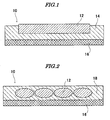


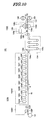
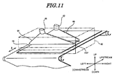


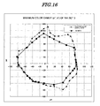
Classifications
-
- B—PERFORMING OPERATIONS; TRANSPORTING
- B41—PRINTING; LINING MACHINES; TYPEWRITERS; STAMPS
- B41M—PRINTING, DUPLICATING, MARKING, OR COPYING PROCESSES; COLOUR PRINTING
- B41M5/00—Duplicating or marking methods; Sheet materials for use therein
- B41M5/0011—Pre-treatment or treatment during printing of the recording material, e.g. heating, irradiating
-
- B—PERFORMING OPERATIONS; TRANSPORTING
- B41—PRINTING; LINING MACHINES; TYPEWRITERS; STAMPS
- B41M—PRINTING, DUPLICATING, MARKING, OR COPYING PROCESSES; COLOUR PRINTING
- B41M2205/00—Printing methods or features related to printing methods; Location or type of the layers
- B41M2205/12—Preparation of material for subsequent imaging, e.g. corona treatment, simultaneous coating, pre-treatments
-
- B—PERFORMING OPERATIONS; TRANSPORTING
- B41—PRINTING; LINING MACHINES; TYPEWRITERS; STAMPS
- B41M—PRINTING, DUPLICATING, MARKING, OR COPYING PROCESSES; COLOUR PRINTING
- B41M7/00—After-treatment of prints, e.g. heating, irradiating, setting of the ink, protection of the printed stock
- B41M7/0081—After-treatment of prints, e.g. heating, irradiating, setting of the ink, protection of the printed stock using electromagnetic radiation or waves, e.g. ultraviolet radiation, electron beams
Definitions
- the present invention relates to an inkjet recording method and, more particularly, to an inkjet recording method employing an undercoat liquid and a colored liquid.
- Inkjet systems in which ink is discharged as droplets from an ink discharge orifice, are employed in many printers for reasons such as small size, low cost, and an ability to form an image without contacting a recording medium.
- a piezo inkjet system in which ink is discharged by utilizing deformation of a piezoelectric element
- a thermal inkjet system in which droplets of ink are discharged by utilizing the phenomenon of boiling of the ink by means of thermal energy, are characterized by their high resolution and high speed printing properties.
- inkjet printers have not been limited only to photographic printing and document printing for home use or office use, and the development of commercial printing equipment and industrial printing equipment employing inkjet printers has been carried out.
- inkjet inks and recording methods intended for use in commercial printing equipment or industrial printing equipment to have (1) wide color reproduction in a formed image, (2) an ability to carry out printing on all types of recording media including nonpermeable recording media such as plastic media, and (3) an ability to carry out high speed printing employing a single pass system.
- Inkjet inks and inkjet recording methods for home use or office use have often been developed for the purpose of printing photographs or documents, and there is the serious problem of their narrow color reproduction as commercial or industrial printed materials.
- 'Fired droplet interference means a phenomenon in which, since liquid droplets fired next to each other coalesce and move, they are displaced from the positions at which they landed, thus causing nonuniformity in line width when drawing fine lines and causing uneven color, etc. when drawing a colored surface.
- JP-A-2000-141616 JP-A denotes a Japanese unexamined patent application publication
- a radiation-curable inkjet ink employing a special pigment such as Pigment Orange or Pigment Green has been disclosed (ref. e.g. JP-PCT-2003-531223 (JP-PCT denotes a published Japanese translation of a PCT application)).
- two reactive liquid inks are used, and they are reacted on a recording medium; for example, there have been disclosed a method in which, after a liquid containing a basic polymer is applied, recording is carried out using an ink containing an anionic dye (ref. e.g. JP-A-63-60783 ), and a method in which, after a liquid composition containing a cationic substance is applied, an ink containing an anionic compound and a colorant is applied (ref. e.g. JP-A-8-174997 ).
- JP-A-63-60783 although problems such as fired droplet interference and spreading can be avoided for a specific substrate, the method is inadequate from the viewpoint of image fixation.
- the method described in JP-A-2003-145745 although spreading is suppressed and image fixation is improved, there is still the problem that images vary between various recording media, and the method is inadequate for solving nonuniformity in line width, color unevenness, etc. due to mixing of droplets.
- the methods described in JP-A-8-174997 and JP-A-2004-42548 are inadequate for solving nonuniformity in line width, color unevenness, etc. due to mixing of droplets.
- the method described in JP-A-2005-96254 still has problems such as nonuniformity in line width and color unevenness due to mixing of droplets.
- the present invention has been accomplished in the light of the above-mentioned circumstances, and it is a particular object of the present invention to provide an inkjet recording method that satisfies at the same time three points, that is, (1) ensuring a color gamut equal to the PANTONE color gamut, (2) having excellent image fixation (rapid drying), and (3) being suitable as a single pass system recording method.
- an inkjet recording method that (1) can ensure a color gamut equal to the PANTONE color gamut, (2) has excellent image fixation (rapid drying), and (3) is suitable as a single pass system recording method.
- the inkjet recording method of the present invention comprises (a) a step of applying an undercoat liquid onto a recording medium, (b) a step of carrying out image formation by discharging a colored liquid onto the undercoat liquid, and (c) a step of curing the colored liquid, the colored liquid being a multiple color ink set comprising a plurality of ink compositions, and the colored liquid comprising an ink composition of at least one color selected from the group consisting of violet, blue, green, orange, and red.
- It preferably comprises a step of semi-curing the undercoat liquid after the step of applying the undercoat liquid and before the step of carrying out image formation, and it more preferably further comprises, after discharging an ink composition of at least one color, a step of semi-curing the ink composition.
- the colored liquid comprises an ink composition of at least one color selected from the group consisting of violet, blue, green, orange, and red, the color reproduction is excellent compared with an inkjet recording method employing a conventional ink composition.
- the present invention is an inkjet recording method in which an undercoat layer is applied onto a recording medium, this is preferably semi-cured, an ink composition that cures upon exposure to actinic radiation is subsequently discharged onto the undercoat liquid, and the discharged ink composition is cured by actinic radiation.
- the colored liquid is a multiple color ink set comprising a plurality of ink compositions (in the present invention, an ink composition is also simply called an ink or an ink liquid).
- an ink composition is also simply called an ink or an ink liquid.
- image formation is carried out by discharging multiple color ink compositions in sequence or at the same time.
- 'semi-curing means curing in part (partially cured; partial curing), and refers to a state in which an undercoat liquid and/or a colored liquid are partially cured but are not completely cured.
- An image in the present invention is optical information including characters, figures, tables, and photographs, and may be any one of black-and-white, monocolor, and full color.
- the undercoat layer after the undercoat layer is applied onto the recording medium and before an ink is applied thereto.
- This can prevent effectively the occurrence of image spreading, nonuniform line width of fine lines in an image, and uneven color of a colored surface. Therefore, in accordance with the inkjet recording method of the present invention, it is possible to form a sharp line with a uniform width, and carry out recording of an inkjet image having high fired droplet density such as reverse characters with good reproduction of a detailed image such as fine lines.
- the inkjet recording method of the present invention is particularly effective when an image is recorded on, for example, a nonpermeable or slowly permeable recording medium having low liquid absorbability as the recording medium.
- the adjacent ink droplets referred to here mean liquid droplets fired from an ink discharge orifice using a single color ink so as to have overlapping parts, or liquid droplets fired from ink discharge orifices using inks with different colors so as to have overlapping parts.
- the adjacent ink droplets may be liquid droplets fired at the same time or may be a preceding liquid droplet and a succeeding liquid droplet, which have a preceding fired droplet and succeeding fired droplet relationship.
- the undercoat liquid has a different composition from that of the ink. It is also preferable that the undercoat liquid is applied to the same region as for an image formed above a recording medium by discharging ink droplets or to a wider region than the image.
- inks of a plurality of colors are used as a multiple color ink set.
- the constitution is preferably such that, after each color ink is discharged, ink droplets thereof are semi-cured.
- droplets of inks of a plurality of colors fired at a recording medium comprise a polymerizing or crosslinking material for forming the image and have a composition different from that of the undercoat liquid, and there are provided a step of applying in advance the undercoat liquid comprising a polymerizing or crosslinking material onto the recording medium in the same region as the image formed from the ink droplets or a wider region than the image, a step of applying actinic radiation or heat to the undercoat liquid applied onto the recording medium, and a step of firing droplets of the inks of a plurality of colors at a side of the recording medium onto which the undercoat liquid has been applied, after the actinic radiation or heat has been applied and semi-curing has been carried out.
- the undercoat liquid is applied in advance as described above and subsequently, at least after all the multiple color ink droplets have been fired, there is provided a step of fixing a recorded image by applying energy.
- Application of energy enables a curing reaction of the contained polymerizing or crosslinking material by polymerization or crosslinking to be promoted, and a stronger image to be formed more efficiently.
- the application of activating energy such as actinic radiation or heat allows the generation of an active species due to decomposition of the polymerization initiator to be promoted, and a curing reaction involving polymerization or crosslinking of a polymerizing or crosslinking material due to the active species is promoted by an increase in the active species or an increase in temperature.
- the application of energy can be carried out suitably by irradiation with actinic radiation or heating.
- actinic radiation the same activating light as that used for image fixation, which will be described later, may be used; examples thereof include ultraviolet rays, visible light, ⁇ rays, ⁇ rays, X rays, and an electron beam, ultraviolet rays and visible light are preferable from the viewpoint of cost and safety, and ultraviolet rays are particularly preferable. Irradiation means will be described later.
- Heating may be carried out using non-contact type heating means, and heating means involving passing through a heating furnace such as an oven, heating means involving overall exposure such as UV light, visible light, IR light, etc. are suitable.
- a heating furnace such as an oven
- heating means involving overall exposure such as UV light, visible light, IR light, etc.
- a light source suitable for light exposure as the heating means a metal halide lamp, a xenon lamp, a tungsten lamp, a carbon arc lamp, a mercury lamp, etc. can be cited.
- the colored liquid is preferably curable by irradiation with actinic radiation.
- energy When energy is applied by irradiation with activating light, although the amount of energy necessary for a curing reaction depends on the type and content of a polymerization initiator, it is generally on the order of at least 100 mJ/cm 2 but no greater than 10,000 mJ/cm 2 (in the present invention, 'at least 100 mJ/cm 2 but no greater than 10,000 mJ/cm 2 ' may be expressed as '100 mJ/cm 2 to 10,000 mJ/cm 2 ' or '100 to 10,000 mJ/cm 2 ', the same applies below). Furthermore, when energy is provided by heating, heating is preferably carried out for 0.1 to 1 sec. under conditions that give a surface temperature of the recording medium in the range of 40°C to 80°C.
- the ink composition forming the colored liquid is constituted such that it becomes a composition forming at least an image.
- the ink composition comprises at least one type of polymerizing or crosslinking material, and further comprises a polymerization initiator, a colorant, and another component.
- the colored liquid is a multiple color ink set comprising a plurality of ink compositions, and comprises an ink composition of at least one color selected from the group consisting of violet, blue, green, orange, and red.
- the colored liquid preferably further comprises ink compositions of each color of cyan, magenta, yellow, black, and white. Using an ink composition of at least one color selected from the group consisting of violet, blue, green, orange, and red as the colored liquid enables an image having excellent color reproduction to be formed.
- the undercoat liquid is preferably constituted so as to have at least a different composition from that of the ink composition.
- the undercoat liquid comprises at least one type of polymerizing or crosslinking material and comprises, as necessary, a polymerization initiator, a colorant, and another component.
- the ink composition comprises a colorant. Furthermore, it is preferable either that the undercoat liquid used in combination with the ink composition does not comprise a colorant or has a colorant content of less than 1 wt %, or that the undercoat liquid comprises as a colorant a white pigment.
- the polymerization initiator is preferably one that initiates a polymerization reaction or a crosslinking reaction by virtue of heat or actinic radiation, and is more preferably one that initiates a polymerization reaction or a crosslinking reaction by virtue of actinic radiation. Due to the ink composition and the undercoat liquid comprising a polymerization initiator, the ink composition and the undercoat liquid applied to the recording medium can preferably be cured by heating or irradiating with actinic radiation.
- the ink composition and the undercoat liquid preferably comprise a radically polymerizable composition.
- the radically polymerizable composition in the present invention means a composition comprising at least one type of radically polymerizable material and at least one type of radical polymerization initiator.
- the radically polymerizable composition enables a curing reaction to be carried out in a short time.
- a polymerization or crosslinking reaction is caused in the polymerizing or crosslinking material by an initiating species such as a radical generated from a polymerization initiator, which will be described later, etc., and a composition containing these has the function of curing.
- an initiating species such as a radical generated from a polymerization initiator, which will be described later, etc.
- a polymerizing or crosslinking material that undergoes a known polymerization or crosslinking reaction such as a radical polymerization reaction or a dimerization reaction may be used.
- a known polymerization or crosslinking reaction such as a radical polymerization reaction or a dimerization reaction
- examples thereof include an addition-polymerizable compound having at least one ethylenically unsaturated double bond, a polymer compound having a maleimide group in a side chain, and a polymer compound having in a side chain a cinnamyl group, a cinnamylidene group, a chalcone group, etc., which have a photodimerizable unsaturated double bond adjacent to an aromatic ring.
- an addition-polymerizable compound having at least one ethylenically unsaturated double bond is preferable, and it is particularly preferably selected from compounds having at least one and more preferably two or more terminal ethylenically unsaturated bonds (monofunctional or polyfunctional compound).
- it may appropriately be selected from those widely known in the industrial field related to the present invention, and examples thereof include those having a chemical form such as a monomer, a prepolymer (i.e. a dimer, a trimer, and an oligomer), a mixture thereof, and a copolymer thereof.
- polymerizing or crosslinking material one type thereof may be used on its own, or two or more types thereof may be used in combination.
- the polymerizing or crosslinking material in the present invention it is particularly preferable to use various types of known radically polymerizable monomers in which a polymerization reaction is caused by an initiating species generated from a radical initiator.
- an ethylenically unsaturated compound is preferable, and examples thereof include a (meth)acrylate, a (meth)acrylamide, an aromatic vinyl compound, a vinyl ether, and a compound having an internal double bond (maleic acid, etc.).
- '(meth)acrylate' means both or either of 'acrylate' and 'methacrylate'
- '(meth)acrylic' means both or either of 'acrylic' and 'methacrylic'.
- monofunctional (meth)acrylates include hexyl (meth)acrylate, 2-ethylhexyl (meth)acrylate, tert -octyl (meth)acrylate, isoamyl (meth)acrylate, decyl (meth)acrylate, isodecyl (meth)acrylate, stearyl (meth)acrylate, isostearyl (meth)acrylate, cyclohexyl (meth)acrylate, 4- n -butylcyclohexyl (meth)acrylate, bornyl (meth)acrylate, isobornyl (meth)acrylate, benzyl (meth)acrylate, 2-ethylhexyldiglycol (meth)acrylate, butoxyethyl (meth)acrylate, 2-chloroethyl (meth)acrylate, 4-bromobutyl (meth)acrylate, cyanoethyl (meth)acryl
- difunctional (meth)acrylates include 1,6-hexanediol di(meth)acrylate, 1,10-decanediol di(meth)acrylate, neopentyl glycol di(meth)acrylate, 2,4-dimethyl-1,5-pentanediol di(meth)acrylate, ethoxylated cyclohexanemethanol di(meth)acrylate, polyethylene glycol di(meth)acrylate, oligoethylene glycol di(meth)acrylate, ethylene glycol di(meth)acrylate, 2-ethyl-2-butylbutanediol di(meth)acrylate, neopentyl glycol hydroxypivalate di(meth)acrylate, EO-modified bisphenol A di(meth)acrylate, bisphenol F polyethoxydi(meth)acrylate, polypropylene glycol di(meth)acrylate, oligopropylene glycol di(
- trifunctional (meth)acrylates include trimethylolpropane tri(meth)acrylate, trimethylolethane tri(meth)acrylate, an alkylene oxide-modified tri(meth)acrylate of trimethylolpropane, pentaerythritol tri(meth)acrylate, dipentaerythritol tri(meth)acrylate, trimethylolpropane tris((meth)acryloyloxypropyl) ether, an isocyanuric acid alkylene oxide-modified tri(meth)acrylate, propionic acid dipentaerythritol tri(meth)acrylate, tris((meth)acryloyloxyethyl) isocyanurate, hydroxypivalaldehyde-modified dimethylolpropane tri(meth)acrylate, sorbitol tri(meth)acrylate, propoxylated trimethylolpropane tri(meth)acrylate, and eth
- tetrafunctional (meth)acrylates include pentaerythritol tetra(meth)acrylate, sorbitol tetra(meth)acrylate, ditrimethylolpropane tetra(meth)acrylate, dipentaerythritol propionate tetra(meth)acrylate, and ethoxylated pentaerythritol tetra(meth)acrylate.
- pentafunctional (meth)acrylates include sorbitol penta(meth)acrylate and dipentaerythritol penta(meth)acrylate.
- hexafunctional (meth)acrylates include dipentaerythritol hexa(meth)acrylate, sorbitol hexa(meth)acrylate, an alkylene oxide-modified hexa(meth)acrylate of phosphazene, and caprolactone-modified dipentaerythritol hexa(meth)acrylate.
- Examples of the (meth)acrylamide include (meth)acrylamide, N -methyl (meth)acrylamide, N -ethyl (meth)acrylamide, N -propyl (meth)acrylamide, N - n -butyl (meth)acrylamide, N - t -butyl (meth)acrylamide, N -butoxymethyl (meth)acrylamide, N- isopropyl (meth)acrylamide, N -methylol (meth)acrylamide, N , N -dimethyl (meth)acrylamide, N , N -diethyl (meth)acrylamide, and (meth)acryloylmorpholine.
- aromatic vinyl compound examples include styrene, methylstyrene, dimethylstyrene, trimethylstyrene, ethylstyrene, isopropylstyrene, chloromethylstyrene, methoxystyrene, acetoxystyrene, chlorostyrene, dichlorostyrene, bromostyrene, methyl vinylbenzoate, 3-methylstyrene, 4-methylstyrene, 3-ethylstyrene, 4-ethylstyrene, 3-propylstyrene, 4-propylstyrene, 3-butylstyrene, 4-butylstyrene, 3-hexylstyrene, 4-hexylstyrene, 3-octylstyrene, 4-octylstyrene, 3-(2-ethylhexyl)styrene,
- vinyl ether examples include, as monofunctional vinyl ethers, methyl vinyl ether, ethyl vinyl ether, propyl vinyl ether, n -butyl vinyl ether, t -butyl vinyl ether, 2-ethylhexyl vinyl ether, n -nonyl vinyl ether, lauryl vinyl ether, cyclohexyl vinyl ether, cyclohexylmethyl vinyl ether, 4-methylcyclohexylmethyl vinyl ether, benzyl vinyl ether, dicyclopentenyl vinyl ether, 2-dicyclopentenoxyethyl vinyl ether, methoxyethyl vinyl ether, ethoxyethyl vinyl ether, butoxyethyl vinyl ether, methoxyethoxyethyl vinyl ether, ethoxyethoxyethyl vinyl ether, methoxy polyethylene glycol vinyl ether, tetrahydrofurfuryl vinyl ether, 2-hydroxyethyl
- polyfunctional vinyl ethers include divinyl ethers such as ethylene glycol divinyl ether, diethylene glycol divinyl ether, polyethylene glycol divinyl ether, propylene glycol divinyl ether, butylene glycol divinyl ether, hexanediol divinyl ether, a bisphenol A alkylene oxide divinyl ether, and a bisphenol F alkylene oxide divinyl ether; and polyfunctional vinyl ethers such as trimethylolethane trivinyl ether, trimethylolpropane trivinyl ether, ditrimethylolpropane tetravinyl ether, glycerol trivinyl ether, pentaerythritol tetravinyl ether, dipentaerythritol pentavinyl ether, dipentaerythritol hexavinyl ether, an ethylene oxide adduct of trimethylolpropane trivin
- vinyl ether compound di- or tri-vinyl ether compounds are preferable from the viewpoint of curability, adhesion to a recording medium, surface hardness of an image formed, etc., and divinyl ether compounds are particularly preferable.
- examples of the radically polymerizable monomer in the present invention include vinyl esters (vinyl acetate, vinyl propionate, vinyl versatate, etc.), allyl esters (allyl acetate, etc.), halogen-containing monomers (vinylidene chloride, vinyl chloride, etc.), vinyl cyanides ((meth)acrylonitrile, etc.), and olefins (ethylene, propylene, etc.).
- (meth)acrylates and (meth)acrylamides are preferable from the viewpoint of curing speed, and tetra- or higher-functional (meth)acrylates are particularly preferable from the viewpoint of curing speed.
- tetra- or higher-functional (meth)acrylates are particularly preferable from the viewpoint of curing speed.
- the mixing ratio (A):(B) of the monofunctional polymerizable compound (A) and the polyfunctional polymerizable compound (B) is preferably 1:1 to 1:4 as a ratio by weight, more preferably 1:1.5 to 1:3, and yet more preferably 1:2 to 1:2.5.
- a cationically polymerizable compound may be used as the polymerizing or crosslinking material.
- a radically polymerizable compound or a cationically polymerizable compound may be used, and the two may be used in combination.
- the cationically polymerizable compound in the present invention is not particularly limited as long as it is a compound that undergoes a cationic polymerization reaction by the application of some type of energy and cures; any type of monomer, oligomer, or polymer may be used and, in particular, various types of known cationically polymerizable monomers, known as cationically photopolymerizable monomers, that undergo a polymerization reaction by an initiating species generated from a cationic polymerization initiator, which will be described later, may be used.
- the cationically polymerizable compound may be a monofunctional compound or a polyfunctional compound.
- an oxetane-ring containing compound and an oxirane ring-containing compound are preferable, and a configuration in which both of an oxetane-ring containing compound and an oxirane ring-containing compound are contained is more preferable.
- the oxirane ring-containing compound (hereinafter, also called an 'oxirane compound' as appropriate) is a compound containing at least one oxirane ring (oxiranyl group, epoxy group) per molecule; it may be appropriately selected from those normally used as epoxy resins, and specific examples thereof include conventionally known aromatic epoxy resins, alicyclic epoxy resins, and aliphatic epoxy resins. It may be any one of a monomer, an oligomer, and a polymer.
- the oxetane-ring containing compound (hereinafter, also called an 'oxetane compound' as appropriate) is a compound containing at least one oxetane ring (oxetanyl group) per molecule.
- Examples of the cationically polymerizable monomer include epoxy compounds, vinyl ether compounds, oxetane compounds described in JP-A-6-9714 , JP-A-2001-31892 , JP-A-2001-40068 , JP-A-2001-55507 , JP-A-2001-310938 , JP-A-2001-310937 , JP-A-2001-220526 , etc.
- Examples of monofunctional epoxy compounds used in the present invention include phenyl glycidyl ether, p - tert -butylphenyl glycidyl ether, butyl glycidyl ether, 2-ethylhexyl glycidyl ether, allyl glycidyl ether, 1,2-butylene oxide, 1,3-butadiene monooxide, 1,2-epoxydodecane, epichlorohydrin, 1,2-epoxydecane, styrene oxide, cyclohexene oxide, 3-methacryloyloxymethylcyclohexene oxide, 3-acryloyloxymethylcyclohexene oxide, and 3-vinylcyclohexene oxide.
- examples of polyfunctional epoxy compounds include bisphenol A diglycidyl ether, bisphenol F diglycidyl ether, bisphenol S diglycidyl ether, brominated bisphenol A diglycidyl ether, brominated bisphenol F diglycidyl ether, brominated bisphenol S diglycidyl ether, epoxy novolac resins, hydrogenated bisphenol A diglycidyl ether, hydrogenated bisphenol F diglycidyl ether, hydrogenated bisphenol S diglycidyl ether, 3,4-epoxycyclohexenylmethyl-3',4'-epoxycyclohexenecarboxylate, 2-(3,4-epoxycyclohexyl)-7,8-epoxy-1,3-dioxaspiro[5.5]undecane, bis(3,4-epoxycyclohexylmethyl) adipate, vinylcyclohexene dioxide, 4-vinylepoxycyclohexane, bis(3,4-e)
- the aromatic epoxides and the alicyclic epoxides are preferable from the viewpoint of excellent curing speed, and the alicyclic epoxides are particularly preferable.
- monofunctional vinyl ethers used in the present invention include methyl vinyl ether, ethyl vinyl ether, propyl vinyl ether, n -butyl vinyl ether, t -butyl vinyl ether, 2-ethylhexyl vinyl ether, n -nonyl vinyl ether, lauryl vinyl ether, cyclohexyl vinyl ether, cyclohexylmethyl vinyl ether, 4-methylcyclohexylmethyl vinyl ether, benzyl vinyl ether, dicyclopentenyl vinyl ether, 2-dicyclopentenoxyethyl vinyl ether, methoxyethyl vinyl ether, ethoxyethyl vinyl ether, butoxyethyl vinyl ether, methoxyethoxyethyl vinyl ether, ethoxyethoxyethyl vinyl ether, methoxypolyethylene glycol vinyl ether, tetrahydrofurfuryl vinyl ether, 2-hydroxyethyl vinyl ether
- polyfunctional vinyl ethers include divinyl ethers such as ethylene glycol divinyl ether, diethylene glycol divinyl ether, polyethylene glycol divinyl ether, propylene glycol divinyl ether, butylene glycol divinyl ether, hexanediol divinyl ether, bisphenol A alkylene oxide divinyl ether, and bisphenol F alkylene oxide divinyl ether; and polyfunctional vinyl ethers such as trimethylolethane trivinyl ether, trimethylolpropane trivinyl ether, ditrimethylolpropane tetravinyl ether, glycerol trivinyl ether, pentaerythritol tetravinyl ether, dipentaerythritol pentavinyl ether, dipentaerythritol hexavinyl ether, an ethylene oxide adduct of trimethylolpropane trivinyl
- the vinyl ether compound the di- or tri-vinyl ether compounds are preferable from the viewpoint of curability, adhesion to a recording medium, surface hardness of the image formed, etc., and the divinyl ether compounds are particularly preferable.
- the oxetane compound in the present invention may be selected freely from known oxetane compounds such as those described in JP-A-2001-220526 , JP-A-2001-310937 , and JP-A-2003-341217 .
- the oxetane compound that can be used in the present invention is preferably a compound having 1 to 4 oxetane rings in its structure. Use of such a compound enables the viscosity of the colored liquid and the undercoat liquid to be maintained in a range that gives ease of handling and enables high adhesion of the colored liquid and/or undercoat liquid to a recording medium after curing to be obtained.
- Examples of monofunctional oxetane compounds used in the present invention include 3-ethyl-3-hydroxymethyloxetane, 3-allyloxymethyl-3-ethyloxetane, (3-ethyl-3-oxetanylmethoxy)methylbenzene, 4-fluoro-[1-(3-ethyl-3-oxetanylmethoxy)methyl]benzene, 4-methoxy-[1-(3-ethyl-3-oxetanylmethoxy)methyl]benzene, [1-(3-ethyl-3-oxetanylmethoxy)ethyl] phenyl ether, isobutoxymethyl (3-ethyl-3-oxetanylmethyl) ether, isobornyloxyethyl (3-ethyl-3-oxetanylmethyl) ether, isobornyl (3-ethyl-3-oxetanylmethyl) ether, 2-ethy
- polyfunctional oxetane compounds include 3,7-bis(3-oxetanyl)-5-oxanonane, 3,3'-(1,3-(2-methylenyl)propanediylbis(oxymethylene))bis-(3-ethyloxetane), 1,4-bis[(3-ethyl-3-oxetanylmethoxy)methyl]benzene, 1,2-bis[(3-ethyl-3-oxetanylmethoxy)methyl]ethane, 1,3-bis[(3-ethyl-3-oxetanylmethoxy)methyl]propane, ethylene glycol bis(3-ethyl-3-oxetanylmethyl) ether, dicyclopentenylbis(3-ethyl-3-oxetanylmethyl) ether, triethylene glycol bis(3-ethyl-3-oxetanylmethyl) ether, tetraethylene glycol bis(3-
- Such oxetane compounds are described in detail in Paragraph Nos. 0021 to 0084 of JP-A-2003-341217 , and compounds described therein can be used suitably in the present invention.
- oxetane compounds used in the present invention from the viewpoint of viscosity and tackiness of the colored liquid and the undercoat liquid, it is preferable to use a compound having 1 to 2 oxetane rings.
- one type may be used on its own, or two or more types may be used in combination.
- the content of the cationically polymerizable compound, relative to the total solids content of the colored liquid and/or undercoat liquid containing the cationically polymerizable compound, is preferably 50 to 95 wt %, more preferably 60 to 92 wt %, and yet more preferably 70 to 90 wt %.
- the content of the polymerizable compound, relative to the total solids content (weight) of each liquid droplet is preferably in the range of 50 to 99.6 wt %, more preferably in the range of 60 to 99.0 wt %, and yet more preferably in the range of 70 to 99.0 wt %.
- the ink and the undercoat liquid may be constituted suitably using at least one type of polymerization initiator, and it is preferable for at least the undercoat liquid to be constituted using a polymerization initiator.
- This polymerization initiator is a compound that generates an initiating species such as a radical by the application of either activating light or heat as energy, or both thereof, initiates and promotes a polymerization or crosslinking reaction of the polymerizing or crosslinking material described above, and cures it.
- a polymerization initiator that causes radical polymerization (radical polymerization initiator)
- a polymerization initiator that causes cationic polymerization (cationic polymerization initiator)
- photopolymerization initiators it is preferable for them to be photopolymerization initiators.
- the photopolymerization initiator is a compound that undergoes chemical change due to the action of light or interaction with an electronically excited state of a sensitizing dye and generates at least one of a radical, an acid, and a base, and it is particularly preferably a photo-radical generator from the viewpoint of polymerization being initiated by the simple means of exposure.
- the cationic polymerization initiator or the radical polymerization initiator in the present invention is a compound that undergoes chemical change due to the action of light or interaction with an electronically excited state of a sensitizing dye and generates a radical, an acid, or a base, and it is particularly preferably the photo-radical generator or a photo-acid generator from the viewpoint of polymerization being initiated by the simple means of exposure.
- a cationic polymerization initiator or a radical polymerization initiator may be used by appropriate selection from polymerization initiators described in detail below while taking into consideration the relationship with a cationically polymerizable compound or radically polymerizable compound that is used in combination.
- the photopolymerization initiator one having sensitivity to actinic radiation applied such as, for example, ultraviolet rays at 400 to 200 nm, far ultraviolet rays, g-line, h-line, i-line, KrF excimer laser light, ArF excimer laser light, an electron beam, X rays, a molecular beam, or an ion beam, may be used by appropriate selection.
- actinic radiation applied such as, for example, ultraviolet rays at 400 to 200 nm, far ultraviolet rays, g-line, h-line, i-line, KrF excimer laser light, ArF excimer laser light, an electron beam, X rays, a molecular beam, or an ion beam.
- a photopolymerization initiator known to a person skilled in the art may be used without limitation, and many specific examples thereof are described in Bruce M. Monroe et al., Chemical Reviews, 93, 435 (1993 ), R. S. Davidson, Journal of Photochemistry and Biology A: Chemistry, 73, 81 (1993 ), J. P. Faussier "Photoinitiated Polymerization-Theory and Applications”: Rapra Review, Vol.9, Report, Rapra Technology (1998 ), and M. Tsunooka et al., Prog. Polym. Sci., 21, 1 (1996 ). Furthermore, many compounds utilized in chemically amplified photoresists and cationic photopolymerization, etc.
- Examples of the preferable photopolymerization initiator include (a) an aromatic ketone, (b) an aromatic onium salt compound, (c) an organic peroxide, (d) a hexaarylbiimidazole compound, (e) a ketoxime ester compound, (f) a borate compound, (g) an azinium compound, (h) a metallocene compound, (i) an active ester compound, and (j) a compound having a carbon-halogen bond.
- Preferred examples of the aromatic ketone (a) include a compound having a benzophenone skeleton (benzophenone compound) or a compound having a thioxanthone skeleton (thioxanthone compound) described in 'RADIATION CURING IN POLYMER SCIENCE AND TECHNOLOGY' J. P. FOUASSIER and J. F. RABEK (1993), pp. 77 to 117 .
- Preferred examples of the aromatic ketone (a), include an ⁇ -thiobenzophenone compound described in JP-B-47-6416 (JP-B denotes a Japanese examined patent application publication), a benzoin ether compound described in JP-B-47-3981 , an ⁇ -substituted benzoin compound described in JP-B-47-22326 , a benzoin derivative described in JP-B-47-23664 , an aroylphosphonic acid ester described in JP-A-57-30704 , a dialkoxybenzophenone described in JP-B-60-26483 , benzoin ethers described in JP-B-60-26403 and JP-A-62-81345 , ⁇ -aminobenzophenones described in JP-B-1-34242 , US Pat.
- JP-B denotes a Japanese examined patent application publication
- JP-B denotes a Japanese examined patent application publication
- aromatic onium salt compound (b) there can be cited aromatic onium salts of elements of Groups 15, 16, and 17 (Groups V B, VI B and VII B) of the periodic table, specifically, N, P, As, Sb, Bi, O, S, Se, Te, and I. Examples thereof include iodonium salts described in EP No. 104143 , US Pat. No. 4837124 , JP-A-2-150848 , and JP-A-2-96514 , diazonium salts (optionally substituted benzenediazoniums, etc.) described in EP Nos. 370693 , 233567 , 297443 , 297442 , 279210 , and 422570 , US Pat. Nos.
- diazonium salt resins diazodiphenylamine formaldehyde resins, etc.
- N-alkoxypyridinium salts etc.
- JP-A-63-138345 JP-A-63-142345 , JP-A-63-142346 , and JP-B-46-42363 ; specific examples thereof include 1-methoxy-4-phenylpyridinium tetrafluoroborate); furthermore, compounds described in JP-B-52-147277 , 52-14278 , and 52-14279 may suitably be used.
- a radical or an acid is formed as an active species.
- organic peroxide (c) almost all organic compounds having at least one oxygen-oxygen bond per molecule can be cited, and preferred examples thereof include peroxide ester compounds such as 3,3',4,4'-tetra(t-butylperoxycarbonyl)benzophenone, 3,3',4,4'-tetra(t-amylperoxycarbonyl)benzophenone, 3,3',4,4'-tetra(t-hexylperoxycarbonyl)benzophenone, 3,3',4,4'-tetra(t-octylperoxycarbonyl)benzophenone, 3,3',4,4'-tetra(cumylperoxycarbonyl)benzophenone, 3,3',4,4'-tetra(p-isopropylcumylperoxycarbonyl)benzophenone, and di-t-butyldiperoxyisophthalate.
- peroxide ester compounds such as 3,3',4,4'-tetra(t
- lophine dimers described in JP-B-45-37377 and JP-B-44-86516 there can be cited lophine dimers described in JP-B-45-37377 and JP-B-44-86516 , and examples thereof include 2,2'-bis(o-chlorophenyl)-4,4',5,5'-tetraphenylbiimidazole, 2,2'-bis(o-bromophenyl)-4,4',5,5'-tetraphenylbiimidazole, 2,2'-bis(o,p-dichlorophenyl)-4,4',5,5'-tetraphenylbiimidazole, 2,2'-bis(o-chlorophenyl)-4,4',5,5'-tetra(m-methoxyphenyl)biimidazole, 2,2'-bis(o,o'-dichlorophenyl)-4,4',5,5'-tetrapheny
- ketoxime ester compound (e) there can be cited 3-benzoyloxyiminobutan-2-one, 3-acetoxyiminobutan-2-one, 3-propionyloxyiminobutan-2-one, 2-acetoxyiminopentan-3-one, 2-acetoxyimino-1-phenylpropan-1-one, 2-benzoyloxyimino-1-phenylpropan-1-one, 3-p-toluenesulfonyloxyiminobutan-2-one, and 2-ethoxycarbonyloxyimino-1-phenylpropan-1-one.
- borate compound (f) examples include compounds described in US Pat. Nos. 3,567,453 and 4,343,891 , and EP Nos. 109,772 and 109,773 .
- Examples of the azinium salt compound (g) include N-O bond-containing compounds described in JP-A-63-138345 , JP-A-63-142345 , JP-A-63-142346 , JP-A-63-143537 , and JP-B-46-42363 .
- metallocene compound (h) examples include titanocene compounds described in JP-A-59-152396 , JP-A-61-151197 , JP-A-63-41484 , JP-A-2-249 , and JP-A-2-4705 , and iron-arene complexes described in JP-A-1-304453 and JP-A-1-152109 .
- titanocene compound examples include dichlorobis(cyclopentadienyl)titanium, bis(cyclopentadienyl)bis(phenyl)titanium, bis(cyclopentadienyl)bis(2,3,4,5,6-pentafluorophen-1-yl)titanium, bis(cyclopentadienyl)bis(2,3,5,6-tetrafluorophen-1-yl)titanium, bis(cyclopentadienyl)bis(2,4,6-trifluorophen-1-yl)titanium, bis(cyclopentadienyl)bis(2,6-difluorophen-1-yl)titanium, bis(cyclopentadienyl)bis(2,4-difluorophen-1-yl)titanium, bis(methylcyclopentadienyl)bis(2,3,4,5,6-pentafluorophen-1-yl)titanium
- Examples of the active ester compound (i) include nitrobenzyl ester compounds described in EP Nos. 0290750 , 046083 , 156153 , 271851 , and 0388343 , US Pat. Nos. 3901710 and 4181531 , JP-A-60-198538 , and JP-A-53-133022 , iminosulfonate compounds described in EP Nos. 0199672 , 84515 , 199672 , 044115 , and 0101122 , US Pat. Nos.
- Preferred examples of the compound (j) having a carbon-halogen bond include a compound described in Wakabayashi et. al, Bull. Chem. Soc. Japan, 42, 2924 (1969 ), a compound described in British Patent No. 1388492 , a compound described in JP-A-53-133428 , and a compound described in German Patent No. 3337024 .
- Examples further include a compound described in F. C. Schaefer et al., J. Org. Chem., 29, 1527 (1964 ), a compound described in JP-A-62-58241 , a compound described in JP-A-5-281728 , a compound described in German Pat. No. 2641100 , a compound described in German Pat. No. 3333450 , compounds described in German Pat. No. 3021590 , and compounds described in German Pat. No. 3021599 .
- an aromatic ketone is preferable among those described above, a compound having a benzophenone skeleton or a thioxanthone skeleton is more preferable, and an ⁇ -aminobenzophenone compound and an acylphosphine sulfide compound are particularly preferable.
- an aromatic onium salt is preferable among those described above, an iodonium salt and a sulfonium salt are more preferable, and an iodonium PF 6 salt and a sulfonium PF 6 salt are particularly preferable.
- cationic polymerization initiator and the radical polymerization initiator one type thereof may be used on its own or two or more types may be used in combination. They may be used in a combination with a known sensitizer for the purpose of improving sensitivity as long as the effects of the present invention are not impaired.
- the content of the cationic polymerization initiator and the radical polymerization initiator, relative to the total solids content of the colored liquid and/or undercoat liquid containing the polymerization initiator, is preferably 0.1 to 20 wt %, more preferably 0.5 to 10 wt %, and yet more preferably 1 to 7 wt %.
- cationic polymerization initiator:cationically polymerizable compound or radical polymerization initiator:radically polymerizable compound 0.5:100 to 30:100, more preferably 1:100 to 15:100, and yet more preferably 2:100 to 10:100.
- the polymerization initiator may be contained in the undercoat liquid as well as in the ink, and in this case it is preferable that the polymerization initiator is appropriately selected to be in a range that enables ink storage stability to be maintained at a desired level.
- the colored liquid is a multiple color ink set comprising a plurality of ink compositions
- the colored liquid comprises an ink composition of at least one color selected from the group consisting of violet, blue, green, orange, and red.
- the colored liquid preferably comprises an ink composition of at least one color selected from the group consisting of violet, blue, green, orange, and red and at least one ink composition selected from the group consisting of a cyan color ink composition (cyan ink composition), a magenta color ink composition (magenta ink composition), a yellow color ink composition (yellow ink composition), a black color ink composition (black ink composition), and a white color ink composition (white ink composition).
- the colorant preferably comprises at least one ink composition selected from the group consisting of violet, green, and orange, and preferably comprises violet, green, and orange ink compositions (violet ink composition, green ink composition, and orange ink composition respectively).
- the colored liquid preferably comprises a cyan ink composition, a magenta ink composition, a yellow ink composition, a black ink composition, and a white ink composition, and is particularly preferably a multiple color ink set comprising ink compositions of eight colors, that is, a violet ink composition, a green ink composition, an orange ink composition, a cyan ink composition, a magenta ink composition, a yellow ink composition, a black ink composition, and a white ink composition.
- the ink composition preferably comprises at least one type of colorant.
- Each color ink composition comprises at least one type of colorant exhibiting the corresponding color.
- the undercoat liquid may comprise a colorant.
- a white colorant may suitably be used.
- the colorant that can be used in the present invention is not particularly limited, and it may be appropriately selected from known water-soluble dyes, oil-soluble dyes, and pigments, and used.
- the ink composition and the undercoat liquid used in the present invention are preferably water-insoluble organic solvent-based, and an oil-soluble dye and a pigment, which are easily dispersed and dissolved uniformly in a water-insoluble medium, are preferable.
- the content of the colorant in the ink composition used in the present invention is preferably 1 to 30 wt % of the ink composition, more preferably 1.5 to 25 wt %, and particularly preferably 2 to 15 wt %.
- the undercoat liquid used in the present invention contains a colorant such as a white pigment
- the content thereof in the undercoat liquid is 2 to 45 wt %, and preferably 4 to 35 wt %.
- Pigments suitable for the ink composition and the undercoat liquid used in the present invention are explained in detail below.
- a mode in which a pigment is used as a colorant is preferable.
- the pigment either an organic pigment or an inorganic pigment may be used, and as a black pigment a carbon black pigment, etc. is preferable.
- pigments with a black color and three primary colors, that is, cyan, magenta, and yellow, are used, but in the present invention it is preferable for a pigment of at least one color selected from the group consisting of violet, blue, green, orange, and red to be contained.
- an ink composition comprising a pigment selected from the group consisting of violet, green, and orange
- an ink composition comprising a violet pigment, an ink composition comprising a green pigment, and an ink composition comprising an orange pigment.
- a pigment with another color hue such as a metallic luster pigment such as gold or silver, or a colorless or light-colored extender pigment, etc. may be used according to an intended application.
- a colorant contained in the ink composition at least a colorant exhibiting any color selected from the group consisting of violet, blue, green, orange, and red is used.
- the colorant is preferably an organic pigment.
- a colorant exhibiting a violet color is defined as a colorant for which the hue (a * , b * ) of a film obtained by coating a dispersion of the colorant is in the range 'b * > - 2a * -20 and b * ⁇ 0.5a * +10 (a * > 0, b * ⁇ 0)'.
- a colorant exhibiting a blue color is defined as a colorant for which the hue (a * , b * ) of a film obtained by coating a dispersion of the colorant is in the range 'b * > -a * -20 and b * ⁇ 30a * -30 (a* > 0, b * ⁇ 0)'
- a colorant exhibiting a green color is defined as a colorant for which the hue (a * , b * ) of a film obtained by coating a dispersion of the colorant is in the range 'b * ⁇ -a * +20 and b * > -0.25a * (a * ⁇ 0)'
- a colorant exhibiting an orange color is defined as a colorant for which the hue (a * , b * ) of a film obtained by coating a dispersion of the colorant is in the range 'b * ⁇ 2a * +20 and b * > a * -20 (a * > 0, b * >
- Measurement of hue (a * , b * ) may be carried out using an SPM100-II manufactured by Gretag.
- the concentration of a pigment in a dispersion used here for evaluation of the hue is preferably at least 1 wt % but no greater than 30 wt %.
- the particle size (volume-average particle size) of the pigment in the dispersion is not particularly limited, but from the viewpoint of suppressing the influence of optical scattering it is preferably no greater than 1 ⁇ m, more preferably no greater than 500 nm, and particularly preferably no greater than 200 nm.
- a dispersion medium is not particularly limited as long as there is little coloration or no coloration, and water, a general-purpose solvent, a commercial monomer, etc. are preferable.
- a step of preparing a dispersion is not particularly limited, and a known technique may be used. Since it is relatively simple, ball mill dispersion, bead mill dispersion, ultrasonic dispersion, etc. are preferable. Furthermore, it is preferable to use as appropriate a commercial surfactant or a pigment-dispersing agent during dispersion.
- a white substrate is preferable. It is not particularly limited as long as it is a white substrate and, for example, a commercial white coated paper, a white synthetic paper, etc. are preferable.
- Means for applying a dispersion is not particularly limited and, for example, a bar coater is simple and may preferably be used.
- the hue of a colorant may be measured as follows. 10 parts by weight of colorant (preferably an organic pigment) is dispersed in 100 parts by weight of MEK (methyl ethyl ketone) using a DYNO-MILL (Shinmaru Enterprises Corp.) for 120 minutes. A colorant dispersion thus obtained is applied onto white Yupo 80 paper (Lintec Corp.) at 6 mL/m 2 using a K4 bar.
- colorant preferably an organic pigment
- MEK methyl ethyl ketone
- a pigment exhibiting a violet color, a pigment exhibiting a green color, and a pigment exhibiting an orange color are preferably used.
- the hue (a * , b * ) of a film obtained by applying a dispersion of a pigment exhibiting an orange color is in the range of 'b * ⁇ 2a * and b * > a * (a * > 0, b * > 0)'.
- the hue (a * , b * ) of a film obtained by applying a dispersion of a pigment exhibiting a violet color is in the range of 'b * > -2a * and b * ⁇ 0.5a * (a * > 0, b * ⁇ 0)'
- the hue (a * , b * ) of a film obtained by applying a dispersion of a pigment exhibiting a green color is in the range of 'b * ⁇ -a * (a * ⁇ 0, b * > 0)'.
- Organic pigments exhibiting any of the colors of violet, blue, green, orange, and red are not particularly limited as long as the above-mentioned hue is satisfied, and they may be selected appropriately from commercial products.
- C.I. Pigment Violet 1 (Rhodamine B), C.I. Pigment Violet 2 (Rhodamine 3B), C.I. Pigment Violet 3 (Methyl Violet Lake), C.I. Pigment Violet 3:1 (Methyl Violet Lake), C.I. Pigment Violet 3:3 (Methyl Violet Lake), C.I. Pigment Violet 5:1 (Alizarin Maroon), C.I. Pigment Violet 13 (Ultramarine Pink), C.I. Pigment Violet 17 (Naphthol AS), C.I. Pigment Violet 23 (Dioxazine Violet), C.I. Pigment Violet 25 (Naphthol AS), C.I.
- Pigment Violet 29 (Perylene Violet), C.I. Pigment Violet 31 (Violanthrone Violet), C.I. Pigment Violet 32 (Benzimidazolone Bordeaux HF3R), C.I. Pigment Violet 36 (Thioindigo), C.I. Pigment Violet 37 (Dioxazine Violet), C.I. Pigment Violet 42 (Quinacridone Maroon B), C.I. Pigment Violet 50 (Naphthol AS), etc. are commercially available products.
- C.I. Pigment Blue 1 As pigments exhibiting a blue color, C.I. Pigment Blue 1, C.I. Pigment Blue 2, C.I. Pigment Blue 16, C.I. Pigment Blue 22, C.I. Pigment Blue 60, C.I. Pigment Blue 66, etc. are commercially available products.
- C.I. Pigment Green 1 (Brilliant Green Lake), C.I. Pigment Green 4 (Malachite Green Lake), C.I. Pigment Green 7 (Phthalocyanine Green), C.I. Pigment Green 8 (Pigment Green B), C.I. Pigment Green 10 (Nickel Azo Yellow), C.I. Pigment Green 36 (Brominated Phthalocyanine Green), etc. are commercially available products.
- C.I. Pigment Orange 1 As pigments exhibiting an orange color, C.I. Pigment Orange 1 (Hanza Yellow 3R), C.I. Pigment Orange 2 (Orthonitro Orange), C.I. Pigment Orange 3 ( ⁇ -Naphthol), C.I. Pigment Orange 4 (Naphthol AS), C.I. Pigment Orange 5 ( ⁇ -Naphthol), C.I. Pigment Orange 13 (Pyrazolone Orange G), C.I. Pigment Orange 15 (Dis-Azo Orange), C.I. Pigment Orange 16 (Anisidine Orange), C.I. Pigment Orange 17 (Persian Orange Lake), C.I. Pigment Orange 19 (Naphthalene Yellow Lake), C.I.
- Pigment Orange 24 (Naphthol Orange Y), C.I. Pigment Orange 31 (Condensed Azo Orange), C.I. Pigment Orange 34 (Pyrazolone Orange), C.I. Pigment Orange 36 (Benzimidazolone Orange HL), C.I. Pigment Orange 38 (Naphthol Orange), C.I. Pigment Orange 40 (Pyranthrone Orange), C.I. Pigment Orange 43 (Perinone Orange), C.I. Pigment Orange 46 (Ethyl Red Lake C), C.I. Pigment Orange 48 (Quinacridone Gold), C.I. Pigment Orange 49 (Quinacridone Gold), C.I. Pigment Orange 51 (Pyranthrone Orange), C.I.
- Pigment Orange 60 (Imidazolone Orange HGL), C.I. Pigment Orange 61 (Isoindolinone Orange), C.I. Pigment Orange 62 (Benzimidazolone Orange H5G), C.I. Pigment Orange 64 (Benzimidazolone), C.I. Pigment Orange 65 (Azomethine Orange), C.I. Pigment Orange 66 (Isoindolinone Orange), C.I. Pigment Orange 67 (Pyrazoloquinazolone Orange), C.I. Pigment Orange 68 (Azomethine Orange), C.I. Pigment Orange 69 (Isoindolinone Orange), C.I. Pigment Orange 71 (Diketopyrrolopyrrole Orange), C.I.
- Pigment Orange 72 (Imidazolone Orange H4GL), C.I. Pigment Orange 73 (Diketopyrrolopyrrole Orange), C.I. Pigment Orange 74 (Naphthol Orange 2RLD), C.I. Pigment Orange 81 (Diketopyrrolopyrrole Orange), etc. are commercially available products.
- C.I. Pigment Red 171, C.I. Pigment Red 175, C.I. Pigment Red 176, C.I. Pigment Red 177, C.I. Pigment Red 209, C.I. Pigment Red 220, C.I. Pigment Red 224, C.I. Pigment Red 242, C.I. Pigment Red 254, C.I. Pigment Red 255, C.I. Pigment Red 264, C.I. Pigment Red 270, etc. are commercially available products.
- C.I. Pigment Violet 23 is preferable as the pigment exhibiting a violet color
- C.I. Pigment Orange 36 is preferable as the pigment exhibiting an orange color
- C.I. Pigment Green 7 is preferable as the pigment exhibiting a green color.
- ink compositions comprising the above-mentioned pigments and color ink compositions comprising cyan, magenta, yellow, black, or white pigments and/or dyes.
- pigments exhibiting a magenta color include monoazo pigments such as C.I. Pigment Red 3 (Toluidine Red, etc.), disazo pigments such as CI Pigment Red 38 (Pyrazolone Red B, etc.), azo lake pigments such as C.I. Pigment Red 53:1 (Lake Red C, etc.) and C.I. Pigment Red 57:1 (Brilliant Carmine 6B), condensed azo pigments such as C.I. Pigment Red 144 (Azo Condensation Red BR, etc.), perinone pigments such as C.I. Pigment Red 194 (Perinone Red, etc.), perylene pigments such as C.I.
- monoazo pigments such as C.I. Pigment Red 3 (Toluidine Red, etc.)
- disazo pigments such as CI Pigment Red 38 (Pyrazolone Red B, etc.
- azo lake pigments such as C.I. Pigment Red 53:1 (Lake Red C,
- Pigment Red 149 Perylene Scarlet, etc.
- quinacridone pigments such as C.I. Pigment violet 19 (unsubstituted quinacridone, CINQUASIA Magenta RT-355T; manufactured by Ciba Specialty Chemicals) and C.I. Pigment Red 122 (Quinacridone Magenta, etc.)
- isoindolinone pigments such as C.I. Pigment Red 180 (Isoindolinone Red 2BLT, etc.)
- alizarin lake pigments such as C.I. Pigment Red 83 (Madder Lake, etc.).
- pigments exhibiting a cyan color examples include disazo pigments such as C.I. Pigment Blue 25 (Dianisidine Blue, etc.), phthalocyanine pigments such as C.I. Pigment Blue 15 and C.I. Pigment Blue 15:3 (IRGALITE BLUE GLO; manufactured by Ciba Specialty Chemicals) (Phthalocyanine Blue, etc.), acidic dye lake pigments such as C.I. Pigment Blue 24 (Peacock Blue Lake, etc.), and alkali blue pigments such as C.I. Pigment Blue 18 (Alkali Blue V-5:1).
- disazo pigments such as C.I. Pigment Blue 25 (Dianisidine Blue, etc.)
- phthalocyanine pigments such as C.I. Pigment Blue 15 and C.I. Pigment Blue 15:3 (IRGALITE BLUE GLO; manufactured by Ciba Specialty Chemicals) (Phthalocyanine Blue, etc.)
- acidic dye lake pigments such as C.I
- pigments exhibiting a yellow color examples include monoazo pigments such as C.I. Pigment Yellow 1 (Fast Yellow G, etc.) and C.I. Pigment Yellow 74, disazo pigments such as CI Pigment Yellow 12 (Disazo Yellow AAA, etc.) and C.I. Pigment Yellow 17, benzidine-free azo pigments such as C.I. Pigment Yellow 180 and C.I. Pigment Yellow 200 (Novoperm Yellow 2HG), azo lake pigments such as CI Pigment Yellow 100 (Tartrazine Yellow Lake, etc.), condensed azo pigments such as C.I. Pigment Yellow 95 (Azo Condensation Yellow GR, etc.), acidic dye lake pigments such as C.I.
- Pigment Yellow 115 Quinoline Yellow Lake, etc.
- basic dye lake pigments such as C.I. Pigment Yellow 18 (Thioflavine Lake, etc.)
- anthraquinone pigments such as Flavanthrone Yellow (Y-24)
- isoindolinone pigments such as Isoindolinone Yellow 3RLT (Y-110)
- quinophthalone pigments such as Quinophthalone Yellow (Y-138)
- isoindoline pigments such as Isoindoline Yellow (Y-139)
- nitroso pigments such as C.I. Pigment Yellow 153 (Nickel Nitroso Yellow, etc.
- metal complex azomethine pigments such as C.I. Pigment Yellow 117 (Copper Azomethine Yellow, etc.).
- pigments exhibiting a black color include carbon black, titanium black, and aniline black.
- carbon black examples include SPECIAL BLACK 250 (manufactured by Degussa).
- pigments exhibiting a white color include PigmentWhite 6, 18, 21.
- white pigments that can be used include basic lead carbonate (2PbCO 3 Pb(OH) 2 , also known as silver white), zinc oxide (ZnO, also known as zinc white), titanium oxide (TiO 2 , also known as titanium white), and strontium titanate (SrTiO 3 , also known as titan strontium white).
- Titanium oxide has, compared with other white pigments, a low specific gravity, a high refractive index, and is chemically and physically stable, and therefore has high hiding power and coloring power as a pigment and, furthermore, has excellent durability toward acids, alkalis, and other environments. It is therefore preferable to use titanium oxide as the white pigment. It is of course possible to use another white pigment (which can be any white pigment, in addition to the white pigments cited above) as necessary.
- the pigment exhibiting a cyan color is Pigment Blue 15:3 or Pigment Blue 15:4, the pigment exhibiting a magenta color is Pigment Red 122 or Pigment Violet 19, and the pigment exhibiting a yellow color is Pigment Yellow 180 or Pigment Yellow 155. Furthermore, it is preferable that the pigment exhibiting a white color is titanium oxide.
- a pigment particles formed by adhering a dye or a pigment to the surface of particles of silica, alumina, resin, etc.
- a resin-covered pigment This is called a microcapsule pigment, and commercial products thereof are available from Dainippon Ink and Chemicals, Incorporated, Toyo Ink Mfg. Co., Ltd., etc.
- a dispersing machine such as a bead mill, a ball mill, a sand mill, an attritor, a roll mill, a jet mill, a homogenizer, a paint shaker, a kneader, an agitator, a Henschel mixer, a colloidal mill, an ultrasonic homogenizer, a pearl mill, or a wet type jet mill may be used.
- a dispersant such as a surfactant may be added.
- the colorant when added, as a dispersion adjuvant, it is also possible to use a synergist as necessary according to the various types of colorant.
- the dispersion adjuvant are preferably used at at least 1 part by weight but no greater than 50 parts by weight relative to 100 parts by weight of the colorant.
- a solvent may be added as a dispersion medium for various components such as the colorant, or the polymerizing or crosslinking material, which is a low molecular weight component, may be used as a dispersion medium without using a solvent, and since the colored liquid and the undercoat liquid are preferably an actinic radiation curing type liquid and are cured after being applied on top of a recording medium, it is preferable for it to be solvent-free. This is because, if solvent remains in the image formed from the cured colored liquid and the cured undercoat liquid, the solvent resistance is degraded and the VOC (Volatile Organic Compound) problem of residual solvent occurs.
- VOC Volatile Organic Compound
- the polymerizable compound as a dispersion medium and it is particularly preferable to select a polymerizable compound having the lowest viscosity in terms of improvement of dispersion suitability and handling properties of an ink composition.
- the average particle size of the colorant used here is at least 0.01 ⁇ m but no greater than 0.4 ⁇ m, and more preferably at least 0.02 ⁇ m but no greater than 0.2 ⁇ m.
- the maximum particle size be no greater than 3 ⁇ m, and preferably no greater than 1 ⁇ m, it is preferable for the colorant, the dispersant, and the dispersion medium to be selected, and dispersion conditions and filtration conditions to be set.
- the particle size of the colorant in the colored liquid and the undercoat liquid may be measured by a known measurement method. Specifically, it may be measured by a centrifugal sedimentation light transmission method, an X-ray transmission method, a laser diffraction/scattering method, or a dynamic light scattering method. In the present invention, a value obtained by measurement using the laser diffraction/scattering method is employed.
- the content of the colorant in the colored liquid is appropriately selected according to color and intended application, and from the viewpoint of image density and storage stability it is preferably, relative to the weight of the total ink composition, 0.5 to 30 wt %, more preferably 1.0 to 20 wt %, and particularly preferably 2.0 to 10 wt %.
- one type thereof may be used on its own or two or more types thereof may be used in combination.
- two or more types of organic pigments, or a solid solution of organic pigments may be used in combination.
- Different colorants may be used for each of fired liquid droplets or liquids, or the same colorant may be used.
- a dispersant when dispersing the colorant.
- the type of dispersant is not particularly limited, but it is preferable to use a polymeric dispersant.
- the polymeric dispersant include polymeric dispersants such as DisperBYK-101, DisperBYK-102, DisperBYK-103, DisperBYK-106, DisperBYK-111, DisperBYK-161, DisperBYK-162, DisperBYK-163, DisperBYK-164, DisperBYK-166, DisperBYK-167, DisperBYK-168, DisperBYK-170, DisperBYK-171, DisperBYK-174, and DisperBYK-182 (all manufactured by BYK Chemie), EFKA4010, EFKA4046, EFKA4080, EFKA5010, EFKA5207, EFKA5244, EFKA6745, EFKA6750, EFKA7414, EFKA7462,
- a pigment derivative such as a phthalocyanine derivative (product name: EFKA-745 (manufactured by EFKA)), or Solsperse 5000, 12000, or 22000 (manufactured by Avecia).
- the content of the dispersant in the ink composition is appropriately selected according to an intended application, and it is preferably 0.01 to 5 wt % relative to the weight of the total ink composition.
- the undercoat liquid comprises a white pigment, etc.
- the undercoat liquid it is preferable for the undercoat liquid to also contain a dispersant, the content of the dispersant is appropriately selected according to intended application, and relative to the weight of the total undercoat liquid, it is preferably 0.01 to 5 wt %.
- a surfactant to the ink composition for the purpose of giving discharge properties that are stable for a long period of time. Furthermore, it is preferable to add a surfactant to the undercoat liquid for the purpose of improving wettability toward a recording medium and preventing repellence.
- the surfactant in the present invention is a material that exhibits strong surface activity toward at least one type of solvent from among hexane, cyclohexane, p -xylene, toluene, ethyl acetate, methyl ethyl ketone, butyl carbitol, cyclohexanone, triethylene glycol monobutyl ether, 1,2-hexanediol, propylene glycol monomethyl ether, isopropanol, methanol, water, isobornyl acrylate, 1,6-hexanediacrylate, and polyethylene glycol diacrylate, is preferably a material that exhibits strong surface activity toward at least one type of solvent from among hexane, toluene, propylene glycol monomethyl ether, isobornyl acrylate, 1,6-hexanediol diacrylate, and polyethylene glycol diacrylate, is more preferably a material that exhibits strong surface
- Whether or not a certain compound is a material that exhibits strong surface activity toward a given solvent can be evaluated by the following procedure.
- a solvent is selected, and the surface tension ( ⁇ solvent (0)) of said solvent is measured.
- a compound in question is added to the same solvent as that for which the ⁇ solvent (0) has been determined, the concentration of said compound is increased by 0.01 wt % at a time, and when the change in surface tension for the change in concentration of said compound becomes 0.01 mN/m or below, the surface tension of the solution ( ⁇ solvent (saturated)) is measured. If the relationship between ⁇ solvent (0) and ⁇ solvent (saturated) satisfies ⁇ solvent 0 - ⁇ solvent saturated > 1 mN / m , it can be determined that said compound is a material that exhibits strong surface activity toward said solvent.
- the surfactant used in the ink composition and the undercoat liquid include anionic surfactants such as a dialkylsulfosuccinate, an alkylnaphthalenesulfonate, and a fatty acid salt, nonionic surfactants such as a polyoxyethylene alkyl ether, a polyoxyethylene alkyl allyl ether, acetylene glycol, or a polyoxyethylene/polyoxypropylene block copolymer, cationic surfactants such as an alkylamine salt or a quaternary ammonium salt, and fluorine-based surfactants.
- examples of the surfactant include those described in JP-A-62-173463 and JP-A-62-183457 .
- organofluoro compound may be used as the surfactant.
- the organofluoro compound is preferably hydrophobic.
- examples of the organofluoro compound include fluorine-based surfactants, oil-like fluorine-based compounds (e.g. fluorine oil), solid fluorine compound resins (e.g. tetrafluoroethylene resin), and those described in JP-B-57-9053 (paragraphs 8 to 17) and JP-A-62-135826 .
- fluorine-based additive surfactant/surface modifying agent
- a silicon-based surfactant such as polyether-modified polydimethylsiloxane or a polyether-modified hydroxy group-containing polydimethylsiloxane may be used.
- examples thereof include BYK-306, BYK-307, BYK-308, BYK-310, BYK-330, BYK-333, BYK-341, and BYK-344 (manufactured by BYK-Chemie).
- These surfactants have a high ability to lower surface tension, can improve wettability toward a recording medium, and can prevent repellence.
- the content of the surfactant in the ink composition and the undercoat liquid is appropriately selected according to an intended application, in general it is preferably 0.0001 to 1 wt % relative to the weight of the total ink composition or undercoat liquid. It is preferable that the surface tension of the undercoat liquid is lower than the surface tension of at least one ink composition, and the amount of surfactant added can be adjusted within the above-mentioned range as necessary.
- sensitizing dye As a sensitizer in the ink composition of the present invention, it is preferable to use a sensitizing dye.
- Preferred examples of the sensitizing dye include those that belong to compounds below and have an adsorption wavelength in the region of 350 nm to 450 nm.
- Polynuclear aromatic compounds e.g. pyrene, perylene, triphenylene
- xanthenes e.g. fluorescein, eosin, erythrosine, rhodamine B, rose bengal
- cyanines e.g. thiacarbocyanine, oxacarbocyanine
- merocyanines e.g. merocyanine, carbomerocyanine
- thiazines e.g. thionine, methylene blue, toluidine blue
- acridines e.g. acridine orange, chloroflavin, acriflavine
- anthraquinones e.g. anthraquinone
- squaryliums e.g. squarylium
- coumarins e.g. 7-diethylamino-4-methylcoumarin
- Preferred examples of the sensitizing dye include compounds represented by Formulae (IX) to (XIII) below.
- a 1 denotes a sulfur atom or NR 50
- R 50 denotes an alkyl group or an aryl group
- L 2 denotes a non-metallic atomic group forming a basic nucleus of a dye in cooperation with a neighboring A 1 and the neighboring carbon atom
- R 51 and R 52 independently denote a hydrogen atom or a monovalent non-metallic atomic group
- R 51 and R 52 may be bonded together to form an acidic nucleus of a dye.
- W denotes an oxygen atom or a sulfur atom.
- Ar 1 and Ar 2 independently denote an aryl group and are connected to each other via a bond of -L 3 -.
- L 3 denotes -O- or -S-.
- W has the same meaning as that shown in Formula (IX).
- a 2 denotes a sulfur atom or NR 59
- L 4 denotes a non-metallic atomic group forming a basic nucleus of a dye in cooperation with the neighboring A 2 and carbon atom
- R 53 , R 54 , R 55 , R 56 , R 57 , and R 58 independently denote a monovalent non-metallic atomic group
- R 59 denotes an alkyl group or an aryl group.
- a 3 and A 4 independently denote -S-, -NR 62 -, or -NR 63 -, R 62 and R 63 independently denote a substituted or unsubstituted alkyl group, or a substituted or unsubstituted aryl group, L 5 and L 6 independently denote a non-metallic atomic group forming a basic nucleus of a dye in cooperation with the neighboring A 3 and A 4 and neighboring carbon atom, and R 60 and R 61 independently denote a hydrogen atom or a monovalent non-metallic atomic group, or are bonded to each other to form an aliphatic or aromatic ring.
- R 66 denotes an aromatic ring or a hetero ring, which may have a substituent
- a 5 denotes an oxygen atom, a sulfur atom, or -NR 67 -.
- R 64 , R 65 , and R 67 independently denote a hydrogen atom or a monovalent non-metallic atomic group, and R 67 and R 64 , and R 65 and R 67 may be bonded to each other to form an aliphatic or aromatic ring.
- the ink composition and the undercoat liquid used in the present invention may comprise, in addition to the above-mentioned components, a co-sensitizer, a storage stabilizer, a conductive salt, a solvent, a polymerization inhibitor, and other additives according to an intended application.
- a known compound having a function of further improving sensitivity, suppressing inhibition of polymerization by oxygen, etc. may be added as a co-sensitizer.
- the co-sensitizer include amines such as compounds described in M. R. Sander et al., 'Journal of Polymer Society' Vol. 10, p.
- JP-B-44-20189 JP-A-51-82102 , JP-A-52-134692 , JP-A-59-138205 , JP-A-60-84305 , JP-A-62-18537 , JP-A-64-33104 , and Research Disclosure 33825, and specific examples thereof include triethanolamine, ethyl p -dimethylaminobenzoate, p-formyldimethylaniline, and p -methylthiodimethylaniline.
- cosensitizer examples include thiols and sulfides such as thiol compounds described in JP-A-53-702 , JP-B-55-500806 , and JP-A-5-142772 , and disulfide compounds of JP-A-56-75643 , and specific examples thereof include 2-mercaptobenzothiazole, 2-mercaptobenzoxazole, 2-mercaptobenzimidazole, 2-mercapto-4(3H)-quinazoline, and ⁇ -mercaptonaphthalene.
- cosensitizer examples include amino acid compounds (e.g. N-phenylglycine, etc.), organometallic compounds described in JP-B-48-42965 (e.g. tributyltin acetate, etc.), hydrogen-donating compounds described in JP-B-55-34414 , sulfur compounds described in JP-A-6-308727 (e.g. trithiane, etc.), phosphorus compounds described in JP-A-6-250387 (diethylphosphite, etc.), and Si-H, Ge-H compounds described in JP-A-8-54735 .
- amino acid compounds e.g. N-phenylglycine, etc.
- organometallic compounds described in JP-B-48-42965 e.g. tributyltin acetate, etc.
- hydrogen-donating compounds described in JP-B-55-34414 examples include sulfur compounds described in JP-A-6-308727 (e.g. trithiane, etc.
- the ink composition and the undercoat liquid (preferably the ink composition) used in the present invention may comprise a storage stabilizer for the purpose of suppressing undesirable polymerization during storage.
- the storage stabilizer is preferably used together with the polymerizing or crosslinking material, and is preferably one that is soluble in the liquid droplets or liquid that contain it, or another component present at the same time.
- Examples of the storage stabilizer include a quaternary ammonium salt, a hydroxylamine, a cyclic amide, a nitrile, a substituted urea, a heterocyclic compound, an organic acid, hydroquinone, a hydroquinone monoether, an organic phosphine, and a copper compound, and specific examples thereof include benzyltrimethylammonium chloride, diethylhydroxylamine, benzothiazole, 4-amino-2,2,6,6-tetramethylpiperidine, citric acid, hydroquinone monomethyl ether, hydroquinone monobutyl ether, and copper naphthenate.
- the amount of storage stabilizer added is preferably adjusted as appropriate according to the activity of the polymerization initiator, the polymerizability of the polymerizing or crosslinking material, or the type of storage stabilizer, and from the viewpoint of a balance between storage stability and curability, the amount is preferably 0.005 to 1 wt % on the basis of the solids content of the ink composition and undercoat liquid, more preferably 0.01 to 0.5 wt %, and yet more preferably 0.01 to 0.2 wt %.
- the conductive salt is a solid compound that improves conductivity.
- the conductive salt since there is a possibility of precipitation during storage, it is preferable that there is substantially no use of the conductive salt, but when solubility is good due to the solubility of the conductive salt being increased or a liquid component having high solubilizing properties being used, an appropriate amount thereof may be added.
- the conductive salt include potassium thiocyanate, lithium nitrate, ammonium thiocyanate, and dimethylamine hydrochloride.
- a known solvent may be used as necessary.
- the solvent may be used for the purpose of adjusting the polarity or viscosity of a liquid (ink composition and undercoat liquid), improving the surface tension, solubility and dispersibility of a colorant, adjusting the conductivity, and adjusting the printing performance.
- the solvent is a water-insoluble liquid and does not contain an aqueous solvent, it is desirable to employ a high boiling point organic solvent.
- the high boiling point organic solvent in the present invention preferably has excellent compatibility with constituent materials, in particular a monomer.
- tripropylene glycol monomethyl ether dipropylene glycol monomethyl ether, propylene glycol monomethyl ether, ethylene glycol monobutyl ether, diethylene glycol monobutyl ether, triethylene glycol monobutyl ether, ethylene glycol monobenzyl ether, and diethylene glycol monobenzyl ether.
- high safety means a solvent with a high standard control concentration (index based on workplace assessment), one of at least 100 ppm being preferable, and one of at least 200 ppm being more preferable.
- examples thereof include alcohols, ketones, esters, ethers, and hydrocarbons, and specific examples thereof include methanol, 2-butanol, acetone, methyl ethyl ketone, ethyl acetate, and tetrahydrofuran.
- the solvent one type may be used on its own, or a plurality thereof may be used in combination, and when water and/or a low boiling point organic solvent are used, the amounts thereof used are preferably 0 to 20 wt % in each liquid, and more preferably 0 to 10 wt %, but it is preferable if substantially none is contained.
- the ink composition and the undercoat liquid related to the present invention substantially do not contain water this is preferable in terms of stability over time so that the ink composition and/or the undercoat liquid do not become cloudy due to non-uniformity, deposition of dye, etc. over time, and in terms of drying properties when a nonpermeable or slowly-permeable recording medium is used.
- 'Substantially not containing' means that the presence of inevitable impurities is allowed.
- a polymerization inhibitor may be added from the viewpoint of enhancing storage properties.
- the ink composition is preferably discharged after being heated to a range of 40°C to 80°C so as to reduce the viscosity, it is preferable to add a polymerization inhibitor in order to prevent head clogging due to thermal polymerization.
- the polymerization inhibitor is preferably added at 200 to 20,000 ppm relative to the total amount of the ink composition.
- the polymerization inhibitor include hydroquinone, benzoquinone, p-methoxyphenol, TEMPO, TEMPOL, AI cupferron, and FIRSTCURE ST-1 (ALBEMARLE).
- additives such as a polymer, a surface tension adjusting agent, a UV absorber, an antioxidant, a discoloration preventing agent, and a pH adjusting agent may be added.
- the surface tension adjusting agent the UV absorber, the antioxidant, the discoloration preventing agent, and the pH adjusting agent
- known compounds may be appropriately selected and used, and specific examples include additives described in JP-A-2001-181549 .
- a pair of compounds that form an aggregate or increase viscosity when mixed and reacted may be respectively added to the ink composition and the undercoat liquid related to the present invention.
- the pair of compounds have the property of forming an aggregate rapidly or increasing the viscosity of a liquid rapidly, and this enables coalescence of adjacent liquid droplets to be suppressed more effectively.
- reaction of the pair of compounds examples include an acid/base reaction, a hydrogen bonding reaction between carboxylic acid/amide group-containing compounds, a crosslinking reaction represented by a boronic acid/diol reaction, and a cation/anion electrostatic interaction.
- the viscosity at 25°C is preferably in the range of 5 to 100 mPa ⁇ s, and more preferably 10 to 80 mPa ⁇ s.
- the viscosity (25°C) of the undercoat liquid before semi-curing is preferably in the range of 20 to 3,000 mPa ⁇ s, and more preferably 40 to 2,000 mPa ⁇ s.
- the undercoat liquid comprises a surfactant, and satisfy all of Conditions (A), (B), and (C) below.
- ⁇ s is a value of the surface tension of the undercoat liquid.
- ⁇ s (0) is a value of the surface tension of a liquid obtained by removing all of the surfactants in the undercoat liquid composition.
- ⁇ s (saturated) is a value of the surface tension of a liquid obtained by adding one type of surfactant among the surfactants contained in the undercoat liquid to said 'liquid obtained by removing all of the surfactants', and increasing the concentration of said one type of surfactant so that the surface tension is saturated.
- ⁇ s (saturated) max is a maximum value among the ⁇ s (saturated) values obtained for all of the surfactants contained in the undercoat liquid and satisfying condition (B) above.
- the surface tension ⁇ s of the undercoat liquid is less than the surface tension ⁇ k of any of the ink compositions.
- ⁇ s ⁇ ⁇ k - 3 (mN/m)
- ⁇ s ⁇ ⁇ k - 5 (mN/m).
- the surface tension ⁇ s of the undercoat liquid is less than the surface tension of at least the ink composition that comprises a colorant having high visibility, and it is more preferable that it is less than the surface tension of all of the ink compositions.
- a colorant having high visibility colorants exhibiting magenta, black, and cyan colors can be cited.
- the surface tension ⁇ k of the ink composition and the surface tension ⁇ s of the undercoat liquid are preferably at least 15 mN/m but no greater than 50 mN/m, more preferably at least 18 mN/m but no greater than 40 mN/m, and particularly preferably at least 20 mN/m but no greater than 38 mN/m.
- the surface tension referred to above is a value obtained by measuring at a liquid temperature of 25°C and 60% RH by the Wilhelmy method using a standard surface tensiometer (e.g. a CBVP-Z surface tensiometer manufactured by Kyowa Interface Science Co., Ltd.).
- a standard surface tensiometer e.g. a CBVP-Z surface tensiometer manufactured by Kyowa Interface Science Co., Ltd.
- the undercoat liquid in order to form an ink dot with a desired size above a recording medium, it is preferable for the undercoat liquid to comprise at least one or more types of surfactant.
- at least one type from the surfactants contained in the undercoat liquid preferably satisfies condition (B) below. ⁇ s 0 - ⁇ s saturated > 0 mN / m
- the surface tension of the undercoat liquid preferably satisfies the relationship of condition (C) below. ⁇ s ⁇ ⁇ s 0 + ⁇ s saturated max / 2
- ⁇ s is a value of the surface tension of the undercoat liquid.
- ⁇ s (0) is a value of the surface tension of a liquid obtained by removing all of the surfactants from the undercoat liquid composition.
- ⁇ s (saturated) is a value of the surface tension of a liquid obtained by adding one type of surfactant among the surfactants contained in the undercoat liquid to said 'liquid obtained by removing all of the surfactants', and increasing the concentration of said one type of surfactant so that the surface tension is saturated.
- ⁇ s (saturated) max is a maximum value among the ⁇ s (saturated) values obtained for all of the surfactants contained in the undercoat liquid and satisfying condition (B) above.
- the ⁇ s (0) is obtained by measuring a value of the surface tension of a liquid obtained by removing all of the surfactants from the undercoat liquid composition. Furthermore, the ⁇ s (saturated) is obtained by measuring the surface tension of a liquid obtained by adding one type of surfactant among the surfactants contained in the undercoat liquid to said 'liquid obtained by removing all of the surfactants', and increasing the concentration of said one type of surfactant by 0.01 wt % at a time until the amount of change in the surface tension relative to the change in concentration of the surfactant becomes 0.01 mN/m or below.
- ⁇ s (0), ⁇ s (saturated), and ⁇ s (saturated) max are specifically explained below.
- ⁇ s (0) is a value of the surface tension of a liquid obtained by removing all of the surfactants from the undercoat liquid, and is 36.7 mN/m.
- a saturated value for the surface tension of said liquid is defined as ⁇ s (saturated) 1 , and its value is 20.2 mN/m.
- a saturated value for the surface tension of said liquid is defined as ⁇ s (saturated) 2 , and its value is 30.5 mN/m.
- ⁇ s (saturated) can take two values, that is, when the fluorine-based surfactant is added ( ⁇ s (saturated) 1 ) and when the hydrocarbon-based surfactant is added ( ⁇ s (saturated) 2 ).
- ⁇ s (saturated) max is the maximum value among ⁇ s (saturated) 1 and ⁇ s (saturated) 2 , it is the value of ⁇ s (saturated) 2 .
- the surface tension of the undercoat liquid preferably satisfies the relationship ⁇ s ⁇ ⁇ s 0 - 3 ⁇ ⁇ s 0 - ⁇ s saturated max / 4 , and particularly preferably satisfies the relationship ⁇ s ⁇ ⁇ s saturated max .
- the ink composition and the undercoat liquid their compositions may be selected so as to obtain a desired surface tension, and it is preferable that these liquids (the ink composition and the undercoat liquid) comprise the above-mentioned surfactants.
- the undercoat liquid comprises at least one type of surfactant.
- the curing sensitivity of the ink composition is the same as or higher than the curing sensitivity of the undercoat liquid. It is more preferable that the curing sensitivity of the ink composition is at least the same as the curing sensitivity of the undercoat liquid but no greater than 4 times the curing sensitivity of the undercoat liquid. It is yet more preferable that the curing sensitivity of the ink composition is at least the same as the curing sensitivity of the undercoat liquid but no greater than twice the curing sensitivity of the undercoat liquid.
- the curing sensitivity referred to here means an amount of energy necessary for complete curing when the ink composition and/or the undercoat liquid are cured using a mercury lamp (super high pressure, high pressure, medium pressure, etc., and preferably a super high pressure mercury lamp), and the smaller the amount of energy, the higher the sensitivity. Therefore, the curing sensitivity being twice means that the amount of energy is 1/2. Furthermore, the curing sensitivity being the same means that the difference in curing sensitivity between two that are to be compared is no greater than twice, and preferably no greater than 1.5 times. Whether or not one is completely cured may be judged by placing a permeable medium such as plain paper against the surface of the ink composition or the undercoat liquid and checking if there is transfer thereof onto the permeable medium.
- a permeable medium such as plain paper against the surface of the ink composition or the undercoat liquid
- any of a permeable recording medium, a nonpermeable recording medium, and a slowly-permeable recording medium may be used.
- the permeable recording medium referred to here means a recording medium for which when, for example, a 10 pL (picoliter) liquid droplet is dropped on the recording medium, the time taken for the whole liquid to permeate is no greater than 100 ms.
- the nonpermeable recording medium referred to here means a recording medium through which a liquid droplet substantially does not permeate. 'Substantially does not permeate' means that, for example, the percentage permeation of the liquid droplet after 1 minute is no greater than 5%.
- the slowly-permeable recording medium referred to here means a recording medium for which, when a 10 pL liquid droplet is dropped on the recording medium, the time taken for the entire liquid to permeate is 100 ms or longer.
- permeable recording medium examples include plain paper, porous paper, and other recording media that can absorb a liquid.
- nonpermeable and the slowly-permeable recording media examples include art paper, synthetic resin, rubber, resin-coated paper, glass, metal, ceramic, and wood. Furthermore, in the present invention, in order to impart a function, a composite recording medium in which a plurality of these materials are combined may be used.
- the synthetic resin may be any synthetic resin, and examples thereof include polyesters such as polyethylene terephthalate and polybutadiene terephthalate, polyolefins such as polyvinyl chloride, polystyrene, polyethylene, polyurethane, and polypropylene, acrylic resin, polycarbonate, acrylonitrile-butadiene-styrene copolymer, diacetate, triacetate, polyimide, cellophane, and celluloid.
- the thickness and shape of a recording medium obtained using a synthetic resin are not particularly limited, and it may be in any of film, card, and block forms, and it may be transparent or opaque.
- a film used for the so-called soft packaging is preferably employed, and various types of non-absorbing plastics and films thereof may be used.
- the plastic film include PET film, OPS film, OPP film, PNy film, PVC film, PE film, TAC film, and PP film.
- polycarbonate, acrylic resin, ABS, polyacetal, PVA, rubber, etc. may be used.
- Examples of the resin-coated paper include a transparent polyester film, an opaque polyester film, an opaque polyolefin resin film, and a paper support having opposite faces laminated with a polyolefin resin.
- a paper support having opposite faces laminated with a polyolefin resin is particularly preferable.
- the metal is not particularly limited, and examples thereof include aluminum, iron, gold, silver, copper, nickel, titanium, chromium, molybdenum, silicon, lead, zinc, stainless steel, and a composite material thereof.
- a read-only optical disk such as a CD-ROM or a DVD-ROM
- a write-once optical disk such as a CD-R or DVD-R
- a rewritable optical disk and a label side thereof may be subjected to inkjet recording.
- an applied undercoat liquid during the time from after application of the undercoat liquid to before firing liquid droplets of at least one type of ink composition.
- 'semi-curing means partial curing (partially cured; partial curing) and refers to a state in which the undercoat liquid and/or the ink liquid (colored liquid) are partially cured but not completely cured.
- the degree of curing may be nonuniform. For example, it is preferable that curing of the undercoat liquid and/or the ink liquid progresses in the depth direction.
- Examples of methods for semi-curing an undercoat liquid and/or ink liquid include known viscosity increasing methods such as (1) a method employing the so-called aggregation phenomenon by applying a basic compound to an acidic polymer or by applying an acidic compound or a metal compound to a basic polymer, (2) a method in which the undercoat liquid and/or ink liquid are prepared in advance so as to have a high viscosity, a low boiling point organic solvent is added thereto so as to make the viscosity low, and the low boiling point organic solvent is evaporated so as to restore the original high viscosity, (3) a method in which the undercoat liquid and/or ink liquid prepared so as to have a high viscosity is heated, and cooled to restore the original high viscosity, and (4) a method in which actinic radiation or heat is applied to the undercoat liquid and/or ink liquid so as to initiate a semi-curing reaction.
- known viscosity increasing methods such as (1) a method employing the so-called
- method (4) in which actinic radiation or heat is applied to the undercoat liquid and/or ink liquid so as to initiate a semi-curing reaction, is preferable.
- the method in which actinic radiation or heat is applied so as to cause a semi-curing reaction is a method in which a polymerization reaction of a polymerizable compound on the surface of the undercoat liquid and/or ink liquid applied to a recording medium is incompletely carried out.
- the polymerization reaction is easily inhibited on the surface of the undercoat liquid compared with the interior thereof due to the influence of oxygen in the air. It is therefore possible to semi-cure the undercoat liquid by controlling the conditions under which actinic radiation or heat is applied.
- the amount of energy necessary for semi-curing the undercoat liquid and/or the ink liquid depends on the type and content of a polymerization initiator, but it is preferably on the order of 1 to 500 mJ/cm 2 when energy is provided by actinic radiation.
- heating is preferably carried out for 0.1 to 1 sec. under conditions that give a surface temperature of the recording medium in the range of 40°C to 80°C.
- viscosity increase is also suitably carried out by irradiation with actinic light or heating.
- FIG. 1 is a cross-sectional schematic diagram showing one embodiment of a printed material obtained by firing droplets of a ink liquid onto a semi-cured undercoat liquid layer.
- the undercoat liquid is semi-cured, and curing has advanced further on the substrate side than in the surface layer.
- FIG. 1 shows an undercoat layer 14 in which a ink liquid is applied to a semi-cured undercoat liquid layer.
- a printed material obtained by applying an ink liquid on top of a semi-cured undercoat liquid layer has the cross section shown schematically in FIG. 1 .
- an ink liquid is applied to a semi-cured undercoat liquid.
- droplets of the ink liquid fired at high density are joined together to form a colored coating, thus giving a uniform and high density.
- the undercoat layer referred to here means a layer obtained by curing an undercoat liquid layer.
- FIG. 2 and FIG. 3 are cross-sectional schematic diagrams showing one embodiment of a printed material obtained by firing droplets of an ink liquid onto an uncured undercoat liquid layer.
- FIG. 2 and FIG. 3 show an undercoat layer 18 in which the ink liquid is applied to the uncured undercoat liquid layer.
- FIG. 4 is a cross-sectional schematic diagram showing one embodiment of a printed material obtained by firing droplets of an ink liquid onto a completely cured undercoat liquid layer.
- FIG. 4 shows an undercoat layer 20 in which the ink liquid is applied to the completely cured undercoat liquid layer.
- the ink liquid When a droplet of an ink liquid is fired onto a completely cured undercoat liquid layer, the ink liquid does not sink into the undercoat liquid layer. Specifically, as shown in FIG. 4 , the ink liquid cured material 12 has not sunk into the undercoat layer 20.
- the amount of undercoat liquid transferred per unit area is preferably sufficiently smaller than the maximum amount of ink liquid droplets applied per unit area. That is, when the amount (weight) of undercoat liquid layer transferred per unit area is M (undercoat liquid) and the maximum weight of the ink liquid applied per unit area is m (ink liquid), M (undercoat liquid) and m (ink liquid) preferably satisfy the following relationship. m ink liquid / 30 ⁇ M undercoat liquid ⁇ m ink liquid
- the amount of undercoat liquid layer transferred per unit area is determined by the transfer test described below. After the semi-curing step is completed (e.g. after irradiating with actinic radiation) but before firing droplets of an ink liquid, a permeable medium such as plain paper is pressed against the semi-cured undercoat liquid layer, and the amount of undercoat liquid transferred to the permeable medium is defined by measurement of the weight.
- the maximum weight m (ink liquid) of the ink liquid applied per unit area is 0.74 mg/cm 2 (here, it is assumed that the density of the ink liquid is about 1.1 g/cm 3 ).
- the amount of undercoat liquid layer transferred is therefore preferably at least 0.025 mg/cm 2 but no greater than 0.74 mg/cm 2 per unit area, more preferably at least 0.037 mg/cm 2 but no greater than 0.25 mg/cm 2 , and yet more preferably at least 0.074 mg/cm 2 but no greater than 0.148 mg/cm 2 .
- dpi means the number of dots per 2.54 cm.
- ink liquid B is applied on top of semi-cured ink liquid A.
- FIG. 5 is a cross-sectional schematic diagram showing one embodiment of a printed material obtained by firing droplets of ink liquid B onto semi-cured ink liquid A.
- FIG. 5 shows an ink liquid A cured material 24 and an ink liquid B cured material 22 obtained by applying ink liquid B onto semi-cured ink liquid A.
- ink liquid A is present beneath ink liquid B. That is, in a printed material obtained by applying ink liquid B on top of semi-cured ink liquid A, as shown in FIG. 5 , part of the ink liquid B cured material 22 is exposed on the surface, and part of the ink liquid B cured material 22 has sunk into the ink liquid A cured material 24. Furthermore, the ink liquid A cured material 24 is present beneath the ink liquid B cured material 22.
- a cured coating of ink liquid A (ink coating A, the ink liquid A cured material 24 in FIG. 5 ) and a cured coating of ink liquid B (ink coating B, the ink liquid B cured material 22 in FIG. 5 ) are in a layered state, thus enabling good color reproduction to be obtained.
- FIG. 6 and FIG. 7 are cross-sectional schematic diagrams showing one embodiment of a printed material obtained by firing droplets of ink liquid B onto uncured ink liquid A.
- FIG. 6 shows a ink liquid A cured material 26 and a ink liquid B cured material 22 obtained by applying ink liquid B onto uncured ink liquid A.
- FIG. 8 is a cross-sectional schematic diagram showing one embodiment of a printed material obtained by firing droplets of ink liquid B onto completely cured ink liquid A.
- FIG. 8 shows an ink liquid A cured material 28 and an ink liquid B cured material 22 obtained by applying ink liquid B onto completely cured ink liquid A.
- ink liquid B does not sink into ink liquid A.
- the ink liquid B cured material 22 has not sunk into the ink liquid A cured material 28.
- Such a state causes the occurrence of fired droplet interference, a uniform ink liquid coating layer cannot be formed, and color reproducibility is degraded.
- the amount of ink liquid A transferred per unit area is preferably sufficiently smaller than the maximum amount of ink liquid B droplets applied per unit area. That is, when the amount (weight) of ink liquid A layer transferred per unit area is M (ink liquid A) and the maximum weight of ink liquid B discharged per unit area is m (ink liquid B), M (ink liquid A) and m (ink liquid B) preferably satisfy the following relationship. m ink liquid B / 30 ⁇ M ink liquid A ⁇ m ink liquid B
- the amount (weight) of ink liquid A transferred per unit area is determined by the transfer test described below. After the semi-curing step is completed (e.g. after irradiating with actinic radiation) but before firing droplets of ink liquid B, a permeable medium such as plain paper is pressed against the semi-cured ink liquid A layer, and the amount of ink liquid A transferred to the permeable medium is defined by measurement of the weight.
- the maximum weight m (ink liquid) of the ink liquid B discharged per unit area is 0.74 mg/cm 2 (here, it is assumed that the density of ink liquid B is about 1.1 g/cm 3 ).
- the amount of ink liquid A transferred is therefore preferably at least 0.025 mg/cm 2 but no greater than 0.74 mg/cm 2 per unit area, more preferably at least 0.037 mg/cm 2 but no greater than 0.25 mg/cm 2 , and yet more preferably at least 0.074 mg/cm 2 but no greater than 0.148 mg/cm 2 .
- the degree of unpolymerization may, as described later, be measured quantitatively by the reaction ratio of an ethylenically unsaturated group.
- the degree of unpolymerization (after polymerization)/A (before polymerization)) to be at least 0.2 but no greater than 0.9, more preferably at least 0.3 but no greater than 0.9, and particularly preferably at least 0.5 but no greater than 0.9.
- a (after polymerization) is an infrared absorption peak due to a polymerizable group after the polymerization reaction
- a (before polymerization) is an infrared absorption peak due to the polymerizable group before the polymerization reaction.
- the polymerizable compound contained in the undercoat liquid and/or ink liquid is an acrylate monomer or a methacrylate monomer
- an absorption peak due to the polymerizable group is observed at around 810 cm -1
- the degree of unpolymerization is preferably defined by the absorbance of the peak.
- a commercial infrared spectrophotometer may be used; either a transmission type or a reflectance type may be used, and it is preferably selected as appropriate depending on the form of a sample.
- an FTS-6000 infrared spectrophotometer manufactured by Bio-Rad Laboratories, Inc. may be used for measurement.
- the undercoat liquid it is possible to apply the undercoat liquid to a recording medium using coating equipment, an inkjet nozzle, etc. Furthermore, the ink composition is fired using an inkjet nozzle, etc. and applied onto the undercoat liquid. It is preferable to apply the ink composition onto the semi-cured undercoat liquid.
- a mode in which image recording is carried out by coating a recording medium with the undercoat liquid using coating equipment and subsequently firing ink liquid droplets via an inkjet nozzle is preferable.
- the inkjet nozzle is described later.
- the coating equipment is not particularly limited and may be appropriately selected from known coating equipment according to the intended purpose, etc., and examples thereof include an air doctor coater, a blade coater, a rod coater, a knife coater, a squeegee coater, an immersion coater, a reverse roll coater, a transfer roll coater, a gravure coater, a kiss roll coater, a cast coater, a spray coater, a curtain coater, and an extrusion coater. Details may be referred to in 'Kotingu Kogaku (Coating Engineering)' by Yuji Harasaki.
- a mode in which image recording is carried out by discharging the undercoat liquid via an inkjet nozzle and subsequently firing ink liquid droplets via an inkjet nozzle is also preferably used.
- a head having a larger liquid droplet discharge rate at a lower nozzle density than a head for discharging an ink liquid is arranged as a full line head unit in the width direction of a recording medium, and it is desirable to discharge the undercoat liquid thereby.
- Such a head having a large liquid droplet discharge rate generally has a high discharge power, it can easily be applied to a highly viscous undercoat liquid, and it is also advantageous for suppressing nozzle clogging. Furthermore, when a head having a large liquid droplet discharge rate is used, the droplet firing resolution of undercoat liquid in the recording medium transport direction can be decreased, and there is the advantage that an inexpensive head having a low drive frequency may be used.
- a liquid other than the undercoat liquid and the ink liquid droplets may be applied.
- Application of the other liquid to the recording medium may be carried out by any method such as coating by coating equipment or discharging via an inkjet nozzle, and the timing of application is not particularly limited.
- the other liquid comprises a colorant
- a method in which discharging is carried out via an inkjet nozzle is preferable, and it is preferably applied after the undercoat liquid is applied.
- examples thereof include known methods such as an electrostatic attraction method in which an ink liquid is discharged by utilizing electrostatic attraction, a drop-on-demand method (pressure pulse method) in which oscillatory pressure of a piezo element is utilized, an acoustic inkjet method in which an electric signal is changed into an acoustic beam and applied to an ink liquid and the ink liquid is discharged utilizing radiation pressure, and a thermal inkjet method in which an ink liquid is heated so as to form a gas bubble, and the pressure thus generated is utilized.
- electrostatic attraction method in which an ink liquid is discharged by utilizing electrostatic attraction
- a drop-on-demand method pressure pulse method
- acoustic inkjet method in which an electric signal is changed into an acoustic beam and applied to an ink liquid and the ink liquid is discharged utilizing radiation pressure
- thermal inkjet method in which an ink liquid is heated so as to form a gas bubble, and the pressure thus generated is utilized.
- the inkjet recording method also includes a method in which an ink liquid called a photo ink, which has a low concentration, is discharged a large number of times in small volume, a method in which image quality is improved using a plurality of ink liquids having substantially the same hue but different concentrations, and a method in which a colorless transparent ink liquid is used.
- droplets of the ink liquid that are discharged on top of a coating of the semi-cured undercoat liquid and/or ink liquid are preferably fired at a droplet size of at least 0.1 pL but no greater than 100 pL (preferably via an inkjet nozzle).
- the droplet size is in the above-mentioned range, it is effective in terms of being able to draw a high sharpness image at high density. It is more preferably at least 0.5 pL but no greater than 50 pL.
- the amount of undercoat liquid applied (ratio by weight per unit area), it is preferably at least 0.05 but no greater than 5 when the maximum amount of ink liquid applied (per color) droplet of the ink liquid is 1, is more preferably at least 0.07 but no greater than 4, and is yet more preferably at least 0.1 but no greater than 3.
- the thickness of an undercoat liquid layer formed by applying the undercoat liquid onto a recording medium (substrate) and the thickness of an undercoat layer formed by curing same are preferably at least 1 ⁇ m but no greater than 20 ⁇ m, more preferably at least 2 ⁇ m but no greater than 10 ⁇ m, and yet more preferably at least 3 ⁇ m but no greater than 8 ⁇ m.
- the thickness of the undercoat liquid layer and the undercoat layer is in the above-mentioned range since flexibility and adhesion of a cured image can be maintained well.
- the droplet firing interval after applying an undercoat liquid until a droplet of an ink liquid is fired is preferably at least 5 ⁇ sec but no greater than 10 sec.
- the droplet firing interval for ink composition liquid droplets is more preferably at least 10 ⁇ sec but no greater than 5 sec, and particularly preferably at least 20 ⁇ sec but no greater than 5 sec.
- an undercoat liquid is applied to a recording medium 16, and an undercoat liquid layer 81 is formed on the surface of the recording medium 16.
- a coating mode is shown in the figure, but any mode such as droplet firing (also called 'discharging') via an inkjet head or spray coating may be employed.
- the thickness of the applied undercoat liquid layer is an average thickness obtained by dividing the volume of the applied undercoat liquid by the area of a section to which the undercoat liquid is applied.
- the thickness can be determined from the volume fired and the area of a section to which the undercoat liquid is applied. It is desirable for the thickness of a liquid coating of the undercoat liquid to be uniform and free from local differences in thickness. From this viewpoint, it is preferable for the undercoat liquid to have physical properties that allow it to easily spread on a recording medium in a range that enables it to be discharged stably via an inkjet head, that is, the undercoat liquid has a low static surface tension.
- a subsequent ink liquid droplet 82b is fired at the vicinity of the position where the previously fired first liquid droplet 82a has landed, within a region where the undercoat liquid layer on the recording medium 16 is present. Since the undercoat liquid layer is in a semi-cured state at this time, it is compatible with the ink liquid droplet 82b. A force to coalesce the ink liquid droplet 82a and the ink liquid droplet 82b acts thereon, but fired droplet interference is suppressed due to good adhesion between the ink liquid droplets and the undercoat layer surface and due to resistance to coalescence by the interior of the undercoat layer in a semi-cured state when coalescence of the ink liquid droplets is being attempted.
- the ink liquid droplets 82a and 82b are retained (in the case of the present invention, between a few hundred msec to 5 sec), that is, before the dot shapes are lost, the ink liquid droplets 82a and 82b are cured or semi-cured to a degree such that the shape is not lost, and the colorant in the ink liquid droplets 82a and 82b is fixed to the recording medium 16.
- At least the ink liquid comprises an actinic radiation-curable polymerizable compound, and cures as a result of a polymerization reaction when irradiated with actinic radiation such as UV rays.
- the undercoat liquid can comprise a polymerizable compound, and since the entire liquid discharged cures, this is preferable for enhancing the adhesion.
- FIG. 10 is an overall schematic diagram showing one example of an inline label printer (image recording system) 100.
- This image recording system 100 comprises an inkjet recording section 100A, a post-treatment section 100B for subjecting a recording medium that has been drawn on to a post-treatment, and a buffer 104 as a buffering section between the inkjet recording section 100A and the post-treatment section 100B.
- the inkjet recording system is applied in the inkjet recording section 100A.
- the inkjet recording section 100A is constituted from an undercoat liquid layer-forming section 100A1 for forming a semi-cured undercoat liquid layer above a recording medium 16, and a drawing section 100A2 for forming a desired image on the recording medium 16 by applying eight types of colorant-containing ink compositions onto a predetermined position of the recording medium 16.
- a good image can be formed when a recording medium that is not particularly permeable (e.g. OPP (Oriented Polypropylene Film), CPP (Cast Polypropylene Film), PE (polyethylene), PET (Polyethylene terephthalate), or PP (Polypropylene), soft wrapping material having low permeability, laminated paper, coated paper, art paper, etc.) is used as the recording medium.
- a recording medium that is not particularly permeable e.g. OPP (Oriented Polypropylene Film), CPP (Cast Polypropylene Film), PE (polyethylene), PET (Polyethylene terephthalate), or PP (Polypropylene), soft wrapping material having low permeability, laminated paper, coated paper, art paper, etc.
- the inkjet recording section 100A comprises the drawing section 100A2, in which an undercoat liquid is applied by means of a roll coater 102P and an ink composition is applied to the recording medium 16 by inkjet droplet firing.
- the image recording system 100 comprises a light-shielded liquid storage/charging section (not illustrated) for storing the undercoat liquid and the ink composition supplied to the undercoat liquid layer-forming section 100A1 and the drawing section 100A2, a paper feed section 101 for supplying the recording medium 16, an image detection section 104c for reading in an image formed as a result of firing droplets of the ink composition in the drawing section 100A2 (in a state in which ink composition droplets have landed), and a label wind-up section 109 for winding up the recorded recording medium.
- a light-shielded liquid storage/charging section for storing the undercoat liquid and the ink composition supplied to the undercoat liquid layer-forming section 100A1 and the drawing section 100A2
- a paper feed section 101 for supplying the recording medium 16
- an image detection section 104c for reading in an image formed as a result of firing droplets of the ink composition in the drawing section 100A2 (in a state in which ink composition droplets have landed)
- FIG. 10 as one example of the paper feed section 101, one in which roll paper (continuous paper) is fed is shown, but one in which cut paper, which has been cut in advance, is fed may be used.
- the inkjet recording section 100A comprises the drawing section 100A2, which comprises ink composition droplet firing heads 102W, 102C, 102M, 102V, 102G, 1020, 102Y, and 102B for firing droplets of ink compositions onto the recording medium 16 via a single pass, pinning light sources 103W, 103C, 103M, 103V, 103G, 1030, and 103Y, and a final curing light source 103F, and the undercoat liquid layer-forming section 100A1, which comprises a roll coater 102P and a semi-curing UV light source 103P.
- W, C, M, V, G, O, Y, and B denote white, cyan, magenta, violet, green, orange, yellow, and black colors respectively.
- the pinning light sources (semi-curing light sources) 103W, 103C, 103M, 103V, 103G, 1030, and 103Y for curing dots from firing droplets of each of the color ink compositions so that at least the shape of the dots is not lost are disposed downstream of 102W, 102C, 102M, 102V, 102G, 1020, and 102Y respectively. If neither yellow nor black are fired, 103Y can be omitted.
- the coater and a plurality of nozzles are arranged over a length that exceeds at least one side of a maximum-sized recording medium 16 as a target of the inkjet recording section 100A.
- W white color ink composition
- C cyan color ink composition
- M magenta color ink composition
- V violet color ink composition
- G green color ink composition
- O orange color ink composition
- Y yellow color ink composition
- B black color ink composition
- the recording medium 16 is first coated with the undercoat liquid by means of the roll coater (102P), and the undercoat liquid is semi-cured by the semi-curing UV light source 103P. Subsequently, droplets of an ink composition are fired at the recording medium 16 via the cyan ink composition droplet firing head 102C, and the cyan ink composition above the recording medium is semi-cured by the pinning light source 103C disposed downstream of the head 102C such that the surface is not cured but at least the shape thereof is not lost.
- the roll coater 102P
- the undercoat liquid is semi-cured by the semi-curing UV light source 103P.
- droplets of an ink composition are fired at the recording medium 16 via the cyan ink composition droplet firing head 102C, and the cyan ink composition above the recording medium is semi-cured by the pinning light source 103C disposed downstream of the head 102C such that the surface is not cured but at least the shape thereof is not lost.
- an image can be recorded over the whole surface of the recording medium 16 by moving the recording medium 16 relative to the drawing section 100A2 in the medium transport direction only once.
- This enables high speed printing to be carried out and the productivity to be improved compared with a shuttle head in which, while transporting a recording medium, the droplet firing head is made to reciprocate in a direction perpendicular to the medium transport direction.
- a constitution with the eight colors WCMVGOYB is illustrated, but the number of colors and the combinations thereof for the ink compositions are not limited to the example shown in the present embodiment, and a pale ink composition, a dark ink composition, a transparent ink composition, etc. may be added as necessary.
- a constitution in which a droplet firing head for discharging a light ink composition such as light cyan or light magenta is added, a constitution in which drawing of a background is carried out with a white ink composition, or a constitution in which surface gloss is adjusted by a transparent ink composition, etc. is possible.
- 103P, 103W, 103C, 103M, 103V, 103G, 1030, and 103Y which are UV light sources, apply UV rays toward the recording medium 16 in order to semi-cure the undercoat liquid or the ink composition, which comprise a polymerizable compound.
- a known light source such as a medium pressure mercury lamp, a high pressure mercury lamp, a super high pressure mercury lamp, a metal halide lamp, a xenon lamp, a carbon arc lamp, a UV fluorescent lamp, a UV LED, or a UV LD may be used, and from the viewpoint of practicality it is preferable to use a high pressure mercury lamp, a super high pressure mercury lamp, or a metal halide lamp.
- a UV light source one having a light intensity peak at a wavelength in the range of 200 nm to 400 nm is preferable, and one having an irradiation light intensity in the range of 1 to 500 mW/cm 2 at the wavelength of the light intensity peak is preferable.
- the UV light source preferably has a constitution in which a cold mirror is used as a reflector and an IR-cut glass is used as a cover glass, thus preventing any increase in temperature of the recording medium due to the application of heat rays.
- Irradiation by means of the final curing light source 103F is preferably carried out under an atmosphere having a lower oxygen concentration than that of air; the oxygen concentration is preferably 0.1 to 10 vol %, more preferably 0.1 to 8 vol %, and particularly preferably 0.1 to 5 vol %. It is preferable for it to be in the above-mentioned range since a printed material having excellent curability, image quality, and productivity can be obtained.
- a gas supply/suction mechanism which is gas supply means for supplying/discharging a mixed gas, in the area irradiated by actinic radiation of the final curing light source 103F. Flushing the area irradiated by the final curing light source 103F with an inert gas (nitrogen, etc.) suppresses the inhibition of polymerization by oxygen, thus enabling good curing and fixation of the ink composition to be carried out.
- a housing for covering the final curing light source 103F and a transport belt may be provided.
- a gas supply nozzle having its aperture facing the top of the recording medium at the actinic irradiation position of the final curing light source 103F and a gas collection nozzle having its aperture facing the recording medium may be provided.
- FIG. 11 is an external perspective view showing a housing 62 covering the final curing light source 103F and the transport belt shown in FIG. 10 .
- a gas supply nozzle 64 which is disposed downstream of the final curing light source 103F, is formed at the extremity of a gas supply pipe 65 so as to widen at the tip along the width direction of the recording medium, and opens toward the irradiation position of the final curing light source 103F.
- the gas supply pipe 65 communicates with a gas storage tank and a feed pump, which are not illustrated.
- the gas storage tank stores a gas that is heavier than oxygen such as carbon dioxide, neon, argon, or xenon and a gas that is lighter than oxygen such as helium or nitrogen, can supply one or more types of gas as necessary, and may supply a mixed gas of a gas that is heavier than oxygen and a gas that is lighter than oxygen.
- the mixed gas is supplied from the gas supply nozzle 64 by the feed pump toward the center of the vicinity of the irradiation position of the final curing light source 103F above the recording medium.
- the proportion of the gas that is heavier than oxygen in the mixed gas is preferably 30% to 90%, and more preferably 40% to 80%.
- gas is supplied toward the center of the vicinity of the irradiation position of the final curing light source 103F above the recording medium.
- This enables oxygen present above the recording medium to be displaced.
- the gas is a mixed gas of a gas that is heavier than oxygen and a gas that is lighter than oxygen, oxygen does not rise or fall within the housing 62 upon supply of the mixed gas, and can be displaced efficiently.
- oxygen is excluded smoothly from above the recording medium at least in the vicinity of the irradiation position of the final curing light source 103F, thus suppressing inhibition of curing of the ink composition by oxygen in the air.
- a gas collection nozzle 66 is formed at the extremity of a gas collection pipe 67 so as to widen at the tip along the width direction of the recording medium, and opens toward an image formation face of the recording medium.
- the gas collection pipe 67 is communicatingly connected to a gas collection tank (not illustrated) via a suction pump. By operating this suction pump the mixed gas and the air within the housing 62 are suctioned off via the gas collection nozzle 66 and collected in the gas collection tank.
- the mixed gas is collected by the gas collection pipe 67, it is preferable to form an atmosphere of the mixed gas before starting image formation, and in this case operation of the gas collection pipe 67 is preferably started after the interior of the housing 62 is filled to some extent with the mixed gas.
- the gas supply pipe 65 and the gas collection pipe 67 are operated at the same time, and reducing the amount of suction enables an atmosphere of the mixed gas to be formed within the housing 62.
- Suctioning off the gas within the housing 62 via the gas collection nozzle 66 enables dust within the housing 62 to be suctioned off at the same time, and it is possible to keep the interior of the housing 62 clean.
- an active gas such as oxygen within the housing 62 is contained in the gas thus collected, it can be reused by removing such an active gas. Although it is preferable to collect the gas, if it is not harmful to the environment it may be released to the air.
- the constitution may be such that, while the gas supply nozzle 64 and the gas collection nozzle 66 are in operation, an oxygen-containing gas such as air is supplied toward the ink composition discharge nozzle tip from an oxygen-containing gas supply nozzle disposed on a side face upstream of the head unit disposed outside the housing 62.
- an oxygen-containing gas such as air
- an electron beam irradiation device may be used as means for curing an ink composition comprising a polymerizable compound.
- examples of a UV light source and an electron beam irradiation device are illustrated as means for curing a polymerizable compound, but such means is not limited to the examples shown here, and radiation such as ⁇ rays, ⁇ rays, or X rays may be used.
- the image detection section 104c of FIG. 10 comprises an image sensor (line sensor, etc.) for picking up an image of the results of firing droplets in the drawing section 100A2, and functions as means for checking discharge abnormalities such as nozzle clogging from an image read by the image sensor.
- image sensor line sensor, etc.
- the buffer 104 as a buffer section is present between the inkjet recording section 100A and the post-treatment section 100B.
- the recording medium that has been subjected to inkjet recording passes through the buffer 104, which comprises several upper rollers 104a and several lower rollers 104b, while going up and down several times therebetween.
- the buffer 104 is an adjustment section for absorbing a difference in operating speed (transport speed for the recording medium 16) between the upstream inkjet recording section 100A and the downstream post-treatment section 100B, which will be described later.
- varnish coater 105 downstream of the buffer 104. Thinly coating the surface of a label with a varnish by means of the varnish coater 105 allows the abrasion resistance of the label surface to be improved.
- a label cutting section 106 downstream of the varnish coater 105 comprises a marking reader 106a, a die cutter driver 106b, a die cutter 106c provided with a scroll having a blade (blade-quipped plate) 106e, and an opposing roller 106d.
- Labels cut by the die cutter 106c of the label cutting section 106 are wound as a label product by the label wind-up section 109 downstream of a branching roller 107, and residue other than the above is peeled off and disposed of as waste in a residue removal section 108.
- FIG. 12A is a plan hidden line drawing showing one example of the basic overall structure of a droplet firing head 50, in which a representative droplet firing head among the droplet firing heads shown in FIG. 10 is denoted by reference numeral 50.
- the droplet firing head 50 shown as one example in FIG. 12A is a so-called full-line head, and has a structure in which a large number of nozzles 51 (liquid discharge orifices) for discharging a liquid toward the recording medium 16 are arranged two-dimensionally throughout a length corresponding to a width Wm of the recording medium 16 in a direction (main scanning direction shown by arrow M in the figure) perpendicular to the transport direction (sub scanning direction shown by arrow S in the figure) of the recording medium 16.
- nozzles 51 liquid discharge orifices
- a plurality of pressure chamber units 54 comprising the nozzle 51, a pressure chamber 52 communicating with the nozzle 51, and a liquid supply opening 53 are arranged in two directions, that is, the main scanning direction M and a direction diagonal to the main scanning direction M by a predetermined acute angle ⁇ (0 degrees ⁇ ⁇ ⁇ 90 degrees).
- ⁇ degrees ⁇ ⁇ ⁇ 90 degrees
- the nozzles 51 are arranged at a constant pitch d in the direction diagonal to the main scanning direction M by the predetermined angle ⁇ , and they can be treated as being equivalent to ones arranged on a straight line along the main scanning direction M at intervals of 'd x cos ⁇ '.
- FIG. 12B is a sectional view along line b-b in FIG. 12A .
- each pressure chamber 52 communicates with a common liquid chamber 55 via the liquid supply opening 53.
- the common liquid chamber 55 communicates with a tank as a liquid supply source (not illustrated), and a liquid supplied from the tank is distributed and supplied to each pressure chamber 52 via the common liquid chamber 55.
- a piezoelectric body 58a is disposed on a diaphragm 56 forming a top face of the pressure chamber 52, and a discrete electrode 57 is disposed on the piezoelectric body 58a.
- the diaphragm 56 is grounded and functions as a common electrode.
- the diaphragm 56, the discrete electrode 57, and the piezoelectric body 58a form a piezoelectric actuator 58 as means for generating a liquid discharge force.
- the piezoelectric body 58a deforms, the volume of the pressure chamber 52 changes, and an accompanying change in pressure within the pressure chamber 52 allows a liquid to be discharged from the nozzle 51. After the liquid is discharged, the volume of the pressure chamber 52 returns to its original volume, and fresh liquid is supplied to the pressure chamber 52 from the common liquid chamber 55 via the liquid supply opening 53.
- FIG. 12A shows a case in which a plurality of nozzles 51 are arranged two-dimensionally as a structure that enables a high resolution image to be formed on the recording medium 16 at high speed
- the droplet firing head of the present invention is not particularly limited to a structure in which a plurality of nozzles 51 are arranged two-dimensionally, and it may be a structure in which a plurality of nozzles 51 are arrange one-dimensionally.
- the pressure chamber unit 54 shown in FIG. 12B as a discharge element forming the droplet firing head is only one example, and it is not limited to this case.
- the common liquid chamber 55 may be disposed above the pressure chamber 52 (that is, on the side opposite to the discharge face 50a).
- a liquid discharge force may be generated using a heating body instead of the piezoelectric body 58a.
- means for applying an undercoat liquid onto a recording medium means other than coating, such as discharging an undercoat liquid from a nozzle, may be used.
- Equipment used for the coating is not particularly limited, and known coating equipment may selected appropriately according to an intended application. Examples thereof include an air doctor coater, a blade coater, a rod coater, an knife coater, a squeegee coater, a dip coater, a reverse roll coater, a transfer roll coater, a gravure coater, a kiss roll coater, a cast coater, a spray coater, a curtain coater, and an extrusion coater.
- FIG. 13 is a schematic view showing the constitution of a liquid supply system in the image recording system 100.
- a liquid tank 60 is a base tank for supplying a liquid to the droplet firing head 50.
- a liquid supply pump 72 for feeding the liquid from the liquid tank 60 to the droplet firing head 50 is provided partway along a pipe providing communication between the liquid tank 60 and the droplet firing head 50.
- the liquid tank 60, the droplet firing head 50, and the pipe providing communication therebetween as well as an ink therewithin are preferably temperature-controlled by temperature detection means and a heater.
- the ink temperature is preferably adjusted to 40°C to 80°C in this case.
- the image recording system 100 is provided with a cap 74 as means for preventing drying of a meniscus of the nozzle 51 or preventing an increase in viscosity of the vicinity of the meniscus during a long term discharge suspension period, and a cleaning blade 76 as means for cleaning the discharge face 50a.
- a maintenance unit comprising the cap 74 and the cleaning blade 76 can be moved relative to the droplet firing head 50 by a movement mechanism (not illustrated), and is moved as necessary from a predetermined retracted position to a maintenance position beneath the droplet firing head 50.
- the cap 74 is raised/lowered relative to the droplet firing head 50 by a raise/lower mechanism (not illustrated).
- the raise/lower mechanism raises the cap 74 to a predetermined raised position, and by making it come into contact with the droplet firing head 50 at least a nozzle region of the discharge face 50a is covered by the cap 74.
- the inside of the cap 74 is divided into a plurality of areas corresponding to the nozzle lines by dividing walls, and each area thus divided can be selectively suctioned by means of a selector, etc.
- the cleaning blade 76 is formed from a resilient member such as rubber, and can be made to slide on the discharge face 50a of the droplet firing head 50 by a cleaning blade movement mechanism (not illustrated). When a liquid droplet or foreign matter adheres to the discharge face 50a, sliding the cleaning blade 76 on the discharge face 50a allows the discharge face 50a to be wiped off and cleaned.
- a suction pump 77 suctions off liquid from the nozzle 51 of the droplet firing head 50 and feeds the liquid thus suctioned to a collection tank 78.
- Such a suction operation is carried out not only when the liquid tank 60 is loaded on the image recording system 100 and the droplet firing head 50 is charged with a liquid from the liquid tank 60 (when initially charging) but also when a liquid whose viscosity has increased after long term suspension is removed (resumption after long term suspension).
- discharge from the nozzle 51 there is firstly normal discharge in which it is carried out toward a recording medium such as a paper in order to form an image on the recording medium, and secondly there is purging in which it is carried out toward the cap 74 using the cap 74 as a liquid receptor.
- a recording medium such as a paper
- purging in which it is carried out toward the cap 74 using the cap 74 as a liquid receptor.
- the droplet firing head 50, the liquid tank 60, the liquid supply pump 72, the cap 74, the cleaning blade 76, the suction pump 77, the collection tank 78, an ink passage connecting the above, and members and equipment with which ink is in direct contact have resistance to dissolution and resistance to swelling. It is also preferable that these members and equipment have light shielding properties.
- FIG. 14 is a main section block diagram showing the system constitution of the image recording system 100.
- the image recording system 100 comprises primarily a drawing section 102, an image detection section 104c, a UV light source 103, a communication interface 110, a system controller 112, a memory 114, an image buffer memory 152, a transport motor 116, a motor driver 118, a heater 122, a heater driver 124, a media type detection section 132, an ink type detection section 134, an illumination intensity detection section 135, an environmental temperature detection section 136, an environmental humidity detection section 137, a media temperature detection section 138, a liquid supply section 142, a liquid supply driver 144, a print control section 150, a head driver 154, and a light source driver 156.
- the drawing section 102 representatively denotes the droplet firing heads 102W, 102C, 102M, 102V, 102G, 1020, 102Y, and 102B shown in FIG. 10
- the UV light source 103 representatively denotes the curing light sources 103P, 103W, 103C, 103M, 103V, 103G, 1030, 103Y, and 103F shown in FIG. 10
- the image detection section 104c is the same as that described for FIG. 10 , explanation thereof therefore being omitted here.
- the communication interface 110 is image data input means that receives image data transmitted from a host computer 300.
- a wired or wireless interface such as USB (Universal Serial Bus) or IEEE1394 may be employed.
- the image data inputted into the image recording system 100 via the communication interface 110 are first stored in a first memory 114 for storing image data.
- the system controller 112 is formed from a central processing unit (CPU) and its peripheral circuits, etc., and is main control means for controlling the overall image recording system 100 in accordance with a predetermined program pre-stored in the first memory 114. That is, the system controller 112 controls sections such as the communication interface 110, the motor driver 118, the heater driver 124, the media type detection section 132, the ink type detection section 134, and the print control section 150.
- CPU central processing unit
- the system controller 112 controls sections such as the communication interface 110, the motor driver 118, the heater driver 124, the media type detection section 132, the ink type detection section 134, and the print control section 150.
- the transport motor 116 provides power to a roller or a belt for transporting a recording medium. This transport motor 116 moves the recording medium relative to the droplet firing head 50 forming the drawing section 102.
- the motor driver 118 is a circuit for driving the transport motor 116 in accordance with instructions from the system controller 112.
- the heater driver 124 is a circuit for driving the heater 122 (or a cooling element) (not illustrated), and maintains the temperature of the recording medium at a constant temperature.
- the heater driver 124 is a circuit for driving the heater 122 in accordance with instructions from the system controller 112.
- the media type detection section 132 detects the type of recording medium.
- detection modes for the type of recording medium For example, there are a mode in which detection is carried out by providing a sensor in a paper feed section (not illustrated), a mode in which it is inputted by a user operation, a mode in which it is inputted from the host computer 300, and a mode in which detection is carried out automatically by analyzing image data (e.g. resolution or color) or additional data of the image data inputted from the host computer 300.
- the ink type detection section 134 detects the type of ink.
- image data e.g. resolution or color
- the illumination intensity detection section 135 detects illumination intensity of UV rays emitted from the UV light source 103.
- a mode for detecting illumination intensity there is for example a mode in which detection is carried out by providing an illumination intensity sensor in the vicinity of the UV light source 103 in FIG. 10 .
- the output of the UV light source is feedback-controlled based on an output from the illumination intensity sensor.
- the environmental temperature detection section 136 detects the temperature of the outside air or of the interior of the image recording system.
- an environmental temperature detection mode there is for example a mode in which detection is carried out by providing a temperature sensor outside the system or inside the system.
- the environmental humidity detection section 137 detects the humidity of the outside air or of the interior of the image recording system.
- an environmental humidity detection mode there is for example a mode in which detection is carried out by providing a humidity sensor outside the system or inside the system.
- the media temperature detection section 138 detects the temperature of the recording medium when an image is formed.
- the liquid supply section 142 comprises a pipe for making the ink flow from the liquid tank 60 of FIG. 13 to the drawing section 102, the liquid supply pump 72, etc.
- the liquid supply driver 144 is a circuit for driving the liquid supply pump 72, etc. forming the liquid supply section 142 so that a liquid is supplied to the drawing section 102.
- the print control section 150 produces data (droplet firing data) necessary for each droplet firing head 50 forming the drawing section 102 to discharge (fire droplets) toward the recording medium, based on image data inputted into the image recording system 100. That is, the print control section 150 functions as image processing means that carries out image processing such as various types of processing and correction in order to produce droplet firing data from the image data in the first memory 114 in accordance with control by the system controller 112, and supplies the droplet firing data thus produced to the head driver 154.
- the print control section 150 is accompanied by a second memory 152, and droplet firing data, etc. are temporarily stored in the second memory 152 when the print control section 150 carries out image processing.
- the second memory 152 is shown as a mode in which it accompanies the print control section 150, but its function may be carried out by the first memory 114. It is also possible to employ a mode in which the print control section 150 and the system controller 112 are integrated and formed from one processor.
- the head driver 154 outputs a discharge drive signal to each droplet firing head 50 forming the drawing section 102 based on the droplet firing data given from the print control section 150 (in practice, droplet firing data stored in the second memory 152).
- a liquid (liquid droplets) is discharged from the droplet firing head 50 toward the recording medium by the discharge drive signal outputted from the head driver 154 being given to each droplet firing head 50 (specifically, the actuator 58 shown in FIG. 12B ).
- the light source driver 156 is a circuit that controls the voltage, time, and timing inputted into the UV light source 103 based on instructions from the print control section 150, an illumination intensity detected by the illumination intensity detection section 135, an environmental temperature detected by the environmental temperature detection section 136, an environmental humidity detected by the environmental humidity detection section 137, and a medium temperature detected by the media temperature detection section 138, and drives the UV light source 103.
- Violet pigment A C.I. Pigment Violet 23 (HOSTAPERM VIOLET RL-NF; Clariant)
- Orange pigment A C.I. Pigment Orange 36 (KENALAKE ORANGE HPRLO; Albion Colors)
- Green pigment A C.I. Pigment Green 7 (HEUCO GREEN 600703K; Heubach GmbH)
- Cyan pigment A C.I. Pigment Blue 15:3 (IRGALITE BLUE GLO; Ciba Specialty Chemicals)
- Magenta pigment A CINQUASIA MAGENTA RT-355D; Ciba Specialty Chemicals
- Yellow pigment A C.I. Pigment Yellow 155 (NOVOPERM YELLOW 4G; Clariant)
- Tipaque CR60-2 Tin oxide (Tipaque CR60-2; Ishihara Sangyo Kaisha Ltd.)
- Black pigment carbon black (SPECIAL BLACK 250; Degussa)
- Dispersant A Solsperse 32000 (Noveon)
- Dispersant B BYK-168 (BYK-Chemie)
- Polyfunctional monomer A DPGDA (dipropylene glycol diacrylate; Daicel-Cytec Company Ltd.)
- Polyfunctional monomer B A-TMPT (trimethylolpropane triacrylate; Shin-Nakamura Chemical Co., Ltd.)
- PEA phenoxyethyl acrylate (monofunctional monomer); Dai-ichi Kogyo Seiyaku Co., Ltd.)
- Surfactant A BYK-307 (surfactant, BYK-Chemie)
- Polymerization inhibitor A FIRSTCURE ST-1 (Albemarle)
- Initiator A 2,2-dimethoxy-1,2-diphenylethan-1-one
- Initiator B 1-hydroxycyclohexyl phenyl ketone
- Initiator D 2,4,6-trimethylbenzoyldiphenylphosphine oxide (acylphosphine oxide)
- Initiator E 2,4,6-trimethylbenzoyldiphenylphosphate (acylphosphine oxide)
- Sensitizer A Speedcure ITX (mixture of 2-isopropylthioxanthone and 4-isopropylthioxanthone; Lambson)
- An inkjet printer (equipped with heads manufactured by Toshiba Tec Corporation having a droplet firing frequency of 6.2 KHz, a number of nozzles of 636, a nozzle density of 300 npi (nozzles/inch, the same applies below), and a drop size variable in 7 stages from 6 pL to 42 pL with two heads arranged to give 600 npi, six sets of these heads being arranged in a full line as a head set) was charged with colored liquids prepared above.
- the heads were fixed to a machine body in the order white, cyan, magenta, violet, green, orange, yellow, and black from upstream in the transport direction of a recording medium, and a roll coater and a semi-curing light source for an undercoat liquid were installed further upstream of the white ink head.
- the undercoat liquid here, the undercoat liquids (U1 to U5) were used.
- the construction was such that the recording medium was able to move immediately beneath the head, a pinning light source (semi-curing light source) was installed in the advancing direction of the recording medium for each of the white, cyan, magenta, violet, green, orange, and yellow, heads charged with the colored liquids, and five metal halide lamps (light intensity 3,200 mW/cm 2 ) were installed downstream of the black ink head.
- a pinning light source spin-curing light source
- an LED light source As the semi-curing light source and the pinning light source (semi-curing light source for ink composition), an LED light source was used.
- An NCCU033 manufactured by Nichia Corporation was employed as the LED. This LED outputs UV rays at 340 nm to 400 nm with a center wavelength of 365 nm from 1 chip, and by applying a current of about 500 mA, about 100 mW of light is emitted from the chip.
- a plurality of LEDs were arranged at intervals of 7 mm, and the current and the distance between the light source and a recording medium were adjusted so that the exposure intensity on the surface of the recording medium was about 100 mW/cm 2 .
- the irradiation energy of the metal halide lamps could be adjusted from 350 to 1,750 mJ/cm 2 by the number of metal halide lamps that were switched ON. Specifically, it was 350 mJ/cm 2 (1 lamp ON), 700 mJ/cm 2 (2 lamps ON), 1050 mJ/cm 2 (3 lamps ON), 1,400 mJ/cm 2 (4 lamps ON), and 1,750 mJ/cm 2 (5 lamps ON).
- the recording medium used here was a plastic film (white polyethylene).
- PEA phenoxyethyl acrylate
- the transport speed for the recording medium here was 400 mm/s, and the amount of colored liquid per dot was about 12 pL.
- a tertiary color (e.g. cyan, magenta, and yellow) image was formed, (9) to (14) were omitted from the above-mentioned procedure.
- a secondary color (e.g. cyan and magenta) image was formed, (9) to (16) were omitted from the above-mentioned procedure.
- a primary color (e.g. cian) image was formed, (7) to (16) were omitted from the above-mentioned procedure.
- the transport speed for the recording medium here was 400 mm/s, and the amount of colored liquid per dot was about 12 pL.
- Inks were prepared using components shown in Table 3 by the same method as in Example 1.
- Inks were prepared using components shown in Table 4 by the same method as in Example 1.
- the maximum amount (weight) of colored liquid applied per unit area in the image drawing step in the Examples and Comparative Examples was in the range of 0.74 mg/cm 2 to 0.87 mg/cm 2 for each colored liquid.
- Example 1 the amount of cyan colored liquid transferred after exposure to the pinning light source in Step (4), the amount of magenta colored liquid transferred after exposure to the pinning light source in Step (6), the amount of magenta colored liquid transferred after exposure to the pinning light source in Step (8), the amount of violet colored liquid transferred after exposure to the pinning light source in Step (10), and the amount of green colored liquid transferred after exposure to the pinning light source in Step (12) were measured by the transfer test by pulling out a sample after each step. For all of the colored liquids, the amount transferred per unit area was in the range of 0.10 mg/cm 2 to 0.12 mg/cm 2 .
- the transfer test was carried out using, as a permeable medium, plain paper (C2 photocopy paper manufactured by Fuji Xerox Co., Ltd., product code V436).
- the plain paper was pressed with a uniform force (500 to 1,000 mN/cm 2 ) against the semi-cured undercoat liquid or semi-cured colored liquid on the recording medium that had been pulled out and allowed to stand for about 1 minute. Subsequently, the plain paper was gently peeled off, and the weight of the plain paper before and after the transfer test was measured and divided by the area of the image formed using the undercoat liquid and/or colored liquid, thus determining the amount (weight) transferred per unit area.
- tack-free sensitivity is defined as the exposure energy at which tackiness on the printed surface disappears.
- the presence or absence of tackiness of a printed surface was determined by pressing plain paper (Photocopy paper C2, manufactured by Fuji Xerox Co., Ltd.) thereagainst immediately after printing; when the undercoat liquid and/or the colored liquid transferred, tackiness was present, and when there was no transfer, tackiness was absent.
- the exposure energy was changed between 350 mJ/cm 2 (1 lamp ON), 700 mJ/cm 2 (2 lamps ON), 1050 mJ/cm 2 (3 lamps ON), 1,400 mJ/cm 2 (4 lamps ON), and 1,750 mJ/cm 2 (5 lamps ON) (the results described in Table 5 being denoted by 1 for a tack-free sensitivity of 350 mJ/cm 2 , 2 for 700 mJ/cm 2 , 3 for 1050 mJ/cm 2 , 4 for 1,400 mJ/cm 2 , and 5 for 1,750 mJ/cm 2 respectively).
- the tack-free sensitivity was evaluated using printed material A.
- printed material A denotes a solid printed material formed by discharging ink compositions of all colors as a test, and colored liquid droplets were applied at a pixel density of 600 x 600 dpi and 12 pL per pixel.
- the result of Test 2 is given in Table 5.
- the fingernail scratch sensitivity was defined as the exposure energy at which peeling or tearing of a coating by scratching with a fingernail after printing was prevented.
- a printed material was scratched 5 times by means of a guitar pick or a fingernail, and when the coating did not peel or tear, it was determined that there was no peeling or tearing of the coating by fingernail scratching.
- the exposure energy was changed between 350 mJ/cm 2 (1 lamp ON), 700 mJ/cm 2 (2 lamps ON), 1050 mJ/cm 2 (3 lamps ON), 1,400 mJ/cm 2 (4 lamps ON), and 1,750 mJ/cm 2 (5 lamps ON) (the results described in Table 5 being denoted by 1 for a fingernail scratch sensitivity of 350 mJ/cm 2 , 2 for 700 mJ/cm 2 , 3 for 1050 mJ/cm 2 , 4 for 1,400 mJ/cm 2 , and 5 for 1,750 mJ/cm 2 respectively).
- the fingernail scratch sensitivity was evaluated using printed material A.
- printed material A denotes a solid printed material formed by discharging ink compositions of all colors as a test, and colored liquid droplets were applied at a pixel density of 600 x 600 dpi and 12 pL per pixel.
- FIG. 15 and FIG. 16 show the results of PANTONE color sample data (PANTONE FORMULA GUIDE SOLID COATED) in addition to hue (a * , b * ) data of printed materials.
- Printed image data for cyan, magenta, and yellow process colors and printed image data for orange, violet, and green were prepared differently.
- Printed image data for process colors are equally distributed color patch data with a total of 950 colors.
- printed image data for special colors are patch data with 8 gray scale levels of all primary colors. The hue (a * , b * ) and lightness (L) were measured using an SPM100-II (Gretag).
Landscapes
- Ink Jet Recording Methods And Recording Media Thereof (AREA)
- Inks, Pencil-Leads, Or Crayons (AREA)
- Ink Jet (AREA)
Applications Claiming Priority (1)
| Application Number | Priority Date | Filing Date | Title |
|---|---|---|---|
| JP2007255513A JP4898618B2 (ja) | 2007-09-28 | 2007-09-28 | インクジェット記録方法 |
Publications (3)
| Publication Number | Publication Date |
|---|---|
| EP2042335A2 true EP2042335A2 (de) | 2009-04-01 |
| EP2042335A3 EP2042335A3 (de) | 2009-11-25 |
| EP2042335B1 EP2042335B1 (de) | 2013-12-04 |
Family
ID=40257032
Family Applications (1)
| Application Number | Title | Priority Date | Filing Date |
|---|---|---|---|
| EP20080016854 Active EP2042335B1 (de) | 2007-09-28 | 2008-09-25 | Tintenstrahlaufzeichnungsverfahren |
Country Status (3)
| Country | Link |
|---|---|
| US (1) | US7815303B2 (de) |
| EP (1) | EP2042335B1 (de) |
| JP (1) | JP4898618B2 (de) |
Cited By (14)
| Publication number | Priority date | Publication date | Assignee | Title |
|---|---|---|---|---|
| WO2012052108A3 (de) * | 2010-09-29 | 2012-06-21 | Giesecke & Devrient Gmbh | Zur lagerung geeignetes substrat und sicherheitselement für die herstellung von wertdokumenten, wertdokument sowie verfahren zur herstellung hiervon |
| EP2266812A3 (de) * | 2009-06-25 | 2013-05-15 | Konica Minolta IJ Technologies, Inc. | Bilderzeugungsverfahren mit aktinischer, durch Energiestrahlung härtbarer Tintenstrahltinte und damit erhaltener Drucksatz |
| EP2818330A1 (de) * | 2013-06-28 | 2014-12-31 | Canon Kabushiki Kaisha | Bildaufzeichnungsverfahren und Vorrichtung |
| EP2555878A4 (de) * | 2010-04-09 | 2015-11-11 | Ricoh Co Ltd | Verfahren zur herstellung eines films durch ein tintenstrahlverfahren und film |
| EP3028868A3 (de) * | 2014-09-16 | 2016-10-26 | Fujifilm Corporation | Tintenstrahlaufzeichnungsverfahren und gedrucktes material |
| EP2637869A4 (de) * | 2010-11-10 | 2018-04-04 | Electronics for Imaging, Inc. | Led-walze zum walzen von trommeldrucksystemen sowie strukturen und verfahren dafür |
| US10195874B2 (en) | 2009-04-14 | 2019-02-05 | Electronics For Imaging, Inc. | Inert UV inkjet printing having dual curing modes for ultraviolet-curable ink |
| EP3461649A1 (de) * | 2017-09-25 | 2019-04-03 | OCE Holding B.V. | Strahlungshärtbare tintenstrahltintenzusammensetzung |
| US10668742B2 (en) | 2010-12-15 | 2020-06-02 | Electronics For Imaging, Inc. | Oxygen inhibition for print-head reliability |
| EP3822089A1 (de) * | 2019-11-12 | 2021-05-19 | Ricoh Company, Ltd. | Schichtkörper und verfahren zu seiner herstellung, satz aus härtbarer flüssigkeitszusammensetzung, tintenstrahldruckgerät und tintenstrahldruckverfahren |
| CN112848725A (zh) * | 2019-11-12 | 2021-05-28 | 株式会社理光 | 层压体及生产其的方法、可固化液体组合物组、喷墨印刷设备和喷墨印刷方法 |
| US11511318B2 (en) | 2017-06-13 | 2022-11-29 | Hymmen GmbH Maschinen- und Anlagenbau | Method and apparatus for producing a decorative workpiece and workpiece |
| US11559824B2 (en) | 2019-05-03 | 2023-01-24 | Hymmen Gmbh Maschinen-Und Anlagenbau | Method for producing a structure on a surface |
| US20230174803A1 (en) * | 2021-12-02 | 2023-06-08 | Seiko Epson Corporation | Ink Jet Recording Method |
Families Citing this family (46)
| Publication number | Priority date | Publication date | Assignee | Title |
|---|---|---|---|---|
| JP2009208350A (ja) * | 2008-03-04 | 2009-09-17 | Fujifilm Corp | 画像形成装置及び画像形成方法 |
| JP4626695B2 (ja) * | 2008-09-24 | 2011-02-09 | 富士ゼロックス株式会社 | 記録装置 |
| JP2010184440A (ja) * | 2009-02-12 | 2010-08-26 | Seiko Epson Corp | 印刷方法 |
| JP4931959B2 (ja) * | 2009-05-15 | 2012-05-16 | シャープ株式会社 | 光源装置、該光源装置を備えた光照射装置、該光照射装置を備えた画像読取装置、及び、該画像読取装置を備えた画像形成装置 |
| EP3667750A1 (de) * | 2009-06-17 | 2020-06-17 | Universal Display Corporation | Flüssigkeitszusammensetzungen für tintenstrahldruck von organischen schichten und andere verwendungen |
| US8342669B2 (en) * | 2009-09-18 | 2013-01-01 | Xerox Corporation | Reactive ink components and methods for forming images using reactive inks |
| JP5665010B2 (ja) * | 2010-04-05 | 2015-02-04 | セイコーエプソン株式会社 | インクジェット記録方法及びインクジェット記録装置 |
| US8408689B2 (en) * | 2010-09-14 | 2013-04-02 | Xerox Corporation | Methods of adjusting gloss of images on substrates using ink partial-curing and contact leveling and apparatuses useful in forming images on substrates |
| US8534824B2 (en) * | 2010-09-14 | 2013-09-17 | Xerox Corporation | Methods of adjusting gloss of images locally on substrates using ink partial-curing and contact leveling and apparatuses useful in forming images on substrates |
| JP5953685B2 (ja) * | 2010-11-24 | 2016-07-20 | セイコーエプソン株式会社 | 記録方法、及び記録装置 |
| US9487010B2 (en) * | 2010-12-15 | 2016-11-08 | Electronics For Imaging, Inc. | InkJet printer with controlled oxygen levels |
| WO2012081703A1 (ja) | 2010-12-17 | 2012-06-21 | 日立マクセル株式会社 | インクジェット記録用プライマー |
| EP2466380B1 (de) * | 2010-12-20 | 2015-10-14 | Agfa Graphics N.V. | Verfahren zur Herstellung einer Flexodruckplatte |
| US8794754B2 (en) * | 2010-12-21 | 2014-08-05 | Brother Kogyo Kabushiki Kaisha | Recording apparatus |
| JP5404669B2 (ja) * | 2011-02-07 | 2014-02-05 | 富士フイルム株式会社 | インクセット及び画像形成方法 |
| JP5696521B2 (ja) * | 2011-02-18 | 2015-04-08 | セイコーエプソン株式会社 | 記録装置及びカラーサンプル表 |
| JP5862022B2 (ja) * | 2011-03-02 | 2016-02-16 | セイコーエプソン株式会社 | インクジェット記録方法、紫外線硬化型インクジェット用インクと液。 |
| JP5747585B2 (ja) * | 2011-03-16 | 2015-07-15 | 東洋インキScホールディングス株式会社 | インキ組成物およびそれを用いた硬化物 |
| JP5966482B2 (ja) * | 2011-03-25 | 2016-08-10 | 株式会社リコー | インクジェット記録方法、及びインクジェット記録装置 |
| JP5694826B2 (ja) * | 2011-03-29 | 2015-04-01 | 富士フイルム株式会社 | 黒色系インク組成物、インクセット及び画像形成方法 |
| US8926079B2 (en) * | 2011-07-13 | 2015-01-06 | Hewlett-Packard Development Company, L.P. | Ink set |
| WO2013031871A1 (ja) | 2011-08-29 | 2013-03-07 | 東洋インキScホールディングス株式会社 | 活性エネルギー線硬化型インクジェットインキ組成物、及びそれを用いた印刷物 |
| JP5554302B2 (ja) * | 2011-08-29 | 2014-07-23 | 富士フイルム株式会社 | 黒色系インク組成物、インクセット及び画像形成方法 |
| JP6083116B2 (ja) | 2012-02-29 | 2017-02-22 | セイコーエプソン株式会社 | 光硬化型インクジェットインクセット及びこれを用いたインクジェット記録方法 |
| JP5584868B2 (ja) * | 2012-04-09 | 2014-09-10 | 東洋インキScホールディングス株式会社 | 活性エネルギー線硬化型インクジェットインキセット |
| JP2013223944A (ja) * | 2012-04-20 | 2013-10-31 | Seiko Epson Corp | インクジェット記録方法、インクジェット記録装置 |
| JP5605474B2 (ja) * | 2013-07-30 | 2014-10-15 | セイコーエプソン株式会社 | 記録物 |
| JP5946137B2 (ja) | 2013-08-16 | 2016-07-05 | 富士フイルム株式会社 | インクジェット記録方法 |
| JP5668880B2 (ja) * | 2014-04-04 | 2015-02-12 | 東洋インキScホールディングス株式会社 | 活性エネルギー線硬化型インクジェットインキセット |
| JP6308065B2 (ja) * | 2014-07-29 | 2018-04-11 | 株式会社リコー | インクジェット用インクセット、インクジェット記録方法 |
| JP2016043679A (ja) * | 2014-08-26 | 2016-04-04 | 株式会社ミマキエンジニアリング | 印刷物の製造方法 |
| JP2016141767A (ja) * | 2015-02-04 | 2016-08-08 | コニカミノルタ株式会社 | バイオレットインク、インクセットおよび画像形成方法 |
| EP3156240A3 (de) | 2015-10-14 | 2017-09-27 | OCE-Technologies B.V. | Verhinderung der blutung bei mehrfarbigem drucken durch in-line-strahlung |
| JP6763168B2 (ja) * | 2016-03-24 | 2020-09-30 | コニカミノルタ株式会社 | バイオレットインク、インクセットおよび画像形成方法 |
| JP6720628B2 (ja) * | 2016-03-28 | 2020-07-08 | 東洋インキScホールディングス株式会社 | 印刷物の製造方法 |
| US10093110B2 (en) * | 2017-01-25 | 2018-10-09 | Toshiba Tec Kabushiki Kaisha | Printing apparatus and printing method |
| DE102017107312A1 (de) * | 2017-04-05 | 2018-10-11 | Océ Holding B.V. | Verfahren zum Bedrucken eines Aufzeichnungsträgers mittels flüssigkeitsbasiertem Farbstoff- oder Pigmenttransport, Verwendung eines Oberflächenschutzes beim flüssigkeitsbasierten Bedrucken eines Aufzeichnungsträgers zur Erhöhung des darstellbaren Farbraums und bedruckter Aufzeichnungsträger |
| JP6392941B2 (ja) * | 2017-06-26 | 2018-09-19 | マクセルホールディングス株式会社 | エネルギー線硬化型プライマーインク |
| JP6705106B2 (ja) * | 2017-07-05 | 2020-06-03 | 花王株式会社 | インクジェット記録方法 |
| WO2019064979A1 (ja) * | 2017-09-27 | 2019-04-04 | 富士フイルム株式会社 | 活性エネルギー線硬化型インクジェットインク、遮光膜、及び遮光膜の製造方法 |
| JP7127398B2 (ja) * | 2018-07-13 | 2022-08-30 | コニカミノルタ株式会社 | インクジェット記録方法及び活性光線硬化型インクジェットインクセット |
| US10875343B2 (en) * | 2018-12-06 | 2020-12-29 | Palo Alto Research Center Incorporated | Expanding the color gamut of thermochromic materials |
| US12030992B2 (en) | 2019-12-27 | 2024-07-09 | Canon Kabushiki Kaisha | Photocurable composition |
| JP7512649B2 (ja) * | 2020-03-31 | 2024-07-09 | 東洋製罐株式会社 | 印刷物の製造方法、印刷装置及び印刷缶 |
| JP7431659B2 (ja) * | 2020-05-01 | 2024-02-15 | キヤノン株式会社 | インプリント方法、インプリント装置および物品製造方法 |
| JP6932233B1 (ja) | 2020-12-25 | 2021-09-08 | 東洋インキScホールディングス株式会社 | 紫外線硬化型インクジェットインキセット及び印刷物の製造方法 |
Citations (115)
| Publication number | Priority date | Publication date | Assignee | Title |
|---|---|---|---|---|
| US2833827A (en) | 1955-01-17 | 1958-05-06 | Bayer Ag | Tri (3, 5-di lower alkyl-4-hydroxy phenyl)-sulfonium chlorides and method of preparing same |
| JPS4420189B1 (de) | 1965-06-03 | 1969-08-30 | ||
| JPS4537377B1 (de) | 1965-06-03 | 1970-11-27 | ||
| US3567453A (en) | 1967-12-26 | 1971-03-02 | Eastman Kodak Co | Light sensitive compositions for photoresists and lithography |
| JPS4642363B1 (de) | 1968-10-09 | 1971-12-15 | ||
| JPS473981B1 (de) | 1968-06-11 | 1972-02-03 | ||
| JPS476416B1 (de) | 1968-04-16 | 1972-02-23 | ||
| JPS4722326B1 (de) | 1968-07-26 | 1972-06-22 | ||
| JPS4723664B1 (de) | 1968-07-26 | 1972-07-01 | ||
| JPS4842965B1 (de) | 1968-04-02 | 1973-12-15 | ||
| GB1388492A (en) | 1971-09-03 | 1975-03-26 | Minnesota Mining & Mfg | Chromophore-substituted halomethyl-s-triazines |
| US3901710A (en) | 1972-08-26 | 1975-08-26 | Agfa Gevaert Ag | Photographic material comprising a light-sensitive 1,4-dihydropyridine derivative |
| US3902144A (en) | 1973-04-26 | 1975-08-26 | Siemens Ag | Resilient mounting arrangement for the non-movable magnetic member of an electromagnetic switching apparatus |
| JPS5182102A (en) | 1974-12-10 | 1976-07-19 | Basf Ag | Insatsuinki oyobi hifukuzairyonotameno hikarijugokanonaketsugozai |
| JPS5214277B2 (de) | 1974-05-02 | 1977-04-20 | ||
| JPS5214279B2 (de) | 1974-05-02 | 1977-04-20 | ||
| JPS5214278B2 (de) | 1974-05-02 | 1977-04-20 | ||
| JPS52134692A (en) | 1976-05-04 | 1977-11-11 | Fuji Photo Film Co Ltd | Photopolymerizable composition |
| JPS53702A (en) | 1975-12-23 | 1978-01-06 | Dynachem Corp | Adhesion promoting agent for polymerized film |
| DE2641100A1 (de) | 1976-09-13 | 1978-03-16 | Hoechst Ag | Lichtempfindliche kopierschicht |
| JPS53133022A (en) | 1977-04-23 | 1978-11-20 | Du Pont | Light sensitive element |
| JPS53133428A (en) | 1977-04-25 | 1978-11-21 | Hoechst Ag | Radiation sensitive copying constitute |
| US4181531A (en) | 1978-04-07 | 1980-01-01 | E. I. Du Pont De Nemours And Company | Positive non-silver systems containing nitrofuryldihydropyridine |
| JPS5534414B2 (de) | 1972-06-02 | 1980-09-06 | ||
| JPS55500806A (de) | 1978-10-19 | 1980-10-16 | ||
| JPS5675643A (en) | 1979-11-07 | 1981-06-22 | Hoechst Ag | Photopolymerizable mixture and photopolymerizable copying material using same |
| DE3021590A1 (de) | 1980-06-09 | 1981-12-17 | Hoechst Ag, 6000 Frankfurt | 4-halogen-5-(halogenmethyl-phenyl)-oxazol-derivate, ein verfahren zu ihrer herstellung und sie enthaltenden strahlungsempfindliche massen |
| DE3021599A1 (de) | 1980-06-09 | 1981-12-24 | Hoechst Ag, 6000 Frankfurt | 2-(halogenmethyl-phenyl)-4-halogenoxazol-derivate, ein verfahren zu ihrer herstellung und sie enthaltende strahlungsempfindliche massen |
| EP0044115A1 (de) | 1980-07-14 | 1982-01-20 | Akzo N.V. | Einen blockierten Katalysator enthaltende wärmehärtbare Überzugszusammensetzung |
| EP0046083A2 (de) | 1980-08-11 | 1982-02-17 | Minnesota Mining And Manufacturing Company | Photolabiler, blockierter, oberflächenaktiver Stoff und diesen enthaltende Anstrichmittelzusammensetzungen |
| JPS579053B2 (de) | 1978-01-09 | 1982-02-19 | ||
| JPS5730704A (en) | 1980-06-24 | 1982-02-19 | Bayer Ag | Photopolymerizable mixture containing aroylphosphoric acid ester as photoinitiator |
| US4318791A (en) | 1977-12-22 | 1982-03-09 | Ciba-Geigy Corporation | Use of aromatic-aliphatic ketones as photo sensitizers |
| US4343891A (en) | 1980-05-23 | 1982-08-10 | Minnesota Mining And Manufacturing Company | Fixing of tetra (hydrocarbyl) borate salt imaging systems |
| US4371605A (en) | 1980-12-09 | 1983-02-01 | E. I. Du Pont De Nemours And Company | Photopolymerizable compositions containing N-hydroxyamide and N-hydroxyimide sulfonates |
| EP0084515A2 (de) | 1982-01-11 | 1983-07-27 | Ciba-Geigy Ag | Säurehärtbare Zusammensetzung enthaltend einen maskierten Härtungskatalysator und Verfahren zu deren Härtung |
| US4431774A (en) | 1981-09-14 | 1984-02-14 | Ciba-Geigy Corporation | Process for the curing of stoving lacquers |
| EP0101122A1 (de) | 1982-08-09 | 1984-02-22 | Akzo N.V. | Wärmehärtbare Überzugszusammensetzung, die eine blockierte Säure als Katalysator enthält |
| EP0104143A1 (de) | 1982-09-18 | 1984-03-28 | Ciba-Geigy Ag | Diaryljodosylsalze enthaltende photopolymerisierbare Zusammensetzungen |
| EP0109772A2 (de) | 1982-10-25 | 1984-05-30 | Minnesota Mining And Manufacturing Company | Fixierung von Aufzeichnungsmaterialien mit Tetra(hydrocarbyl)-Boratsalzen |
| EP0109773A2 (de) | 1982-10-25 | 1984-05-30 | Minnesota Mining And Manufacturing Company | Dispersionsaufzeichnungsmaterialien mit Tetra(hydrocarbyl)-Boratsalzen |
| JPS59138205A (ja) | 1983-01-20 | 1984-08-08 | チバ−ガイギ− アクチエンゲゼルシヤフト | 被覆組成物およびその硬化方法 |
| JPS59152396A (ja) | 1983-02-11 | 1984-08-31 | チバ−ガイギ− アクチエンゲゼルシヤフト | メタロセン,その製造方法およびメタロセンを含む光重合性組成物 |
| JPS59174831A (ja) | 1983-03-24 | 1984-10-03 | Fuji Photo Film Co Ltd | 光重合性組成物 |
| JPS5942864B2 (ja) | 1979-04-13 | 1984-10-18 | 京セラミタ株式会社 | 投影用原稿の作成方法及びそれに用いる静電写真用転写フイルム |
| DE3333450A1 (de) | 1983-09-16 | 1985-04-11 | Hoechst Ag, 6230 Frankfurt | Trihalogenmethylgruppen enthaltende carbonylmethylenheterocyclen, verfahren zu ihrer herstellung und lichtempfindliches gemisch, das diese verbindungen enthaelt |
| DE3337024A1 (de) | 1983-10-12 | 1985-04-25 | Hoechst Ag, 6230 Frankfurt | Lichtempfindliche, trichlormethylgruppen aufweisende verbindungen, verfahren zu ihrer herstellung und diese verbindungen enthaltendes lichtempfindliches gemisch |
| JPS6084305A (ja) | 1983-08-30 | 1985-05-13 | バスフ アクチェン ゲゼルシャフト | 光重合可能な混合物 |
| JPS6026403B2 (ja) | 1977-05-17 | 1985-06-24 | メルク・パテント・ゲゼルシヤフト・ミツト・ベシユレンクテル・ハフツング | 不飽和化合物の光重合用光増感剤 |
| JPS6026483B2 (ja) | 1972-07-28 | 1985-06-24 | チバ・ガイギ−・アクチエンゲゼルシヤフト | 不飽和化合物を含む重合系の光重合反応用増感剤 |
| JPS60198538A (ja) | 1984-03-22 | 1985-10-08 | Toshiba Corp | ポジ型レジスト材料 |
| JPS61151197A (ja) | 1984-12-20 | 1986-07-09 | チバ‐ガイギー アーゲー | チタノセン類およびこれらのチタノセン類を含有する照射重合開始剤 |
| JPS61194062A (ja) | 1985-02-21 | 1986-08-28 | メルク・パテント・ゲゼルシヤフト・ミツト・ベシユレンクテル・ハフツング | チオ置換ケトン化合物を用いる光重合開始剤 |
| US4618564A (en) | 1984-05-25 | 1986-10-21 | Ciba-Geigy Corporation | Process for production of positive images using sulfonic acid precursors |
| EP0199672A1 (de) | 1985-04-12 | 1986-10-29 | Ciba-Geigy Ag | Oximsulfonate mit reaktiven Gruppen |
| JPS6218537A (ja) | 1985-07-16 | 1987-01-27 | ザ・ミ−ド・コ−ポレ−シヨン | 共開始剤として第三アミンを含有する感光性マイクロカプセルを用いた造像材料 |
| JPS626223B2 (de) | 1979-03-06 | 1987-02-09 | Fuji Photo Film Co Ltd | |
| JPS6258241A (ja) | 1985-09-09 | 1987-03-13 | Fuji Photo Film Co Ltd | 感光性組成物 |
| JPS6281345A (ja) | 1985-09-28 | 1987-04-14 | チバ―ガイギー アクチェンゲゼルシャフト | 共重合性光開始剤 |
| JPS62135826A (ja) | 1985-12-09 | 1987-06-18 | Konishiroku Photo Ind Co Ltd | 熱現像感光材料 |
| JPS62173463A (ja) | 1986-01-28 | 1987-07-30 | Fuji Photo Film Co Ltd | 画像形成方法 |
| JPS62183457A (ja) | 1986-02-07 | 1987-08-11 | Fuji Photo Film Co Ltd | 画像形成方法 |
| EP0233567A2 (de) | 1986-02-14 | 1987-08-26 | BASF Aktiengesellschaft | Härtbare Mischungen, enthaltend N-Sulfonylaminosulfoniumsalze als kationisch wirksame Katalysatoren |
| JPS6341484A (ja) | 1986-08-01 | 1988-02-22 | チバ−ガイギ− ア−ゲ− | チタノセン、それらの製造法およびそれらを含有する組成物 |
| JPS6360783A (ja) | 1986-09-02 | 1988-03-16 | Mitsubishi Chem Ind Ltd | インクジエツト記録方法 |
| JPS6314340B2 (de) | 1980-09-17 | 1988-03-30 | Fuji Photo Film Co Ltd | |
| US4743528A (en) | 1986-11-21 | 1988-05-10 | Eastman Kodak Company | Enhanced imaging composition containing an azinium activator |
| JPS63138345A (ja) | 1986-11-21 | 1988-06-10 | イーストマン コダック カンパニー | 写真像形成性システム |
| JPS63142346A (ja) | 1986-11-21 | 1988-06-14 | イーストマン コダック カンパニー | ネガ形フォトレジスト |
| JPS63143537A (ja) | 1986-11-21 | 1988-06-15 | イーストマン コダック カンパニー | ネガ型フォトレジスト |
| EP0271851A2 (de) | 1986-12-16 | 1988-06-22 | E.I. Du Pont De Nemours And Company | Lichtempfindliche Zusammensetzungen für mehrfach puderfähige Schichten |
| US4760013A (en) | 1987-02-17 | 1988-07-26 | International Business Machines Corporation | Sulfonium salt photoinitiators |
| EP0284561A2 (de) | 1987-03-26 | 1988-09-28 | Ciba-Geigy Ag | Neue alpha-Aminoacetophenone als Photoinitiatoren |
| EP0290750A2 (de) | 1987-03-19 | 1988-11-17 | Xytronyx, Inc. | Systeme für die Sichtbarmachung der Belichtung durch UV-Licht und für die Anwendung von UV-Licht zur Farbänderung |
| JPS6361950B2 (de) | 1981-03-16 | 1988-11-30 | ||
| EP0297442A1 (de) | 1987-07-01 | 1989-01-04 | BASF Aktiengesellschaft | Sulfoniumsalze mit säurelabilen Gruppierungen |
| EP0297443A2 (de) | 1987-07-01 | 1989-01-04 | BASF Aktiengesellschaft | Strahlungsempfindliches Gemisch für lichtempfindliche Beschichtungsmaterialien |
| JPS6418143A (en) | 1987-07-14 | 1989-01-20 | Nippon Kayaku Kk | Photosensitive resin composition |
| JPS6433104A (en) | 1987-06-25 | 1989-02-03 | Ciba Geigy Ag | Photopolymerizable composition |
| US4837124A (en) | 1986-02-24 | 1989-06-06 | Hoechst Celanese Corporation | High resolution photoresist of imide containing polymers |
| JPH01152109A (ja) | 1987-12-09 | 1989-06-14 | Toray Ind Inc | 光重合性組成物 |
| JPH01304453A (ja) | 1988-06-02 | 1989-12-08 | Toyobo Co Ltd | 光重合性組成物 |
| JPH02249A (ja) | 1987-12-01 | 1990-01-05 | Ciba Geigy Ag | チタノセンおよびそれを含有する光重合性組成物 |
| JPH024705A (ja) | 1988-03-24 | 1990-01-09 | Dentsply Internatl Inc | 光硬化性組成物用チタナート開始剤 |
| JPH029596B2 (de) | 1980-05-27 | 1990-03-02 | Basf Ag | |
| JPH029597B2 (de) | 1980-09-15 | 1990-03-02 | Basf Ag | |
| JPH0296514A (ja) | 1988-03-01 | 1990-04-09 | Alza Corp | 経皮薬物投与の感作と刺激の軽減方法とそのための手段 |
| EP0370693A2 (de) | 1988-11-21 | 1990-05-30 | Eastman Kodak Company | Oniumsalze und ihre Verwendung als Photoinitiatoren |
| JPH02150848A (ja) | 1988-12-02 | 1990-06-11 | Hitachi Ltd | 光退色性放射線感応性組成物およびそれを用いたパターン形成法 |
| US4933377A (en) | 1988-02-29 | 1990-06-12 | Saeva Franklin D | Novel sulfonium salts and the use thereof as photoinitiators |
| JPH02211452A (ja) | 1988-12-01 | 1990-08-22 | Polychrome Corp | 光開始剤 |
| EP0388343A2 (de) | 1989-03-14 | 1990-09-19 | International Business Machines Corporation | Chemisch amplifizierter Photolack |
| JPH02245756A (ja) | 1989-03-20 | 1990-10-01 | Hitachi Ltd | パタン形成材料とそれを用いたパタン形成方法 |
| EP0422570A2 (de) | 1989-10-10 | 1991-04-17 | International Business Machines Corporation | UV-Lichtempfindliche Fotoinitiatorzusammensetzungen, ihre Verwendung und strahlungsempfindliche Zusammensetzungen |
| JPH04365048A (ja) | 1991-06-12 | 1992-12-17 | Fuji Photo Film Co Ltd | 感光性組成物 |
| JPH05142772A (ja) | 1991-11-26 | 1993-06-11 | Fuji Photo Film Co Ltd | 光重合性組成物 |
| JPH05281728A (ja) | 1992-04-01 | 1993-10-29 | Fuji Photo Film Co Ltd | 光重合性組成物 |
| JPH069714A (ja) | 1992-06-29 | 1994-01-18 | Sumitomo Chem Co Ltd | 光重合性組成物及び光制御板の製造方法 |
| JPH06250387A (ja) | 1993-03-01 | 1994-09-09 | Sumitomo Chem Co Ltd | キノンジアジドスルホン酸エステルの製法及び該製法により得られたキノンジアジドスルホン酸エステルを含有してなる感放射線性樹脂組成物 |
| JPH06308727A (ja) | 1993-04-19 | 1994-11-04 | Fuji Photo Film Co Ltd | 光重合性組成物 |
| JPH0854735A (ja) | 1994-08-15 | 1996-02-27 | Fuji Photo Film Co Ltd | 光重合性組成物 |
| JPH08174997A (ja) | 1995-06-14 | 1996-07-09 | Canon Inc | 液体組成物、インクセット及びこれを用いた画像形成方法と装置 |
| JP2000141616A (ja) | 1998-11-05 | 2000-05-23 | Seiko Epson Corp | 印刷物品の製造方法および印刷装置 |
| JP2001031892A (ja) | 1999-07-23 | 2001-02-06 | Toyo Ink Mfg Co Ltd | 紫外線硬化型塗料組成物及びその利用 |
| JP2001040068A (ja) | 1999-07-27 | 2001-02-13 | Asahi Denka Kogyo Kk | 光重合性組成物 |
| JP2001055507A (ja) | 1999-08-19 | 2001-02-27 | Kansai Paint Co Ltd | 活性エネルギー線硬化性組成物およびその被膜形成方法 |
| JP2001181549A (ja) | 1999-12-22 | 2001-07-03 | Fuji Photo Film Co Ltd | 着色微粒子分散物、インクジェット用インク及びインクジェット記録方法 |
| JP2001220526A (ja) | 2000-02-09 | 2001-08-14 | Brother Ind Ltd | インクジェット記録方式用エネルギー線硬化型組成物 |
| JP2001310938A (ja) | 2000-04-28 | 2001-11-06 | Showa Denko Kk | 重合性組成物、その硬化物と製造方法 |
| JP2001310937A (ja) | 2000-04-27 | 2001-11-06 | Hitachi Chem Co Ltd | 硬化性オキセタン組成物およびその硬化方法ならびにその方法により得られる硬化物 |
| JP2003145745A (ja) | 2001-11-16 | 2003-05-21 | Konica Corp | インクジェット記録方法及び記録装置 |
| JP2003531223A (ja) | 1998-11-23 | 2003-10-21 | サン ケミカル コーポレイション | グラフトされた顔料を配合したエネルギー硬化性グラビアインキおよびインクジェットインキ |
| JP2003341217A (ja) | 2002-05-24 | 2003-12-03 | Konica Minolta Holdings Inc | 画像形成方法、印刷物及び記録装置 |
| JP2004042548A (ja) | 2002-07-15 | 2004-02-12 | Toshiba Tec Corp | インクジェット記録方法および記録装置 |
| JP2005096254A (ja) | 2003-09-25 | 2005-04-14 | Konica Minolta Medical & Graphic Inc | 画像形成方法及びインクジェット記録装置 |
Family Cites Families (17)
| Publication number | Priority date | Publication date | Assignee | Title |
|---|---|---|---|---|
| DE3537008A1 (de) | 1985-10-17 | 1987-04-23 | Harald Kueppers | Verfahren zur herstellung von systematischen farbtabellen bzw. farbtafeln fuer den siebenfarbendruck sowie nach diesem verfahren hergestellte tabellen bzw. tafeln |
| US6720042B2 (en) * | 2001-04-18 | 2004-04-13 | 3M Innovative Properties Company | Primed substrates comprising radiation cured ink jetted images |
| WO2003061970A2 (en) * | 2002-01-23 | 2003-07-31 | Contra Vision Ltd. | Printing with differential adhesion |
| JP4556444B2 (ja) * | 2003-03-27 | 2010-10-06 | コニカミノルタホールディングス株式会社 | 画像記録装置 |
| US7314276B2 (en) * | 2003-12-12 | 2008-01-01 | Canon Kabushiki Kaisha | Ink-jet recording method, ink-jet ink, ink-jet recording unit, ink cartridge for ink-jet recording and ink-jet recording apparatus |
| US7510277B2 (en) * | 2004-03-01 | 2009-03-31 | Fujifilm Corporation | Image forming apparatus and method |
| US20060075917A1 (en) * | 2004-10-08 | 2006-04-13 | Edwards Paul A | Smooth finish UV ink system and method |
| JPWO2006061979A1 (ja) | 2004-12-07 | 2008-06-05 | コニカミノルタエムジー株式会社 | 画像形成方法、活性光線硬化型インクジェットインク及びインクジェット記録装置 |
| JP2006167934A (ja) * | 2004-12-13 | 2006-06-29 | Ricoh Co Ltd | 画像形成装置、画像処理装置、プリンタドライバ及び画像形成システム |
| WO2006087930A1 (ja) * | 2005-02-21 | 2006-08-24 | Konica Minolta Medical & Graphic, Inc. | インクジェット用インクセット及びそれを用いた画像形成方法とインクジェット記録装置 |
| EP1728644B1 (de) | 2005-06-02 | 2009-01-21 | Agfa Graphics N.V. | Tintenstrahlsicherheitsmarkierung für ein Produkt oder eine Produktverpackung |
| US7766440B2 (en) * | 2005-09-13 | 2010-08-03 | Fujifilm Corporation | Image forming apparatus and method |
| US7478903B2 (en) * | 2005-10-31 | 2009-01-20 | Hewlett-Packard Development Company, L.P. | Ink set for inkjet printing, inkjet printer including the ink set, and method of inkjet printing using the ink set |
| JP5300175B2 (ja) * | 2006-03-02 | 2013-09-25 | 富士フイルム株式会社 | インクジェット記録用インクセットおよびインクジェット記録方法 |
| JP4903466B2 (ja) * | 2006-03-22 | 2012-03-28 | 富士フイルム株式会社 | インクジェット記録用インクセット及びインクジェット記録方法 |
| JP4903618B2 (ja) * | 2006-09-25 | 2012-03-28 | 富士フイルム株式会社 | インクジェット記録方法及びインクジェット記録装置 |
| EP1958782B1 (de) | 2007-02-16 | 2014-08-27 | FUJIFILM Corporation | Tintenstrahlaufzeichnungsverfahren und Vorrichtung |
-
2007
- 2007-09-28 JP JP2007255513A patent/JP4898618B2/ja not_active Expired - Fee Related
-
2008
- 2008-09-24 US US12/236,758 patent/US7815303B2/en active Active
- 2008-09-25 EP EP20080016854 patent/EP2042335B1/de active Active
Patent Citations (119)
| Publication number | Priority date | Publication date | Assignee | Title |
|---|---|---|---|---|
| US2833827A (en) | 1955-01-17 | 1958-05-06 | Bayer Ag | Tri (3, 5-di lower alkyl-4-hydroxy phenyl)-sulfonium chlorides and method of preparing same |
| JPS4420189B1 (de) | 1965-06-03 | 1969-08-30 | ||
| JPS4537377B1 (de) | 1965-06-03 | 1970-11-27 | ||
| US3567453A (en) | 1967-12-26 | 1971-03-02 | Eastman Kodak Co | Light sensitive compositions for photoresists and lithography |
| JPS4842965B1 (de) | 1968-04-02 | 1973-12-15 | ||
| JPS476416B1 (de) | 1968-04-16 | 1972-02-23 | ||
| JPS473981B1 (de) | 1968-06-11 | 1972-02-03 | ||
| JPS4722326B1 (de) | 1968-07-26 | 1972-06-22 | ||
| JPS4723664B1 (de) | 1968-07-26 | 1972-07-01 | ||
| JPS4642363B1 (de) | 1968-10-09 | 1971-12-15 | ||
| GB1388492A (en) | 1971-09-03 | 1975-03-26 | Minnesota Mining & Mfg | Chromophore-substituted halomethyl-s-triazines |
| JPS5534414B2 (de) | 1972-06-02 | 1980-09-06 | ||
| JPS6026483B2 (ja) | 1972-07-28 | 1985-06-24 | チバ・ガイギ−・アクチエンゲゼルシヤフト | 不飽和化合物を含む重合系の光重合反応用増感剤 |
| US3901710A (en) | 1972-08-26 | 1975-08-26 | Agfa Gevaert Ag | Photographic material comprising a light-sensitive 1,4-dihydropyridine derivative |
| US3902144A (en) | 1973-04-26 | 1975-08-26 | Siemens Ag | Resilient mounting arrangement for the non-movable magnetic member of an electromagnetic switching apparatus |
| JPS5214277B2 (de) | 1974-05-02 | 1977-04-20 | ||
| JPS5214279B2 (de) | 1974-05-02 | 1977-04-20 | ||
| JPS5214278B2 (de) | 1974-05-02 | 1977-04-20 | ||
| JPS5182102A (en) | 1974-12-10 | 1976-07-19 | Basf Ag | Insatsuinki oyobi hifukuzairyonotameno hikarijugokanonaketsugozai |
| JPS53702A (en) | 1975-12-23 | 1978-01-06 | Dynachem Corp | Adhesion promoting agent for polymerized film |
| JPS52134692A (en) | 1976-05-04 | 1977-11-11 | Fuji Photo Film Co Ltd | Photopolymerizable composition |
| DE2641100A1 (de) | 1976-09-13 | 1978-03-16 | Hoechst Ag | Lichtempfindliche kopierschicht |
| JPS53133022A (en) | 1977-04-23 | 1978-11-20 | Du Pont | Light sensitive element |
| JPS53133428A (en) | 1977-04-25 | 1978-11-21 | Hoechst Ag | Radiation sensitive copying constitute |
| JPS6026403B2 (ja) | 1977-05-17 | 1985-06-24 | メルク・パテント・ゲゼルシヤフト・ミツト・ベシユレンクテル・ハフツング | 不飽和化合物の光重合用光増感剤 |
| US4318791A (en) | 1977-12-22 | 1982-03-09 | Ciba-Geigy Corporation | Use of aromatic-aliphatic ketones as photo sensitizers |
| JPH0134242B2 (de) | 1977-12-22 | 1989-07-18 | Ciba Geigy | |
| JPS579053B2 (de) | 1978-01-09 | 1982-02-19 | ||
| US4181531A (en) | 1978-04-07 | 1980-01-01 | E. I. Du Pont De Nemours And Company | Positive non-silver systems containing nitrofuryldihydropyridine |
| JPS55500806A (de) | 1978-10-19 | 1980-10-16 | ||
| JPS626223B2 (de) | 1979-03-06 | 1987-02-09 | Fuji Photo Film Co Ltd | |
| JPS5942864B2 (ja) | 1979-04-13 | 1984-10-18 | 京セラミタ株式会社 | 投影用原稿の作成方法及びそれに用いる静電写真用転写フイルム |
| JPS5675643A (en) | 1979-11-07 | 1981-06-22 | Hoechst Ag | Photopolymerizable mixture and photopolymerizable copying material using same |
| US4343891A (en) | 1980-05-23 | 1982-08-10 | Minnesota Mining And Manufacturing Company | Fixing of tetra (hydrocarbyl) borate salt imaging systems |
| JPH029596B2 (de) | 1980-05-27 | 1990-03-02 | Basf Ag | |
| DE3021590A1 (de) | 1980-06-09 | 1981-12-17 | Hoechst Ag, 6000 Frankfurt | 4-halogen-5-(halogenmethyl-phenyl)-oxazol-derivate, ein verfahren zu ihrer herstellung und sie enthaltenden strahlungsempfindliche massen |
| DE3021599A1 (de) | 1980-06-09 | 1981-12-24 | Hoechst Ag, 6000 Frankfurt | 2-(halogenmethyl-phenyl)-4-halogenoxazol-derivate, ein verfahren zu ihrer herstellung und sie enthaltende strahlungsempfindliche massen |
| JPS5730704A (en) | 1980-06-24 | 1982-02-19 | Bayer Ag | Photopolymerizable mixture containing aroylphosphoric acid ester as photoinitiator |
| EP0044115A1 (de) | 1980-07-14 | 1982-01-20 | Akzo N.V. | Einen blockierten Katalysator enthaltende wärmehärtbare Überzugszusammensetzung |
| EP0046083A2 (de) | 1980-08-11 | 1982-02-17 | Minnesota Mining And Manufacturing Company | Photolabiler, blockierter, oberflächenaktiver Stoff und diesen enthaltende Anstrichmittelzusammensetzungen |
| JPH029597B2 (de) | 1980-09-15 | 1990-03-02 | Basf Ag | |
| JPS6314340B2 (de) | 1980-09-17 | 1988-03-30 | Fuji Photo Film Co Ltd | |
| US4371605A (en) | 1980-12-09 | 1983-02-01 | E. I. Du Pont De Nemours And Company | Photopolymerizable compositions containing N-hydroxyamide and N-hydroxyimide sulfonates |
| JPS6361950B2 (de) | 1981-03-16 | 1988-11-30 | ||
| US4431774A (en) | 1981-09-14 | 1984-02-14 | Ciba-Geigy Corporation | Process for the curing of stoving lacquers |
| EP0084515A2 (de) | 1982-01-11 | 1983-07-27 | Ciba-Geigy Ag | Säurehärtbare Zusammensetzung enthaltend einen maskierten Härtungskatalysator und Verfahren zu deren Härtung |
| EP0101122A1 (de) | 1982-08-09 | 1984-02-22 | Akzo N.V. | Wärmehärtbare Überzugszusammensetzung, die eine blockierte Säure als Katalysator enthält |
| EP0104143A1 (de) | 1982-09-18 | 1984-03-28 | Ciba-Geigy Ag | Diaryljodosylsalze enthaltende photopolymerisierbare Zusammensetzungen |
| EP0109772A2 (de) | 1982-10-25 | 1984-05-30 | Minnesota Mining And Manufacturing Company | Fixierung von Aufzeichnungsmaterialien mit Tetra(hydrocarbyl)-Boratsalzen |
| EP0109773A2 (de) | 1982-10-25 | 1984-05-30 | Minnesota Mining And Manufacturing Company | Dispersionsaufzeichnungsmaterialien mit Tetra(hydrocarbyl)-Boratsalzen |
| JPS59138205A (ja) | 1983-01-20 | 1984-08-08 | チバ−ガイギ− アクチエンゲゼルシヤフト | 被覆組成物およびその硬化方法 |
| JPS59152396A (ja) | 1983-02-11 | 1984-08-31 | チバ−ガイギ− アクチエンゲゼルシヤフト | メタロセン,その製造方法およびメタロセンを含む光重合性組成物 |
| JPS59174831A (ja) | 1983-03-24 | 1984-10-03 | Fuji Photo Film Co Ltd | 光重合性組成物 |
| JPS6084305A (ja) | 1983-08-30 | 1985-05-13 | バスフ アクチェン ゲゼルシャフト | 光重合可能な混合物 |
| DE3333450A1 (de) | 1983-09-16 | 1985-04-11 | Hoechst Ag, 6230 Frankfurt | Trihalogenmethylgruppen enthaltende carbonylmethylenheterocyclen, verfahren zu ihrer herstellung und lichtempfindliches gemisch, das diese verbindungen enthaelt |
| DE3337024A1 (de) | 1983-10-12 | 1985-04-25 | Hoechst Ag, 6230 Frankfurt | Lichtempfindliche, trichlormethylgruppen aufweisende verbindungen, verfahren zu ihrer herstellung und diese verbindungen enthaltendes lichtempfindliches gemisch |
| JPS60198538A (ja) | 1984-03-22 | 1985-10-08 | Toshiba Corp | ポジ型レジスト材料 |
| US4618564A (en) | 1984-05-25 | 1986-10-21 | Ciba-Geigy Corporation | Process for production of positive images using sulfonic acid precursors |
| JPS61151197A (ja) | 1984-12-20 | 1986-07-09 | チバ‐ガイギー アーゲー | チタノセン類およびこれらのチタノセン類を含有する照射重合開始剤 |
| JPS61194062A (ja) | 1985-02-21 | 1986-08-28 | メルク・パテント・ゲゼルシヤフト・ミツト・ベシユレンクテル・ハフツング | チオ置換ケトン化合物を用いる光重合開始剤 |
| EP0199672A1 (de) | 1985-04-12 | 1986-10-29 | Ciba-Geigy Ag | Oximsulfonate mit reaktiven Gruppen |
| JPS6218537A (ja) | 1985-07-16 | 1987-01-27 | ザ・ミ−ド・コ−ポレ−シヨン | 共開始剤として第三アミンを含有する感光性マイクロカプセルを用いた造像材料 |
| JPS6258241A (ja) | 1985-09-09 | 1987-03-13 | Fuji Photo Film Co Ltd | 感光性組成物 |
| JPS6281345A (ja) | 1985-09-28 | 1987-04-14 | チバ―ガイギー アクチェンゲゼルシャフト | 共重合性光開始剤 |
| JPS62135826A (ja) | 1985-12-09 | 1987-06-18 | Konishiroku Photo Ind Co Ltd | 熱現像感光材料 |
| JPS62173463A (ja) | 1986-01-28 | 1987-07-30 | Fuji Photo Film Co Ltd | 画像形成方法 |
| JPS62183457A (ja) | 1986-02-07 | 1987-08-11 | Fuji Photo Film Co Ltd | 画像形成方法 |
| EP0233567A2 (de) | 1986-02-14 | 1987-08-26 | BASF Aktiengesellschaft | Härtbare Mischungen, enthaltend N-Sulfonylaminosulfoniumsalze als kationisch wirksame Katalysatoren |
| US4734444A (en) | 1986-02-14 | 1988-03-29 | Basf Aktiengesellschaft | Curable mixtures containing N-sulfonylaminosulfonium salts as cationically active catalysts |
| US4837124A (en) | 1986-02-24 | 1989-06-06 | Hoechst Celanese Corporation | High resolution photoresist of imide containing polymers |
| JPS6341484A (ja) | 1986-08-01 | 1988-02-22 | チバ−ガイギ− ア−ゲ− | チタノセン、それらの製造法およびそれらを含有する組成物 |
| JPS6360783A (ja) | 1986-09-02 | 1988-03-16 | Mitsubishi Chem Ind Ltd | インクジエツト記録方法 |
| JPS63142345A (ja) | 1986-11-21 | 1988-06-14 | イーストマン コダック カンパニー | アジニウム活性化剤を含む画像高形成性組成物 |
| JPS63143537A (ja) | 1986-11-21 | 1988-06-15 | イーストマン コダック カンパニー | ネガ型フォトレジスト |
| US4743528A (en) | 1986-11-21 | 1988-05-10 | Eastman Kodak Company | Enhanced imaging composition containing an azinium activator |
| JPS63138345A (ja) | 1986-11-21 | 1988-06-10 | イーストマン コダック カンパニー | 写真像形成性システム |
| JPS63142346A (ja) | 1986-11-21 | 1988-06-14 | イーストマン コダック カンパニー | ネガ形フォトレジスト |
| EP0271851A2 (de) | 1986-12-16 | 1988-06-22 | E.I. Du Pont De Nemours And Company | Lichtempfindliche Zusammensetzungen für mehrfach puderfähige Schichten |
| EP0279210A1 (de) | 1987-02-17 | 1988-08-24 | International Business Machines Corporation | Auf Sulfoniumsalze basierende Photoinitiatoren |
| US4760013A (en) | 1987-02-17 | 1988-07-26 | International Business Machines Corporation | Sulfonium salt photoinitiators |
| EP0290750A2 (de) | 1987-03-19 | 1988-11-17 | Xytronyx, Inc. | Systeme für die Sichtbarmachung der Belichtung durch UV-Licht und für die Anwendung von UV-Licht zur Farbänderung |
| EP0284561A2 (de) | 1987-03-26 | 1988-09-28 | Ciba-Geigy Ag | Neue alpha-Aminoacetophenone als Photoinitiatoren |
| JPS6433104A (en) | 1987-06-25 | 1989-02-03 | Ciba Geigy Ag | Photopolymerizable composition |
| EP0297443A2 (de) | 1987-07-01 | 1989-01-04 | BASF Aktiengesellschaft | Strahlungsempfindliches Gemisch für lichtempfindliche Beschichtungsmaterialien |
| EP0297442A1 (de) | 1987-07-01 | 1989-01-04 | BASF Aktiengesellschaft | Sulfoniumsalze mit säurelabilen Gruppierungen |
| JPS6418143A (en) | 1987-07-14 | 1989-01-20 | Nippon Kayaku Kk | Photosensitive resin composition |
| JPH02249A (ja) | 1987-12-01 | 1990-01-05 | Ciba Geigy Ag | チタノセンおよびそれを含有する光重合性組成物 |
| JPH01152109A (ja) | 1987-12-09 | 1989-06-14 | Toray Ind Inc | 光重合性組成物 |
| US4933377A (en) | 1988-02-29 | 1990-06-12 | Saeva Franklin D | Novel sulfonium salts and the use thereof as photoinitiators |
| JPH0296514A (ja) | 1988-03-01 | 1990-04-09 | Alza Corp | 経皮薬物投与の感作と刺激の軽減方法とそのための手段 |
| JPH024705A (ja) | 1988-03-24 | 1990-01-09 | Dentsply Internatl Inc | 光硬化性組成物用チタナート開始剤 |
| JPH01304453A (ja) | 1988-06-02 | 1989-12-08 | Toyobo Co Ltd | 光重合性組成物 |
| EP0370693A2 (de) | 1988-11-21 | 1990-05-30 | Eastman Kodak Company | Oniumsalze und ihre Verwendung als Photoinitiatoren |
| JPH02211452A (ja) | 1988-12-01 | 1990-08-22 | Polychrome Corp | 光開始剤 |
| JPH02150848A (ja) | 1988-12-02 | 1990-06-11 | Hitachi Ltd | 光退色性放射線感応性組成物およびそれを用いたパターン形成法 |
| EP0388343A2 (de) | 1989-03-14 | 1990-09-19 | International Business Machines Corporation | Chemisch amplifizierter Photolack |
| JPH02245756A (ja) | 1989-03-20 | 1990-10-01 | Hitachi Ltd | パタン形成材料とそれを用いたパタン形成方法 |
| EP0422570A2 (de) | 1989-10-10 | 1991-04-17 | International Business Machines Corporation | UV-Lichtempfindliche Fotoinitiatorzusammensetzungen, ihre Verwendung und strahlungsempfindliche Zusammensetzungen |
| JPH04365048A (ja) | 1991-06-12 | 1992-12-17 | Fuji Photo Film Co Ltd | 感光性組成物 |
| JPH05142772A (ja) | 1991-11-26 | 1993-06-11 | Fuji Photo Film Co Ltd | 光重合性組成物 |
| JPH05281728A (ja) | 1992-04-01 | 1993-10-29 | Fuji Photo Film Co Ltd | 光重合性組成物 |
| JPH069714A (ja) | 1992-06-29 | 1994-01-18 | Sumitomo Chem Co Ltd | 光重合性組成物及び光制御板の製造方法 |
| JPH06250387A (ja) | 1993-03-01 | 1994-09-09 | Sumitomo Chem Co Ltd | キノンジアジドスルホン酸エステルの製法及び該製法により得られたキノンジアジドスルホン酸エステルを含有してなる感放射線性樹脂組成物 |
| JPH06308727A (ja) | 1993-04-19 | 1994-11-04 | Fuji Photo Film Co Ltd | 光重合性組成物 |
| JPH0854735A (ja) | 1994-08-15 | 1996-02-27 | Fuji Photo Film Co Ltd | 光重合性組成物 |
| JPH08174997A (ja) | 1995-06-14 | 1996-07-09 | Canon Inc | 液体組成物、インクセット及びこれを用いた画像形成方法と装置 |
| JP2000141616A (ja) | 1998-11-05 | 2000-05-23 | Seiko Epson Corp | 印刷物品の製造方法および印刷装置 |
| JP2003531223A (ja) | 1998-11-23 | 2003-10-21 | サン ケミカル コーポレイション | グラフトされた顔料を配合したエネルギー硬化性グラビアインキおよびインクジェットインキ |
| JP2001031892A (ja) | 1999-07-23 | 2001-02-06 | Toyo Ink Mfg Co Ltd | 紫外線硬化型塗料組成物及びその利用 |
| JP2001040068A (ja) | 1999-07-27 | 2001-02-13 | Asahi Denka Kogyo Kk | 光重合性組成物 |
| JP2001055507A (ja) | 1999-08-19 | 2001-02-27 | Kansai Paint Co Ltd | 活性エネルギー線硬化性組成物およびその被膜形成方法 |
| JP2001181549A (ja) | 1999-12-22 | 2001-07-03 | Fuji Photo Film Co Ltd | 着色微粒子分散物、インクジェット用インク及びインクジェット記録方法 |
| JP2001220526A (ja) | 2000-02-09 | 2001-08-14 | Brother Ind Ltd | インクジェット記録方式用エネルギー線硬化型組成物 |
| JP2001310937A (ja) | 2000-04-27 | 2001-11-06 | Hitachi Chem Co Ltd | 硬化性オキセタン組成物およびその硬化方法ならびにその方法により得られる硬化物 |
| JP2001310938A (ja) | 2000-04-28 | 2001-11-06 | Showa Denko Kk | 重合性組成物、その硬化物と製造方法 |
| JP2003145745A (ja) | 2001-11-16 | 2003-05-21 | Konica Corp | インクジェット記録方法及び記録装置 |
| JP2003341217A (ja) | 2002-05-24 | 2003-12-03 | Konica Minolta Holdings Inc | 画像形成方法、印刷物及び記録装置 |
| JP2004042548A (ja) | 2002-07-15 | 2004-02-12 | Toshiba Tec Corp | インクジェット記録方法および記録装置 |
| JP2005096254A (ja) | 2003-09-25 | 2005-04-14 | Konica Minolta Medical & Graphic Inc | 画像形成方法及びインクジェット記録装置 |
Non-Patent Citations (12)
| Title |
|---|
| "Japanese Research Association for Organic Electronics Materials", 1993, BUNSHIN PUBLISHING CO., article "Imejingu yo Yukizairyou", pages: 187 - 192 |
| BRUCE M. MONROE ET AL., CHEMICAL REVIEWS, vol. 93, 1993, pages 435 |
| D. F. EATON ET AL., JACS, vol. 102, 1980, pages 3298 |
| F. D. SAEVA, TOPICS IN CURRENT CHEMISTRY, vol. 156, 1990, pages 59 |
| G. G. MASLAK, TOPICS IN CURRENT CHEMISTRY, vol. 168, 1993, pages 1 |
| H. B. SHUSTER ET AL., JACS, vol. 112, 1990, pages 6329 |
| J. P. FAUSSIER: "Photoinitiated Polymerization-Theory and Applications", RAPRA REVIEW, VOL.9, REPORT, RAPRA TECHNOLOGY, vol. 9, 1998, XP008070428 |
| J. P. FOUASSIER; J. F. RABEK, RADIATION CURING IN POLYMER SCIENCE AND TECHNOLOGY, pages 77 - 117 |
| M. R. SANDER ET AL., JOURNAL OF POLYMER SOCIETY, vol. 10, 1972, pages 3173 |
| M. TSUNOOKA ET AL., PROG. POLYM. SCI., vol. 21, 1996, pages 1 |
| R. S. DAVIDSON, JOURNAL OF PHOTOCHEMISTRY AND BIOLOGY A: CHEMISTRY, vol. 73, 1993, pages 81 |
| WAKABAYASHI, BULL. CHEM. SOC. JAPAN, vol. 42, 1969, pages 2924 |
Cited By (22)
| Publication number | Priority date | Publication date | Assignee | Title |
|---|---|---|---|---|
| US10195874B2 (en) | 2009-04-14 | 2019-02-05 | Electronics For Imaging, Inc. | Inert UV inkjet printing having dual curing modes for ultraviolet-curable ink |
| EP2266812A3 (de) * | 2009-06-25 | 2013-05-15 | Konica Minolta IJ Technologies, Inc. | Bilderzeugungsverfahren mit aktinischer, durch Energiestrahlung härtbarer Tintenstrahltinte und damit erhaltener Drucksatz |
| EP2555878A4 (de) * | 2010-04-09 | 2015-11-11 | Ricoh Co Ltd | Verfahren zur herstellung eines films durch ein tintenstrahlverfahren und film |
| WO2012052108A3 (de) * | 2010-09-29 | 2012-06-21 | Giesecke & Devrient Gmbh | Zur lagerung geeignetes substrat und sicherheitselement für die herstellung von wertdokumenten, wertdokument sowie verfahren zur herstellung hiervon |
| EP2637869A4 (de) * | 2010-11-10 | 2018-04-04 | Electronics for Imaging, Inc. | Led-walze zum walzen von trommeldrucksystemen sowie strukturen und verfahren dafür |
| US10668742B2 (en) | 2010-12-15 | 2020-06-02 | Electronics For Imaging, Inc. | Oxygen inhibition for print-head reliability |
| EP2818330A1 (de) * | 2013-06-28 | 2014-12-31 | Canon Kabushiki Kaisha | Bildaufzeichnungsverfahren und Vorrichtung |
| EP3028868A3 (de) * | 2014-09-16 | 2016-10-26 | Fujifilm Corporation | Tintenstrahlaufzeichnungsverfahren und gedrucktes material |
| US12090511B2 (en) | 2017-06-13 | 2024-09-17 | Hymmen GmbH Maschinen—und Anlagenbau | Method and apparatus for producing a decorative surface |
| US12194492B2 (en) | 2017-06-13 | 2025-01-14 | Hymmen GmbH Maschinen- und Anlagenbau | Digital printing apparatus and a digital method for producing a structured surface |
| US11717851B2 (en) | 2017-06-13 | 2023-08-08 | Hymmen GmbH Maschinen—und Anlagenbau | Method and apparatus for producing a decorative workpiece and workpiece |
| US11511318B2 (en) | 2017-06-13 | 2022-11-29 | Hymmen GmbH Maschinen- und Anlagenbau | Method and apparatus for producing a decorative workpiece and workpiece |
| US11883843B2 (en) | 2017-06-13 | 2024-01-30 | Hymmen Gmbh Maschinen-Und Anlagenbau | Method for producing a structured surface |
| US11717850B2 (en) | 2017-06-13 | 2023-08-08 | Hymmen Gmbh Maschinen-Und Anlagenbau | Method and apparatus for producing a decorative workpiece and workpiece |
| US10486439B2 (en) | 2017-09-25 | 2019-11-26 | Océ Holding B.V. | Radiation-curable inkjet ink composition |
| EP3461649A1 (de) * | 2017-09-25 | 2019-04-03 | OCE Holding B.V. | Strahlungshärtbare tintenstrahltintenzusammensetzung |
| US11559824B2 (en) | 2019-05-03 | 2023-01-24 | Hymmen Gmbh Maschinen-Und Anlagenbau | Method for producing a structure on a surface |
| EP3822089A1 (de) * | 2019-11-12 | 2021-05-19 | Ricoh Company, Ltd. | Schichtkörper und verfahren zu seiner herstellung, satz aus härtbarer flüssigkeitszusammensetzung, tintenstrahldruckgerät und tintenstrahldruckverfahren |
| US11498351B2 (en) | 2019-11-12 | 2022-11-15 | Ricoh Company, Ltd. | Laminated body and method for producing the same, curable liquid composition set, inkjet printing apparatus, and inkjet printing method |
| CN112848725A (zh) * | 2019-11-12 | 2021-05-28 | 株式会社理光 | 层压体及生产其的方法、可固化液体组合物组、喷墨印刷设备和喷墨印刷方法 |
| US20230174803A1 (en) * | 2021-12-02 | 2023-06-08 | Seiko Epson Corporation | Ink Jet Recording Method |
| US12351721B2 (en) * | 2021-12-02 | 2025-07-08 | Seiko Epson Corporation | Ink jet recording method |
Also Published As
| Publication number | Publication date |
|---|---|
| JP4898618B2 (ja) | 2012-03-21 |
| US20090085996A1 (en) | 2009-04-02 |
| US7815303B2 (en) | 2010-10-19 |
| EP2042335B1 (de) | 2013-12-04 |
| JP2009083267A (ja) | 2009-04-23 |
| EP2042335A3 (de) | 2009-11-25 |
Similar Documents
| Publication | Publication Date | Title |
|---|---|---|
| EP2042335B1 (de) | Tintenstrahlaufzeichnungsverfahren | |
| EP2105478B1 (de) | Tintenstrahlaufzeichnungsverfahren und Tintenstrahlaufzeichnungssystem | |
| EP1964893B2 (de) | Tintenzusammensetzung, Tintenstrahlaufzeichnungsverfahren, gedrucktes Material und Tintensatz | |
| JP4903618B2 (ja) | インクジェット記録方法及びインクジェット記録装置 | |
| EP2842763B1 (de) | Bilderzeugungsverfahren, Dekorfolie, Dekorfolienformung, Verfahren zur Herstellung eines in einer Form geformten Produktes, in einer Form geformtes Produkt und Tintensatz | |
| JP4907413B2 (ja) | インクジェット記録方法及びインクジェット記録装置 | |
| US8420714B2 (en) | Ink composition, and inkjet recording method | |
| JP2008100501A (ja) | インクジェット記録用インクセット及びインクジェット記録方法 | |
| JP4813413B2 (ja) | インクジェット記録方法及びインクジェット記録装置 | |
| JP6018921B2 (ja) | インクジェット記録用プライマー | |
| JP2009221416A (ja) | インクセット、及び、インクジェット記録方法 | |
| EP2230284B1 (de) | Composition d'encre et procédé d'enregistrement à jet d'encre | |
| EP2966133A1 (de) | Tintenzusammensetzung für tintenstrahl, tintenstrahlaufzeichnungsverfahren, drucksache und verfahren zur herstellung von drucksachen | |
| JP2008105387A (ja) | インクジェット記録方法及びインクジェット記録装置 | |
| JP2008246837A (ja) | インクジェット記録方法及びインクジェット記録装置 | |
| EP2298841B1 (de) | Tintenzusammensetzung und Tintenaufzeichnungsverfahren | |
| JP4903466B2 (ja) | インクジェット記録用インクセット及びインクジェット記録方法 | |
| JP2017140845A (ja) | インクジェット記録用プライマー | |
| JP4891824B2 (ja) | インクジェット記録方法 | |
| JP5227530B2 (ja) | インクジェット記録用インクセット及びインクジェット記録方法 | |
| JP5213346B2 (ja) | インクジェット記録用インクセット及びインクジェット記録方法 | |
| JP4818828B2 (ja) | インクジェット記録方法 | |
| JP2007268788A (ja) | インクジェット記録方法及びインクジェット記録装置 | |
| JP2008213448A (ja) | 下塗り液、インクジェット記録方法及びインクジェット記録装置 | |
| JP2007313839A (ja) | インクジェット記録用インクセット及びインクジェット記録方法 |
Legal Events
| Date | Code | Title | Description |
|---|---|---|---|
| PUAI | Public reference made under article 153(3) epc to a published international application that has entered the european phase |
Free format text: ORIGINAL CODE: 0009012 |
|
| AK | Designated contracting states |
Kind code of ref document: A2 Designated state(s): AT BE BG CH CY CZ DE DK EE ES FI FR GB GR HR HU IE IS IT LI LT LU LV MC MT NL NO PL PT RO SE SI SK TR |
|
| AX | Request for extension of the european patent |
Extension state: AL BA MK RS |
|
| PUAL | Search report despatched |
Free format text: ORIGINAL CODE: 0009013 |
|
| AK | Designated contracting states |
Kind code of ref document: A3 Designated state(s): AT BE BG CH CY CZ DE DK EE ES FI FR GB GR HR HU IE IS IT LI LT LU LV MC MT NL NO PL PT RO SE SI SK TR |
|
| AX | Request for extension of the european patent |
Extension state: AL BA MK RS |
|
| 17P | Request for examination filed |
Effective date: 20100519 |
|
| AKX | Designation fees paid |
Designated state(s): AT BE BG CH CY CZ DE DK EE ES FI FR GB GR HR HU IE IS IT LI LT LU LV MC MT NL NO PL PT RO SE SI SK TR |
|
| 17Q | First examination report despatched |
Effective date: 20130405 |
|
| REG | Reference to a national code |
Ref country code: DE Ref legal event code: R079 Ref document number: 602008029057 Country of ref document: DE Free format text: PREVIOUS MAIN CLASS: B41M0005500000 Ipc: B41M0005000000 |
|
| GRAP | Despatch of communication of intention to grant a patent |
Free format text: ORIGINAL CODE: EPIDOSNIGR1 |
|
| RIC1 | Information provided on ipc code assigned before grant |
Ipc: B41M 7/00 20060101ALI20130610BHEP Ipc: B41M 5/00 20060101AFI20130610BHEP |
|
| INTG | Intention to grant announced |
Effective date: 20130702 |
|
| GRAS | Grant fee paid |
Free format text: ORIGINAL CODE: EPIDOSNIGR3 |
|
| GRAA | (expected) grant |
Free format text: ORIGINAL CODE: 0009210 |
|
| AK | Designated contracting states |
Kind code of ref document: B1 Designated state(s): AT BE BG CH CY CZ DE DK EE ES FI FR GB GR HR HU IE IS IT LI LT LU LV MC MT NL NO PL PT RO SE SI SK TR |
|
| REG | Reference to a national code |
Ref country code: GB Ref legal event code: FG4D |
|
| REG | Reference to a national code |
Ref country code: CH Ref legal event code: EP |
|
| REG | Reference to a national code |
Ref country code: AT Ref legal event code: REF Ref document number: 643374 Country of ref document: AT Kind code of ref document: T Effective date: 20140115 Ref country code: IE Ref legal event code: FG4D |
|
| REG | Reference to a national code |
Ref country code: DE Ref legal event code: R096 Ref document number: 602008029057 Country of ref document: DE Effective date: 20140130 |
|
| REG | Reference to a national code |
Ref country code: NL Ref legal event code: VDEP Effective date: 20131204 |
|
| REG | Reference to a national code |
Ref country code: AT Ref legal event code: MK05 Ref document number: 643374 Country of ref document: AT Kind code of ref document: T Effective date: 20131204 |
|
| PG25 | Lapsed in a contracting state [announced via postgrant information from national office to epo] |
Ref country code: LT Free format text: LAPSE BECAUSE OF FAILURE TO SUBMIT A TRANSLATION OF THE DESCRIPTION OR TO PAY THE FEE WITHIN THE PRESCRIBED TIME-LIMIT Effective date: 20131204 Ref country code: HR Free format text: LAPSE BECAUSE OF FAILURE TO SUBMIT A TRANSLATION OF THE DESCRIPTION OR TO PAY THE FEE WITHIN THE PRESCRIBED TIME-LIMIT Effective date: 20131204 Ref country code: FI Free format text: LAPSE BECAUSE OF FAILURE TO SUBMIT A TRANSLATION OF THE DESCRIPTION OR TO PAY THE FEE WITHIN THE PRESCRIBED TIME-LIMIT Effective date: 20131204 Ref country code: NO Free format text: LAPSE BECAUSE OF FAILURE TO SUBMIT A TRANSLATION OF THE DESCRIPTION OR TO PAY THE FEE WITHIN THE PRESCRIBED TIME-LIMIT Effective date: 20140304 Ref country code: NL Free format text: LAPSE BECAUSE OF FAILURE TO SUBMIT A TRANSLATION OF THE DESCRIPTION OR TO PAY THE FEE WITHIN THE PRESCRIBED TIME-LIMIT Effective date: 20131204 Ref country code: SE Free format text: LAPSE BECAUSE OF FAILURE TO SUBMIT A TRANSLATION OF THE DESCRIPTION OR TO PAY THE FEE WITHIN THE PRESCRIBED TIME-LIMIT Effective date: 20131204 |
|
| REG | Reference to a national code |
Ref country code: LT Ref legal event code: MG4D |
|
| PG25 | Lapsed in a contracting state [announced via postgrant information from national office to epo] |
Ref country code: LV Free format text: LAPSE BECAUSE OF FAILURE TO SUBMIT A TRANSLATION OF THE DESCRIPTION OR TO PAY THE FEE WITHIN THE PRESCRIBED TIME-LIMIT Effective date: 20131204 Ref country code: CY Free format text: LAPSE BECAUSE OF FAILURE TO SUBMIT A TRANSLATION OF THE DESCRIPTION OR TO PAY THE FEE WITHIN THE PRESCRIBED TIME-LIMIT Effective date: 20131204 Ref country code: AT Free format text: LAPSE BECAUSE OF FAILURE TO SUBMIT A TRANSLATION OF THE DESCRIPTION OR TO PAY THE FEE WITHIN THE PRESCRIBED TIME-LIMIT Effective date: 20131204 |
|
| PG25 | Lapsed in a contracting state [announced via postgrant information from national office to epo] |
Ref country code: BE Free format text: LAPSE BECAUSE OF FAILURE TO SUBMIT A TRANSLATION OF THE DESCRIPTION OR TO PAY THE FEE WITHIN THE PRESCRIBED TIME-LIMIT Effective date: 20131204 Ref country code: IS Free format text: LAPSE BECAUSE OF FAILURE TO SUBMIT A TRANSLATION OF THE DESCRIPTION OR TO PAY THE FEE WITHIN THE PRESCRIBED TIME-LIMIT Effective date: 20140404 Ref country code: EE Free format text: LAPSE BECAUSE OF FAILURE TO SUBMIT A TRANSLATION OF THE DESCRIPTION OR TO PAY THE FEE WITHIN THE PRESCRIBED TIME-LIMIT Effective date: 20131204 |
|
| PG25 | Lapsed in a contracting state [announced via postgrant information from national office to epo] |
Ref country code: ES Free format text: LAPSE BECAUSE OF FAILURE TO SUBMIT A TRANSLATION OF THE DESCRIPTION OR TO PAY THE FEE WITHIN THE PRESCRIBED TIME-LIMIT Effective date: 20131204 Ref country code: SK Free format text: LAPSE BECAUSE OF FAILURE TO SUBMIT A TRANSLATION OF THE DESCRIPTION OR TO PAY THE FEE WITHIN THE PRESCRIBED TIME-LIMIT Effective date: 20131204 Ref country code: PT Free format text: LAPSE BECAUSE OF FAILURE TO SUBMIT A TRANSLATION OF THE DESCRIPTION OR TO PAY THE FEE WITHIN THE PRESCRIBED TIME-LIMIT Effective date: 20140404 Ref country code: PL Free format text: LAPSE BECAUSE OF FAILURE TO SUBMIT A TRANSLATION OF THE DESCRIPTION OR TO PAY THE FEE WITHIN THE PRESCRIBED TIME-LIMIT Effective date: 20131204 Ref country code: RO Free format text: LAPSE BECAUSE OF FAILURE TO SUBMIT A TRANSLATION OF THE DESCRIPTION OR TO PAY THE FEE WITHIN THE PRESCRIBED TIME-LIMIT Effective date: 20131204 Ref country code: CZ Free format text: LAPSE BECAUSE OF FAILURE TO SUBMIT A TRANSLATION OF THE DESCRIPTION OR TO PAY THE FEE WITHIN THE PRESCRIBED TIME-LIMIT Effective date: 20131204 |
|
| REG | Reference to a national code |
Ref country code: DE Ref legal event code: R097 Ref document number: 602008029057 Country of ref document: DE |
|
| PLBE | No opposition filed within time limit |
Free format text: ORIGINAL CODE: 0009261 |
|
| STAA | Information on the status of an ep patent application or granted ep patent |
Free format text: STATUS: NO OPPOSITION FILED WITHIN TIME LIMIT |
|
| PG25 | Lapsed in a contracting state [announced via postgrant information from national office to epo] |
Ref country code: DK Free format text: LAPSE BECAUSE OF FAILURE TO SUBMIT A TRANSLATION OF THE DESCRIPTION OR TO PAY THE FEE WITHIN THE PRESCRIBED TIME-LIMIT Effective date: 20131204 |
|
| 26N | No opposition filed |
Effective date: 20140905 |
|
| REG | Reference to a national code |
Ref country code: DE Ref legal event code: R097 Ref document number: 602008029057 Country of ref document: DE Effective date: 20140905 |
|
| PG25 | Lapsed in a contracting state [announced via postgrant information from national office to epo] |
Ref country code: SI Free format text: LAPSE BECAUSE OF FAILURE TO SUBMIT A TRANSLATION OF THE DESCRIPTION OR TO PAY THE FEE WITHIN THE PRESCRIBED TIME-LIMIT Effective date: 20131204 |
|
| PG25 | Lapsed in a contracting state [announced via postgrant information from national office to epo] |
Ref country code: LU Free format text: LAPSE BECAUSE OF FAILURE TO SUBMIT A TRANSLATION OF THE DESCRIPTION OR TO PAY THE FEE WITHIN THE PRESCRIBED TIME-LIMIT Effective date: 20140925 Ref country code: MC Free format text: LAPSE BECAUSE OF FAILURE TO SUBMIT A TRANSLATION OF THE DESCRIPTION OR TO PAY THE FEE WITHIN THE PRESCRIBED TIME-LIMIT Effective date: 20131204 |
|
| REG | Reference to a national code |
Ref country code: CH Ref legal event code: PL |
|
| REG | Reference to a national code |
Ref country code: IE Ref legal event code: MM4A |
|
| REG | Reference to a national code |
Ref country code: FR Ref legal event code: ST Effective date: 20150529 |
|
| PG25 | Lapsed in a contracting state [announced via postgrant information from national office to epo] |
Ref country code: LI Free format text: LAPSE BECAUSE OF NON-PAYMENT OF DUE FEES Effective date: 20140930 Ref country code: CH Free format text: LAPSE BECAUSE OF NON-PAYMENT OF DUE FEES Effective date: 20140930 |
|
| PG25 | Lapsed in a contracting state [announced via postgrant information from national office to epo] |
Ref country code: IE Free format text: LAPSE BECAUSE OF NON-PAYMENT OF DUE FEES Effective date: 20140925 Ref country code: IT Free format text: LAPSE BECAUSE OF FAILURE TO SUBMIT A TRANSLATION OF THE DESCRIPTION OR TO PAY THE FEE WITHIN THE PRESCRIBED TIME-LIMIT Effective date: 20131204 Ref country code: FR Free format text: LAPSE BECAUSE OF NON-PAYMENT OF DUE FEES Effective date: 20140930 |
|
| PG25 | Lapsed in a contracting state [announced via postgrant information from national office to epo] |
Ref country code: BG Free format text: LAPSE BECAUSE OF FAILURE TO SUBMIT A TRANSLATION OF THE DESCRIPTION OR TO PAY THE FEE WITHIN THE PRESCRIBED TIME-LIMIT Effective date: 20131204 |
|
| PG25 | Lapsed in a contracting state [announced via postgrant information from national office to epo] |
Ref country code: GR Free format text: LAPSE BECAUSE OF FAILURE TO SUBMIT A TRANSLATION OF THE DESCRIPTION OR TO PAY THE FEE WITHIN THE PRESCRIBED TIME-LIMIT Effective date: 20140305 Ref country code: MT Free format text: LAPSE BECAUSE OF FAILURE TO SUBMIT A TRANSLATION OF THE DESCRIPTION OR TO PAY THE FEE WITHIN THE PRESCRIBED TIME-LIMIT Effective date: 20131204 |
|
| PG25 | Lapsed in a contracting state [announced via postgrant information from national office to epo] |
Ref country code: TR Free format text: LAPSE BECAUSE OF FAILURE TO SUBMIT A TRANSLATION OF THE DESCRIPTION OR TO PAY THE FEE WITHIN THE PRESCRIBED TIME-LIMIT Effective date: 20131204 Ref country code: HU Free format text: LAPSE BECAUSE OF FAILURE TO SUBMIT A TRANSLATION OF THE DESCRIPTION OR TO PAY THE FEE WITHIN THE PRESCRIBED TIME-LIMIT; INVALID AB INITIO Effective date: 20080925 |
|
| P01 | Opt-out of the competence of the unified patent court (upc) registered |
Effective date: 20230515 |
|
| PGFP | Annual fee paid to national office [announced via postgrant information from national office to epo] |
Ref country code: DE Payment date: 20240730 Year of fee payment: 17 |
|
| PGFP | Annual fee paid to national office [announced via postgrant information from national office to epo] |
Ref country code: GB Payment date: 20240801 Year of fee payment: 17 |