EP1923489A2 - Carte de circuit imprimé multicouche et son procédé de fabrication - Google Patents
Carte de circuit imprimé multicouche et son procédé de fabrication Download PDFInfo
- Publication number
- EP1923489A2 EP1923489A2 EP08152454A EP08152454A EP1923489A2 EP 1923489 A2 EP1923489 A2 EP 1923489A2 EP 08152454 A EP08152454 A EP 08152454A EP 08152454 A EP08152454 A EP 08152454A EP 1923489 A2 EP1923489 A2 EP 1923489A2
- Authority
- EP
- European Patent Office
- Prior art keywords
- layer
- plated
- resin
- holes
- copper
- Prior art date
- Legal status (The legal status is an assumption and is not a legal conclusion. Google has not performed a legal analysis and makes no representation as to the accuracy of the status listed.)
- Withdrawn
Links
Images




















Classifications
-
- H—ELECTRICITY
- H05—ELECTRIC TECHNIQUES NOT OTHERWISE PROVIDED FOR
- H05K—PRINTED CIRCUITS; CASINGS OR CONSTRUCTIONAL DETAILS OF ELECTRIC APPARATUS; MANUFACTURE OF ASSEMBLAGES OF ELECTRICAL COMPONENTS
- H05K3/00—Apparatus or processes for manufacturing printed circuits
- H05K3/46—Manufacturing multilayer circuits
- H05K3/4644—Manufacturing multilayer circuits by building the multilayer layer by layer, i.e. build-up multilayer circuits
-
- C—CHEMISTRY; METALLURGY
- C23—COATING METALLIC MATERIAL; COATING MATERIAL WITH METALLIC MATERIAL; CHEMICAL SURFACE TREATMENT; DIFFUSION TREATMENT OF METALLIC MATERIAL; COATING BY VACUUM EVAPORATION, BY SPUTTERING, BY ION IMPLANTATION OR BY CHEMICAL VAPOUR DEPOSITION, IN GENERAL; INHIBITING CORROSION OF METALLIC MATERIAL OR INCRUSTATION IN GENERAL
- C23C—COATING METALLIC MATERIAL; COATING MATERIAL WITH METALLIC MATERIAL; SURFACE TREATMENT OF METALLIC MATERIAL BY DIFFUSION INTO THE SURFACE, BY CHEMICAL CONVERSION OR SUBSTITUTION; COATING BY VACUUM EVAPORATION, BY SPUTTERING, BY ION IMPLANTATION OR BY CHEMICAL VAPOUR DEPOSITION, IN GENERAL
- C23C18/00—Chemical coating by decomposition of either liquid compounds or solutions of the coating forming compounds, without leaving reaction products of surface material in the coating; Contact plating
- C23C18/16—Chemical coating by decomposition of either liquid compounds or solutions of the coating forming compounds, without leaving reaction products of surface material in the coating; Contact plating by reduction or substitution, e.g. electroless plating
- C23C18/31—Coating with metals
- C23C18/32—Coating with nickel, cobalt or mixtures thereof with phosphorus or boron
- C23C18/34—Coating with nickel, cobalt or mixtures thereof with phosphorus or boron using reducing agents
-
- C—CHEMISTRY; METALLURGY
- C23—COATING METALLIC MATERIAL; COATING MATERIAL WITH METALLIC MATERIAL; CHEMICAL SURFACE TREATMENT; DIFFUSION TREATMENT OF METALLIC MATERIAL; COATING BY VACUUM EVAPORATION, BY SPUTTERING, BY ION IMPLANTATION OR BY CHEMICAL VAPOUR DEPOSITION, IN GENERAL; INHIBITING CORROSION OF METALLIC MATERIAL OR INCRUSTATION IN GENERAL
- C23C—COATING METALLIC MATERIAL; COATING MATERIAL WITH METALLIC MATERIAL; SURFACE TREATMENT OF METALLIC MATERIAL BY DIFFUSION INTO THE SURFACE, BY CHEMICAL CONVERSION OR SUBSTITUTION; COATING BY VACUUM EVAPORATION, BY SPUTTERING, BY ION IMPLANTATION OR BY CHEMICAL VAPOUR DEPOSITION, IN GENERAL
- C23C18/00—Chemical coating by decomposition of either liquid compounds or solutions of the coating forming compounds, without leaving reaction products of surface material in the coating; Contact plating
- C23C18/16—Chemical coating by decomposition of either liquid compounds or solutions of the coating forming compounds, without leaving reaction products of surface material in the coating; Contact plating by reduction or substitution, e.g. electroless plating
- C23C18/1601—Process or apparatus
- C23C18/1603—Process or apparatus coating on selected surface areas
- C23C18/1607—Process or apparatus coating on selected surface areas by direct patterning
-
- C—CHEMISTRY; METALLURGY
- C23—COATING METALLIC MATERIAL; COATING MATERIAL WITH METALLIC MATERIAL; CHEMICAL SURFACE TREATMENT; DIFFUSION TREATMENT OF METALLIC MATERIAL; COATING BY VACUUM EVAPORATION, BY SPUTTERING, BY ION IMPLANTATION OR BY CHEMICAL VAPOUR DEPOSITION, IN GENERAL; INHIBITING CORROSION OF METALLIC MATERIAL OR INCRUSTATION IN GENERAL
- C23C—COATING METALLIC MATERIAL; COATING MATERIAL WITH METALLIC MATERIAL; SURFACE TREATMENT OF METALLIC MATERIAL BY DIFFUSION INTO THE SURFACE, BY CHEMICAL CONVERSION OR SUBSTITUTION; COATING BY VACUUM EVAPORATION, BY SPUTTERING, BY ION IMPLANTATION OR BY CHEMICAL VAPOUR DEPOSITION, IN GENERAL
- C23C18/00—Chemical coating by decomposition of either liquid compounds or solutions of the coating forming compounds, without leaving reaction products of surface material in the coating; Contact plating
- C23C18/16—Chemical coating by decomposition of either liquid compounds or solutions of the coating forming compounds, without leaving reaction products of surface material in the coating; Contact plating by reduction or substitution, e.g. electroless plating
- C23C18/1601—Process or apparatus
- C23C18/1633—Process of electroless plating
- C23C18/1646—Characteristics of the product obtained
- C23C18/165—Multilayered product
- C23C18/1653—Two or more layers with at least one layer obtained by electroless plating and one layer obtained by electroplating
-
- C—CHEMISTRY; METALLURGY
- C23—COATING METALLIC MATERIAL; COATING MATERIAL WITH METALLIC MATERIAL; CHEMICAL SURFACE TREATMENT; DIFFUSION TREATMENT OF METALLIC MATERIAL; COATING BY VACUUM EVAPORATION, BY SPUTTERING, BY ION IMPLANTATION OR BY CHEMICAL VAPOUR DEPOSITION, IN GENERAL; INHIBITING CORROSION OF METALLIC MATERIAL OR INCRUSTATION IN GENERAL
- C23C—COATING METALLIC MATERIAL; COATING MATERIAL WITH METALLIC MATERIAL; SURFACE TREATMENT OF METALLIC MATERIAL BY DIFFUSION INTO THE SURFACE, BY CHEMICAL CONVERSION OR SUBSTITUTION; COATING BY VACUUM EVAPORATION, BY SPUTTERING, BY ION IMPLANTATION OR BY CHEMICAL VAPOUR DEPOSITION, IN GENERAL
- C23C18/00—Chemical coating by decomposition of either liquid compounds or solutions of the coating forming compounds, without leaving reaction products of surface material in the coating; Contact plating
- C23C18/16—Chemical coating by decomposition of either liquid compounds or solutions of the coating forming compounds, without leaving reaction products of surface material in the coating; Contact plating by reduction or substitution, e.g. electroless plating
- C23C18/18—Pretreatment of the material to be coated
- C23C18/20—Pretreatment of the material to be coated of organic surfaces, e.g. resins
- C23C18/22—Roughening, e.g. by etching
-
- C—CHEMISTRY; METALLURGY
- C23—COATING METALLIC MATERIAL; COATING MATERIAL WITH METALLIC MATERIAL; CHEMICAL SURFACE TREATMENT; DIFFUSION TREATMENT OF METALLIC MATERIAL; COATING BY VACUUM EVAPORATION, BY SPUTTERING, BY ION IMPLANTATION OR BY CHEMICAL VAPOUR DEPOSITION, IN GENERAL; INHIBITING CORROSION OF METALLIC MATERIAL OR INCRUSTATION IN GENERAL
- C23C—COATING METALLIC MATERIAL; COATING MATERIAL WITH METALLIC MATERIAL; SURFACE TREATMENT OF METALLIC MATERIAL BY DIFFUSION INTO THE SURFACE, BY CHEMICAL CONVERSION OR SUBSTITUTION; COATING BY VACUUM EVAPORATION, BY SPUTTERING, BY ION IMPLANTATION OR BY CHEMICAL VAPOUR DEPOSITION, IN GENERAL
- C23C18/00—Chemical coating by decomposition of either liquid compounds or solutions of the coating forming compounds, without leaving reaction products of surface material in the coating; Contact plating
- C23C18/16—Chemical coating by decomposition of either liquid compounds or solutions of the coating forming compounds, without leaving reaction products of surface material in the coating; Contact plating by reduction or substitution, e.g. electroless plating
- C23C18/18—Pretreatment of the material to be coated
- C23C18/20—Pretreatment of the material to be coated of organic surfaces, e.g. resins
- C23C18/28—Sensitising or activating
- C23C18/30—Activating or accelerating or sensitising with palladium or other noble metal
-
- C—CHEMISTRY; METALLURGY
- C23—COATING METALLIC MATERIAL; COATING MATERIAL WITH METALLIC MATERIAL; CHEMICAL SURFACE TREATMENT; DIFFUSION TREATMENT OF METALLIC MATERIAL; COATING BY VACUUM EVAPORATION, BY SPUTTERING, BY ION IMPLANTATION OR BY CHEMICAL VAPOUR DEPOSITION, IN GENERAL; INHIBITING CORROSION OF METALLIC MATERIAL OR INCRUSTATION IN GENERAL
- C23C—COATING METALLIC MATERIAL; COATING MATERIAL WITH METALLIC MATERIAL; SURFACE TREATMENT OF METALLIC MATERIAL BY DIFFUSION INTO THE SURFACE, BY CHEMICAL CONVERSION OR SUBSTITUTION; COATING BY VACUUM EVAPORATION, BY SPUTTERING, BY ION IMPLANTATION OR BY CHEMICAL VAPOUR DEPOSITION, IN GENERAL
- C23C18/00—Chemical coating by decomposition of either liquid compounds or solutions of the coating forming compounds, without leaving reaction products of surface material in the coating; Contact plating
- C23C18/16—Chemical coating by decomposition of either liquid compounds or solutions of the coating forming compounds, without leaving reaction products of surface material in the coating; Contact plating by reduction or substitution, e.g. electroless plating
- C23C18/31—Coating with metals
- C23C18/38—Coating with copper
- C23C18/40—Coating with copper using reducing agents
- C23C18/405—Formaldehyde
-
- C—CHEMISTRY; METALLURGY
- C23—COATING METALLIC MATERIAL; COATING MATERIAL WITH METALLIC MATERIAL; CHEMICAL SURFACE TREATMENT; DIFFUSION TREATMENT OF METALLIC MATERIAL; COATING BY VACUUM EVAPORATION, BY SPUTTERING, BY ION IMPLANTATION OR BY CHEMICAL VAPOUR DEPOSITION, IN GENERAL; INHIBITING CORROSION OF METALLIC MATERIAL OR INCRUSTATION IN GENERAL
- C23C—COATING METALLIC MATERIAL; COATING MATERIAL WITH METALLIC MATERIAL; SURFACE TREATMENT OF METALLIC MATERIAL BY DIFFUSION INTO THE SURFACE, BY CHEMICAL CONVERSION OR SUBSTITUTION; COATING BY VACUUM EVAPORATION, BY SPUTTERING, BY ION IMPLANTATION OR BY CHEMICAL VAPOUR DEPOSITION, IN GENERAL
- C23C18/00—Chemical coating by decomposition of either liquid compounds or solutions of the coating forming compounds, without leaving reaction products of surface material in the coating; Contact plating
- C23C18/54—Contact plating, i.e. electroless electrochemical plating
-
- C—CHEMISTRY; METALLURGY
- C23—COATING METALLIC MATERIAL; COATING MATERIAL WITH METALLIC MATERIAL; CHEMICAL SURFACE TREATMENT; DIFFUSION TREATMENT OF METALLIC MATERIAL; COATING BY VACUUM EVAPORATION, BY SPUTTERING, BY ION IMPLANTATION OR BY CHEMICAL VAPOUR DEPOSITION, IN GENERAL; INHIBITING CORROSION OF METALLIC MATERIAL OR INCRUSTATION IN GENERAL
- C23C—COATING METALLIC MATERIAL; COATING MATERIAL WITH METALLIC MATERIAL; SURFACE TREATMENT OF METALLIC MATERIAL BY DIFFUSION INTO THE SURFACE, BY CHEMICAL CONVERSION OR SUBSTITUTION; COATING BY VACUUM EVAPORATION, BY SPUTTERING, BY ION IMPLANTATION OR BY CHEMICAL VAPOUR DEPOSITION, IN GENERAL
- C23C28/00—Coating for obtaining at least two superposed coatings either by methods not provided for in a single one of groups C23C2/00 - C23C26/00 or by combinations of methods provided for in subclasses C23C and C25C or C25D
-
- C—CHEMISTRY; METALLURGY
- C23—COATING METALLIC MATERIAL; COATING MATERIAL WITH METALLIC MATERIAL; CHEMICAL SURFACE TREATMENT; DIFFUSION TREATMENT OF METALLIC MATERIAL; COATING BY VACUUM EVAPORATION, BY SPUTTERING, BY ION IMPLANTATION OR BY CHEMICAL VAPOUR DEPOSITION, IN GENERAL; INHIBITING CORROSION OF METALLIC MATERIAL OR INCRUSTATION IN GENERAL
- C23C—COATING METALLIC MATERIAL; COATING MATERIAL WITH METALLIC MATERIAL; SURFACE TREATMENT OF METALLIC MATERIAL BY DIFFUSION INTO THE SURFACE, BY CHEMICAL CONVERSION OR SUBSTITUTION; COATING BY VACUUM EVAPORATION, BY SPUTTERING, BY ION IMPLANTATION OR BY CHEMICAL VAPOUR DEPOSITION, IN GENERAL
- C23C28/00—Coating for obtaining at least two superposed coatings either by methods not provided for in a single one of groups C23C2/00 - C23C26/00 or by combinations of methods provided for in subclasses C23C and C25C or C25D
- C23C28/02—Coating for obtaining at least two superposed coatings either by methods not provided for in a single one of groups C23C2/00 - C23C26/00 or by combinations of methods provided for in subclasses C23C and C25C or C25D only coatings only including layers of metallic material
- C23C28/023—Coating for obtaining at least two superposed coatings either by methods not provided for in a single one of groups C23C2/00 - C23C26/00 or by combinations of methods provided for in subclasses C23C and C25C or C25D only coatings only including layers of metallic material only coatings of metal elements only
-
- C—CHEMISTRY; METALLURGY
- C23—COATING METALLIC MATERIAL; COATING MATERIAL WITH METALLIC MATERIAL; CHEMICAL SURFACE TREATMENT; DIFFUSION TREATMENT OF METALLIC MATERIAL; COATING BY VACUUM EVAPORATION, BY SPUTTERING, BY ION IMPLANTATION OR BY CHEMICAL VAPOUR DEPOSITION, IN GENERAL; INHIBITING CORROSION OF METALLIC MATERIAL OR INCRUSTATION IN GENERAL
- C23C—COATING METALLIC MATERIAL; COATING MATERIAL WITH METALLIC MATERIAL; SURFACE TREATMENT OF METALLIC MATERIAL BY DIFFUSION INTO THE SURFACE, BY CHEMICAL CONVERSION OR SUBSTITUTION; COATING BY VACUUM EVAPORATION, BY SPUTTERING, BY ION IMPLANTATION OR BY CHEMICAL VAPOUR DEPOSITION, IN GENERAL
- C23C28/00—Coating for obtaining at least two superposed coatings either by methods not provided for in a single one of groups C23C2/00 - C23C26/00 or by combinations of methods provided for in subclasses C23C and C25C or C25D
- C23C28/40—Coatings including alternating layers following a pattern, a periodic or defined repetition
- C23C28/42—Coatings including alternating layers following a pattern, a periodic or defined repetition characterized by the composition of the alternating layers
-
- C—CHEMISTRY; METALLURGY
- C25—ELECTROLYTIC OR ELECTROPHORETIC PROCESSES; APPARATUS THEREFOR
- C25D—PROCESSES FOR THE ELECTROLYTIC OR ELECTROPHORETIC PRODUCTION OF COATINGS; ELECTROFORMING; APPARATUS THEREFOR
- C25D3/00—Electroplating: Baths therefor
- C25D3/02—Electroplating: Baths therefor from solutions
- C25D3/38—Electroplating: Baths therefor from solutions of copper
-
- C—CHEMISTRY; METALLURGY
- C25—ELECTROLYTIC OR ELECTROPHORETIC PROCESSES; APPARATUS THEREFOR
- C25D—PROCESSES FOR THE ELECTROLYTIC OR ELECTROPHORETIC PRODUCTION OF COATINGS; ELECTROFORMING; APPARATUS THEREFOR
- C25D5/00—Electroplating characterised by the process; Pretreatment or after-treatment of workpieces
- C25D5/02—Electroplating of selected surface areas
- C25D5/022—Electroplating of selected surface areas using masking means
-
- C—CHEMISTRY; METALLURGY
- C25—ELECTROLYTIC OR ELECTROPHORETIC PROCESSES; APPARATUS THEREFOR
- C25D—PROCESSES FOR THE ELECTROLYTIC OR ELECTROPHORETIC PRODUCTION OF COATINGS; ELECTROFORMING; APPARATUS THEREFOR
- C25D5/00—Electroplating characterised by the process; Pretreatment or after-treatment of workpieces
- C25D5/18—Electroplating using modulated, pulsed or reversing current
-
- C—CHEMISTRY; METALLURGY
- C25—ELECTROLYTIC OR ELECTROPHORETIC PROCESSES; APPARATUS THEREFOR
- C25D—PROCESSES FOR THE ELECTROLYTIC OR ELECTROPHORETIC PRODUCTION OF COATINGS; ELECTROFORMING; APPARATUS THEREFOR
- C25D5/00—Electroplating characterised by the process; Pretreatment or after-treatment of workpieces
- C25D5/34—Pretreatment of metallic surfaces to be electroplated
-
- C—CHEMISTRY; METALLURGY
- C25—ELECTROLYTIC OR ELECTROPHORETIC PROCESSES; APPARATUS THEREFOR
- C25D—PROCESSES FOR THE ELECTROLYTIC OR ELECTROPHORETIC PRODUCTION OF COATINGS; ELECTROFORMING; APPARATUS THEREFOR
- C25D5/00—Electroplating characterised by the process; Pretreatment or after-treatment of workpieces
- C25D5/60—Electroplating characterised by the structure or texture of the layers
- C25D5/615—Microstructure of the layers, e.g. mixed structure
- C25D5/617—Crystalline layers
-
- C—CHEMISTRY; METALLURGY
- C25—ELECTROLYTIC OR ELECTROPHORETIC PROCESSES; APPARATUS THEREFOR
- C25D—PROCESSES FOR THE ELECTROLYTIC OR ELECTROPHORETIC PRODUCTION OF COATINGS; ELECTROFORMING; APPARATUS THEREFOR
- C25D5/00—Electroplating characterised by the process; Pretreatment or after-treatment of workpieces
- C25D5/60—Electroplating characterised by the structure or texture of the layers
- C25D5/625—Discontinuous layers, e.g. microcracked layers
-
- C—CHEMISTRY; METALLURGY
- C25—ELECTROLYTIC OR ELECTROPHORETIC PROCESSES; APPARATUS THEREFOR
- C25D—PROCESSES FOR THE ELECTROLYTIC OR ELECTROPHORETIC PRODUCTION OF COATINGS; ELECTROFORMING; APPARATUS THEREFOR
- C25D7/00—Electroplating characterised by the article coated
- C25D7/12—Semiconductors
- C25D7/123—Semiconductors first coated with a seed layer or a conductive layer
-
- H—ELECTRICITY
- H05—ELECTRIC TECHNIQUES NOT OTHERWISE PROVIDED FOR
- H05K—PRINTED CIRCUITS; CASINGS OR CONSTRUCTIONAL DETAILS OF ELECTRIC APPARATUS; MANUFACTURE OF ASSEMBLAGES OF ELECTRICAL COMPONENTS
- H05K3/00—Apparatus or processes for manufacturing printed circuits
- H05K3/10—Apparatus or processes for manufacturing printed circuits in which conductive material is applied to the insulating support in such a manner as to form the desired conductive pattern
- H05K3/108—Apparatus or processes for manufacturing printed circuits in which conductive material is applied to the insulating support in such a manner as to form the desired conductive pattern by semi-additive methods; masks therefor
-
- H—ELECTRICITY
- H05—ELECTRIC TECHNIQUES NOT OTHERWISE PROVIDED FOR
- H05K—PRINTED CIRCUITS; CASINGS OR CONSTRUCTIONAL DETAILS OF ELECTRIC APPARATUS; MANUFACTURE OF ASSEMBLAGES OF ELECTRICAL COMPONENTS
- H05K3/00—Apparatus or processes for manufacturing printed circuits
- H05K3/10—Apparatus or processes for manufacturing printed circuits in which conductive material is applied to the insulating support in such a manner as to form the desired conductive pattern
- H05K3/18—Apparatus or processes for manufacturing printed circuits in which conductive material is applied to the insulating support in such a manner as to form the desired conductive pattern using precipitation techniques to apply the conductive material
- H05K3/181—Apparatus or processes for manufacturing printed circuits in which conductive material is applied to the insulating support in such a manner as to form the desired conductive pattern using precipitation techniques to apply the conductive material by electroless plating
-
- H—ELECTRICITY
- H05—ELECTRIC TECHNIQUES NOT OTHERWISE PROVIDED FOR
- H05K—PRINTED CIRCUITS; CASINGS OR CONSTRUCTIONAL DETAILS OF ELECTRIC APPARATUS; MANUFACTURE OF ASSEMBLAGES OF ELECTRICAL COMPONENTS
- H05K3/00—Apparatus or processes for manufacturing printed circuits
- H05K3/40—Forming printed elements for providing electric connections to or between printed circuits
- H05K3/42—Plated through-holes or plated via connections
- H05K3/423—Plated through-holes or plated via connections characterised by electroplating method
-
- H—ELECTRICITY
- H05—ELECTRIC TECHNIQUES NOT OTHERWISE PROVIDED FOR
- H05K—PRINTED CIRCUITS; CASINGS OR CONSTRUCTIONAL DETAILS OF ELECTRIC APPARATUS; MANUFACTURE OF ASSEMBLAGES OF ELECTRICAL COMPONENTS
- H05K3/00—Apparatus or processes for manufacturing printed circuits
- H05K3/40—Forming printed elements for providing electric connections to or between printed circuits
- H05K3/42—Plated through-holes or plated via connections
- H05K3/425—Plated through-holes or plated via connections characterised by the sequence of steps for plating the through-holes or via connections in relation to the conductive pattern
- H05K3/427—Plated through-holes or plated via connections characterised by the sequence of steps for plating the through-holes or via connections in relation to the conductive pattern initial plating of through-holes in metal-clad substrates
-
- H—ELECTRICITY
- H05—ELECTRIC TECHNIQUES NOT OTHERWISE PROVIDED FOR
- H05K—PRINTED CIRCUITS; CASINGS OR CONSTRUCTIONAL DETAILS OF ELECTRIC APPARATUS; MANUFACTURE OF ASSEMBLAGES OF ELECTRICAL COMPONENTS
- H05K3/00—Apparatus or processes for manufacturing printed circuits
- H05K3/46—Manufacturing multilayer circuits
- H05K3/4602—Manufacturing multilayer circuits characterized by a special circuit board as base or central core whereon additional circuit layers are built or additional circuit boards are laminated
-
- H—ELECTRICITY
- H05—ELECTRIC TECHNIQUES NOT OTHERWISE PROVIDED FOR
- H05K—PRINTED CIRCUITS; CASINGS OR CONSTRUCTIONAL DETAILS OF ELECTRIC APPARATUS; MANUFACTURE OF ASSEMBLAGES OF ELECTRICAL COMPONENTS
- H05K2201/00—Indexing scheme relating to printed circuits covered by H05K1/00
- H05K2201/02—Fillers; Particles; Fibers; Reinforcement materials
- H05K2201/0203—Fillers and particles
- H05K2201/0206—Materials
- H05K2201/0215—Metallic fillers
-
- H—ELECTRICITY
- H05—ELECTRIC TECHNIQUES NOT OTHERWISE PROVIDED FOR
- H05K—PRINTED CIRCUITS; CASINGS OR CONSTRUCTIONAL DETAILS OF ELECTRIC APPARATUS; MANUFACTURE OF ASSEMBLAGES OF ELECTRICAL COMPONENTS
- H05K2201/00—Indexing scheme relating to printed circuits covered by H05K1/00
- H05K2201/03—Conductive materials
- H05K2201/0332—Structure of the conductor
- H05K2201/0335—Layered conductors or foils
- H05K2201/0344—Electroless sublayer, e.g. Ni, Co, Cd or Ag; Transferred electroless sublayer
-
- H—ELECTRICITY
- H05—ELECTRIC TECHNIQUES NOT OTHERWISE PROVIDED FOR
- H05K—PRINTED CIRCUITS; CASINGS OR CONSTRUCTIONAL DETAILS OF ELECTRIC APPARATUS; MANUFACTURE OF ASSEMBLAGES OF ELECTRICAL COMPONENTS
- H05K2201/00—Indexing scheme relating to printed circuits covered by H05K1/00
- H05K2201/03—Conductive materials
- H05K2201/0332—Structure of the conductor
- H05K2201/0335—Layered conductors or foils
- H05K2201/0347—Overplating, e.g. for reinforcing conductors or bumps; Plating over filled vias
-
- H—ELECTRICITY
- H05—ELECTRIC TECHNIQUES NOT OTHERWISE PROVIDED FOR
- H05K—PRINTED CIRCUITS; CASINGS OR CONSTRUCTIONAL DETAILS OF ELECTRIC APPARATUS; MANUFACTURE OF ASSEMBLAGES OF ELECTRICAL COMPONENTS
- H05K2201/00—Indexing scheme relating to printed circuits covered by H05K1/00
- H05K2201/09—Shape and layout
- H05K2201/09209—Shape and layout details of conductors
- H05K2201/095—Conductive through-holes or vias
- H05K2201/09509—Blind vias, i.e. vias having one side closed
-
- H—ELECTRICITY
- H05—ELECTRIC TECHNIQUES NOT OTHERWISE PROVIDED FOR
- H05K—PRINTED CIRCUITS; CASINGS OR CONSTRUCTIONAL DETAILS OF ELECTRIC APPARATUS; MANUFACTURE OF ASSEMBLAGES OF ELECTRICAL COMPONENTS
- H05K2201/00—Indexing scheme relating to printed circuits covered by H05K1/00
- H05K2201/09—Shape and layout
- H05K2201/09209—Shape and layout details of conductors
- H05K2201/095—Conductive through-holes or vias
- H05K2201/09536—Buried plated through-holes, i.e. plated through-holes formed in a core before lamination
-
- H—ELECTRICITY
- H05—ELECTRIC TECHNIQUES NOT OTHERWISE PROVIDED FOR
- H05K—PRINTED CIRCUITS; CASINGS OR CONSTRUCTIONAL DETAILS OF ELECTRIC APPARATUS; MANUFACTURE OF ASSEMBLAGES OF ELECTRICAL COMPONENTS
- H05K2201/00—Indexing scheme relating to printed circuits covered by H05K1/00
- H05K2201/09—Shape and layout
- H05K2201/09209—Shape and layout details of conductors
- H05K2201/095—Conductive through-holes or vias
- H05K2201/09563—Metal filled via
-
- H—ELECTRICITY
- H05—ELECTRIC TECHNIQUES NOT OTHERWISE PROVIDED FOR
- H05K—PRINTED CIRCUITS; CASINGS OR CONSTRUCTIONAL DETAILS OF ELECTRIC APPARATUS; MANUFACTURE OF ASSEMBLAGES OF ELECTRICAL COMPONENTS
- H05K2201/00—Indexing scheme relating to printed circuits covered by H05K1/00
- H05K2201/09—Shape and layout
- H05K2201/09209—Shape and layout details of conductors
- H05K2201/095—Conductive through-holes or vias
- H05K2201/0959—Plated through-holes or plated blind vias filled with insulating material
-
- H—ELECTRICITY
- H05—ELECTRIC TECHNIQUES NOT OTHERWISE PROVIDED FOR
- H05K—PRINTED CIRCUITS; CASINGS OR CONSTRUCTIONAL DETAILS OF ELECTRIC APPARATUS; MANUFACTURE OF ASSEMBLAGES OF ELECTRICAL COMPONENTS
- H05K2201/00—Indexing scheme relating to printed circuits covered by H05K1/00
- H05K2201/09—Shape and layout
- H05K2201/09209—Shape and layout details of conductors
- H05K2201/095—Conductive through-holes or vias
- H05K2201/096—Vertically aligned vias, holes or stacked vias
-
- H—ELECTRICITY
- H05—ELECTRIC TECHNIQUES NOT OTHERWISE PROVIDED FOR
- H05K—PRINTED CIRCUITS; CASINGS OR CONSTRUCTIONAL DETAILS OF ELECTRIC APPARATUS; MANUFACTURE OF ASSEMBLAGES OF ELECTRICAL COMPONENTS
- H05K2203/00—Indexing scheme relating to apparatus or processes for manufacturing printed circuits covered by H05K3/00
- H05K2203/03—Metal processing
- H05K2203/0353—Making conductive layer thin, e.g. by etching
-
- H—ELECTRICITY
- H05—ELECTRIC TECHNIQUES NOT OTHERWISE PROVIDED FOR
- H05K—PRINTED CIRCUITS; CASINGS OR CONSTRUCTIONAL DETAILS OF ELECTRIC APPARATUS; MANUFACTURE OF ASSEMBLAGES OF ELECTRICAL COMPONENTS
- H05K2203/00—Indexing scheme relating to apparatus or processes for manufacturing printed circuits covered by H05K3/00
- H05K2203/07—Treatments involving liquids, e.g. plating, rinsing
- H05K2203/0703—Plating
- H05K2203/0723—Electroplating, e.g. finish plating
-
- H—ELECTRICITY
- H05—ELECTRIC TECHNIQUES NOT OTHERWISE PROVIDED FOR
- H05K—PRINTED CIRCUITS; CASINGS OR CONSTRUCTIONAL DETAILS OF ELECTRIC APPARATUS; MANUFACTURE OF ASSEMBLAGES OF ELECTRICAL COMPONENTS
- H05K2203/00—Indexing scheme relating to apparatus or processes for manufacturing printed circuits covered by H05K3/00
- H05K2203/14—Related to the order of processing steps
- H05K2203/1476—Same or similar kind of process performed in phases, e.g. coarse patterning followed by fine patterning
-
- H—ELECTRICITY
- H05—ELECTRIC TECHNIQUES NOT OTHERWISE PROVIDED FOR
- H05K—PRINTED CIRCUITS; CASINGS OR CONSTRUCTIONAL DETAILS OF ELECTRIC APPARATUS; MANUFACTURE OF ASSEMBLAGES OF ELECTRICAL COMPONENTS
- H05K2203/00—Indexing scheme relating to apparatus or processes for manufacturing printed circuits covered by H05K3/00
- H05K2203/14—Related to the order of processing steps
- H05K2203/1492—Periodical treatments, e.g. pulse plating of through-holes
-
- H—ELECTRICITY
- H05—ELECTRIC TECHNIQUES NOT OTHERWISE PROVIDED FOR
- H05K—PRINTED CIRCUITS; CASINGS OR CONSTRUCTIONAL DETAILS OF ELECTRIC APPARATUS; MANUFACTURE OF ASSEMBLAGES OF ELECTRICAL COMPONENTS
- H05K3/00—Apparatus or processes for manufacturing printed circuits
- H05K3/0011—Working of insulating substrates or insulating layers
- H05K3/0017—Etching of the substrate by chemical or physical means
- H05K3/0026—Etching of the substrate by chemical or physical means by laser ablation
- H05K3/0032—Etching of the substrate by chemical or physical means by laser ablation of organic insulating material
- H05K3/0038—Etching of the substrate by chemical or physical means by laser ablation of organic insulating material combined with laser drilling through a metal layer
-
- H—ELECTRICITY
- H05—ELECTRIC TECHNIQUES NOT OTHERWISE PROVIDED FOR
- H05K—PRINTED CIRCUITS; CASINGS OR CONSTRUCTIONAL DETAILS OF ELECTRIC APPARATUS; MANUFACTURE OF ASSEMBLAGES OF ELECTRICAL COMPONENTS
- H05K3/00—Apparatus or processes for manufacturing printed circuits
- H05K3/22—Secondary treatment of printed circuits
- H05K3/24—Reinforcing of the conductive pattern
- H05K3/241—Reinforcing of the conductive pattern characterised by the electroplating method; means therefor, e.g. baths or apparatus
-
- H—ELECTRICITY
- H05—ELECTRIC TECHNIQUES NOT OTHERWISE PROVIDED FOR
- H05K—PRINTED CIRCUITS; CASINGS OR CONSTRUCTIONAL DETAILS OF ELECTRIC APPARATUS; MANUFACTURE OF ASSEMBLAGES OF ELECTRICAL COMPONENTS
- H05K3/00—Apparatus or processes for manufacturing printed circuits
- H05K3/38—Improvement of the adhesion between the insulating substrate and the metal
- H05K3/381—Improvement of the adhesion between the insulating substrate and the metal by special treatment of the substrate
-
- H—ELECTRICITY
- H05—ELECTRIC TECHNIQUES NOT OTHERWISE PROVIDED FOR
- H05K—PRINTED CIRCUITS; CASINGS OR CONSTRUCTIONAL DETAILS OF ELECTRIC APPARATUS; MANUFACTURE OF ASSEMBLAGES OF ELECTRICAL COMPONENTS
- H05K3/00—Apparatus or processes for manufacturing printed circuits
- H05K3/38—Improvement of the adhesion between the insulating substrate and the metal
- H05K3/382—Improvement of the adhesion between the insulating substrate and the metal by special treatment of the metal
-
- H—ELECTRICITY
- H05—ELECTRIC TECHNIQUES NOT OTHERWISE PROVIDED FOR
- H05K—PRINTED CIRCUITS; CASINGS OR CONSTRUCTIONAL DETAILS OF ELECTRIC APPARATUS; MANUFACTURE OF ASSEMBLAGES OF ELECTRICAL COMPONENTS
- H05K3/00—Apparatus or processes for manufacturing printed circuits
- H05K3/38—Improvement of the adhesion between the insulating substrate and the metal
- H05K3/382—Improvement of the adhesion between the insulating substrate and the metal by special treatment of the metal
- H05K3/384—Improvement of the adhesion between the insulating substrate and the metal by special treatment of the metal by plating
-
- H—ELECTRICITY
- H05—ELECTRIC TECHNIQUES NOT OTHERWISE PROVIDED FOR
- H05K—PRINTED CIRCUITS; CASINGS OR CONSTRUCTIONAL DETAILS OF ELECTRIC APPARATUS; MANUFACTURE OF ASSEMBLAGES OF ELECTRICAL COMPONENTS
- H05K3/00—Apparatus or processes for manufacturing printed circuits
- H05K3/40—Forming printed elements for providing electric connections to or between printed circuits
- H05K3/42—Plated through-holes or plated via connections
- H05K3/421—Blind plated via connections
-
- H—ELECTRICITY
- H05—ELECTRIC TECHNIQUES NOT OTHERWISE PROVIDED FOR
- H05K—PRINTED CIRCUITS; CASINGS OR CONSTRUCTIONAL DETAILS OF ELECTRIC APPARATUS; MANUFACTURE OF ASSEMBLAGES OF ELECTRICAL COMPONENTS
- H05K3/00—Apparatus or processes for manufacturing printed circuits
- H05K3/46—Manufacturing multilayer circuits
- H05K3/4644—Manufacturing multilayer circuits by building the multilayer layer by layer, i.e. build-up multilayer circuits
- H05K3/4652—Adding a circuit layer by laminating a metal foil or a preformed metal foil pattern
-
- H—ELECTRICITY
- H05—ELECTRIC TECHNIQUES NOT OTHERWISE PROVIDED FOR
- H05K—PRINTED CIRCUITS; CASINGS OR CONSTRUCTIONAL DETAILS OF ELECTRIC APPARATUS; MANUFACTURE OF ASSEMBLAGES OF ELECTRICAL COMPONENTS
- H05K3/00—Apparatus or processes for manufacturing printed circuits
- H05K3/46—Manufacturing multilayer circuits
- H05K3/4644—Manufacturing multilayer circuits by building the multilayer layer by layer, i.e. build-up multilayer circuits
- H05K3/4661—Adding a circuit layer by direct wet plating, e.g. electroless plating; insulating materials adapted therefor
-
- H—ELECTRICITY
- H10—SEMICONDUCTOR DEVICES; ELECTRIC SOLID-STATE DEVICES NOT OTHERWISE PROVIDED FOR
- H10W—GENERIC PACKAGES, INTERCONNECTIONS, CONNECTORS OR OTHER CONSTRUCTIONAL DETAILS OF DEVICES COVERED BY CLASS H10
- H10W70/00—Package substrates; Interposers; Redistribution layers [RDL]
- H10W70/60—Insulating or insulated package substrates; Interposers; Redistribution layers
- H10W70/62—Insulating or insulated package substrates; Interposers; Redistribution layers characterised by their interconnections
- H10W70/65—Shapes or dispositions of interconnections
- H10W70/654—Top-view layouts
- H10W70/655—Fan-out layouts
-
- H—ELECTRICITY
- H10—SEMICONDUCTOR DEVICES; ELECTRIC SOLID-STATE DEVICES NOT OTHERWISE PROVIDED FOR
- H10W—GENERIC PACKAGES, INTERCONNECTIONS, CONNECTORS OR OTHER CONSTRUCTIONAL DETAILS OF DEVICES COVERED BY CLASS H10
- H10W90/00—Package configurations
- H10W90/701—Package configurations characterised by the relative positions of pads or connectors relative to package parts
- H10W90/721—Package configurations characterised by the relative positions of pads or connectors relative to package parts of bump connectors
- H10W90/724—Package configurations characterised by the relative positions of pads or connectors relative to package parts of bump connectors between a chip and a stacked insulating package substrate, interposer or RDL
-
- Y—GENERAL TAGGING OF NEW TECHNOLOGICAL DEVELOPMENTS; GENERAL TAGGING OF CROSS-SECTIONAL TECHNOLOGIES SPANNING OVER SEVERAL SECTIONS OF THE IPC; TECHNICAL SUBJECTS COVERED BY FORMER USPC CROSS-REFERENCE ART COLLECTIONS [XRACs] AND DIGESTS
- Y10—TECHNICAL SUBJECTS COVERED BY FORMER USPC
- Y10T—TECHNICAL SUBJECTS COVERED BY FORMER US CLASSIFICATION
- Y10T29/00—Metal working
- Y10T29/49—Method of mechanical manufacture
- Y10T29/49002—Electrical device making
- Y10T29/49117—Conductor or circuit manufacturing
- Y10T29/49124—On flat or curved insulated base, e.g., printed circuit, etc.
- Y10T29/49126—Assembling bases
-
- Y—GENERAL TAGGING OF NEW TECHNOLOGICAL DEVELOPMENTS; GENERAL TAGGING OF CROSS-SECTIONAL TECHNOLOGIES SPANNING OVER SEVERAL SECTIONS OF THE IPC; TECHNICAL SUBJECTS COVERED BY FORMER USPC CROSS-REFERENCE ART COLLECTIONS [XRACs] AND DIGESTS
- Y10—TECHNICAL SUBJECTS COVERED BY FORMER USPC
- Y10T—TECHNICAL SUBJECTS COVERED BY FORMER US CLASSIFICATION
- Y10T29/00—Metal working
- Y10T29/49—Method of mechanical manufacture
- Y10T29/49002—Electrical device making
- Y10T29/49117—Conductor or circuit manufacturing
- Y10T29/49124—On flat or curved insulated base, e.g., printed circuit, etc.
- Y10T29/49128—Assembling formed circuit to base
-
- Y—GENERAL TAGGING OF NEW TECHNOLOGICAL DEVELOPMENTS; GENERAL TAGGING OF CROSS-SECTIONAL TECHNOLOGIES SPANNING OVER SEVERAL SECTIONS OF THE IPC; TECHNICAL SUBJECTS COVERED BY FORMER USPC CROSS-REFERENCE ART COLLECTIONS [XRACs] AND DIGESTS
- Y10—TECHNICAL SUBJECTS COVERED BY FORMER USPC
- Y10T—TECHNICAL SUBJECTS COVERED BY FORMER US CLASSIFICATION
- Y10T29/00—Metal working
- Y10T29/49—Method of mechanical manufacture
- Y10T29/49002—Electrical device making
- Y10T29/49117—Conductor or circuit manufacturing
- Y10T29/49124—On flat or curved insulated base, e.g., printed circuit, etc.
- Y10T29/49155—Manufacturing circuit on or in base
-
- Y—GENERAL TAGGING OF NEW TECHNOLOGICAL DEVELOPMENTS; GENERAL TAGGING OF CROSS-SECTIONAL TECHNOLOGIES SPANNING OVER SEVERAL SECTIONS OF THE IPC; TECHNICAL SUBJECTS COVERED BY FORMER USPC CROSS-REFERENCE ART COLLECTIONS [XRACs] AND DIGESTS
- Y10—TECHNICAL SUBJECTS COVERED BY FORMER USPC
- Y10T—TECHNICAL SUBJECTS COVERED BY FORMER US CLASSIFICATION
- Y10T29/00—Metal working
- Y10T29/49—Method of mechanical manufacture
- Y10T29/49002—Electrical device making
- Y10T29/49117—Conductor or circuit manufacturing
- Y10T29/49124—On flat or curved insulated base, e.g., printed circuit, etc.
- Y10T29/49155—Manufacturing circuit on or in base
- Y10T29/49156—Manufacturing circuit on or in base with selective destruction of conductive paths
-
- Y—GENERAL TAGGING OF NEW TECHNOLOGICAL DEVELOPMENTS; GENERAL TAGGING OF CROSS-SECTIONAL TECHNOLOGIES SPANNING OVER SEVERAL SECTIONS OF THE IPC; TECHNICAL SUBJECTS COVERED BY FORMER USPC CROSS-REFERENCE ART COLLECTIONS [XRACs] AND DIGESTS
- Y10—TECHNICAL SUBJECTS COVERED BY FORMER USPC
- Y10T—TECHNICAL SUBJECTS COVERED BY FORMER US CLASSIFICATION
- Y10T29/00—Metal working
- Y10T29/49—Method of mechanical manufacture
- Y10T29/49002—Electrical device making
- Y10T29/49117—Conductor or circuit manufacturing
- Y10T29/49124—On flat or curved insulated base, e.g., printed circuit, etc.
- Y10T29/49155—Manufacturing circuit on or in base
- Y10T29/49165—Manufacturing circuit on or in base by forming conductive walled aperture in base
Definitions
- the conductor circuit 3358 on the interlayer resin insulating layer 3350 shown in Fig. 27 (E) , has been formed in a thickness of about 15 ⁇ m.
- the conductor circuit 3334 on the core board 3330 has a thickness of 33 ⁇ m. This means that a large impedance difference is inevitable between the conductor circuit 3358 on the interlayer resin insulating layer 3350 and the conductor circuit 3334 on the core board and because of difficulties in impedance alignment, the high-frequency characteristic of the circuit board cannot be improved.
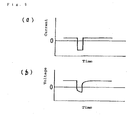
- the fourth invention among said inventions belonging to the first group is concerned with a process for manufacturing a printed circuit board which comprises disposing an interlayer resin insulating layer on a substrate formed with a conductor circuit, creating openings for formation of via holes in said interlayer resin insulating layer, forming an electroless plated metal layer on said interlayer resin insulating layer, disposing a resist thereon, performing electroplating, stripping the resist off and etching the electroless plated metal layer to provide a conductor circuit and via holes, wherein the electroplating is performed intermittently using said electroless plated metal layer as cathode and a plating metal as anode at a constant voltage between said anode and said cathode.
- the fifth invention among said inventions belonging to the second group is concerned with a printed circuit board comprising a resin insulating substrate board formed with a roughened surface and, as built thereon, a conductor circuit comprising at least an electroless plated film wherein that said electroless plated film has a stress of 0 to +10 kg/mm 2 .
- the above circuit comprises electrodes and mounting pads in addition to a conductor circuit pattern.
- the fourth invention among the inventions belonging to the first group is concerned with a process for producing a printed circuit board which comprises constructing an interlayer resin insulating layer on a conductor circuit-forming substrate board, forming openings for via holes in said interlayer resin insulating layer, forming an electroless plated metal layer over said interlayer resin insulating layer, disposing a resist thereon, performing electroplating, stripping the resist off and etching the electroless plated metal layer to form a conductor circuit pattern and via holes, wherein said electroplating is performed intermittently using said electroless plated metal layer as cathode and a plating metal as anode at a constant voltage between said anode and said cathode.
- This substrate is immersed in the electroplating solution and subjected to intermittent electroplating using the substrate as cathode and the plating metal as anode.
- thermosetting resin a thermoplastic resin, a partially photosensitized thermosetting resin, or a complex resin comprising thereof can be used.
- thermoplastic resin there can be used polyethersulfone (PES), polysulfone (PSF), polyphenylenesulfone (PPS), polyphenylene sulfide (PPES), polyphenyl ether (PPE), polyetherimide (PI) and fluororesin.
- PES polyethersulfone
- PPS polysulfone
- PPS polyphenylenesulfone
- PPES polyphenylene sulfide
- PPE polyphenyl ether
- PI polyetherimide
- fluororesin fluororesin.
- the preferred temperature of those electroless plating solutions is 25 to 40°C.
- the copper deposition rate of those electroless plating solutions is preferably 1 to 2 ⁇ m/hour.
- the third invention of the second group is concerned with an electroless plating process which comprises immersing a substrate in said electroless plating solution and performing copper electroless plating at the deposition rate set to 1 to 2 ⁇ m/hr as mentioned above.
- the first invention of the third group is concerned with a process for manufacturing a multilayer printed circuit board comprising at least the following steps (1) to (5).
- the core board may have been provided with plated-through holes.
- the difference between the thickness of the plated-through hole conductor and the thickness of the conductor circuit on the interlayer resin insulating layer is so small that an impedance alignment between the two conductors can be more easily attained.
- the thickness of said copper-clad laminate is preferably 0.5 to 1.0 mm. If the laminate is too thick, it cannot be neatly pierced, and if it is too thin, warpage tends to take place.
- the interlayer resin insulating layer can be formed with openings by means of a laser beam or by actinic light exposure and development.
- the deposited additive acts as a plating inhibitor to interfere with the deposition by electroplating. Therefore, the metal ion is preferentially precipitated in the openings for via holes in the course of electroplating, while the ion is harder to be deposited on the conductivity-imparted surface of the insulating layer. As a result, whereas the interiors of openings for via holes are filled up with the metal deposit, the thickness of the conductor circuit-forming metal film on the surface of the insulating layer is not increased as much. Thus, the filling of openings for via holes with the plating metal and the formation of a circuit board are concurrently achieved.
- the preferred opening for a vial hole with which the interlayer insulating layer is to be provided has an aspect ratio, i.e. the depth/diameter of the opening, of 1/3 to 1/1. If the aspect ratio is less than 1/3, the opening will be too large in diameter to fill up with the plating metal. On the other hand, if the aspect ratio exceeds 1/1, the metal ions will be hard to diffuse into the openings, resulting in a failure to fill up with the plating metal.
- the depth of the openings for via holes is preferably 10 to 100 ⁇ m. If the depth is less than 10 ⁇ m, the interlayer insulation will be too thin. If it exceeds 100 ⁇ m, the metal ions will not easily diffuse and those may not be supplied in a sufficient amount to fill up with the plating metal.
- the reason why said intermittent electroplating results in an increased crystallinity of the plated metal film is that every interruption of voltage application causes a diffusion of the metal ion near the interface of the surface being plated to insure a constant ion concentration so that a defect of the crystal lattice hardly occurs in the electrodeposited metal film.
- the layout density of plated-through holes in the multilayer core board can be increased, and because the wires can be consolidated at the same pace between the multilayer circuit stratum formed on the face side of the core board and the multilayer circuit stratum formed on the reverse side, the number of layers can be minimized by equating the number of layers of the upper-layer multilayer circuit stratum to the number of layers of the lower-layer multilayer circuit stratum. Furthermore, since the via hole is disposed immediately over the plated-through hole, the wiring length can be decreased to increase the signal transmission speed.
- the heat-resistant resin which is hardly soluble in an acid or an oxidizing agent, mentioned above, is preferably "a complex resin comprising a thermosetting resin and a thermoplastic resin” or "a complex resin comprising a photosensitive resin and a thermoplastic resin".
- the former is excellent in heat resistance, while the latter enables photolithographic formation of openings for via holes.
- thermoplastic resin can be the same resin as mentioned hereinbefore for the inventions of the first group.
- solder resist layer added to the surface of the multilayer printed circuit board a variety of resins can be used.
- resins can be used.
- bisphenol A epoxy resin, bisphenol A epoxy resin acrylate, novolac epoxy resin, and novolac epoxy resin acrylate cured with an amine series curing agent or an imidazole series curing agent can be mentioned.
- the epoxy resin obtainable by reacting a phenol novolac or cresol novolac glycidyl ether with acrylic acid or methacrylic acid, for instance, can be used.
- the photosensitive monomer mentioned above as an additive component includes polyfunctional acrylic monomers. This is because such polyfunctional acrylic monomers contribute to improving image resolution.
- polyfunctional acrylic monomers Nippon Kayaku's DPE-6A and Kyoeisha Kagaku's R-604 can be mentioned by way of example.
- the second invention of the sixth group is concerned with a multilayer printed circuit board comprising buildup wiring statum obtainable by building up an interlayer resin insulating layer and a conductor layer alternately, with each conductor layers being interconnected by via holes, as constructed on both sides of a core board wherein said core board has plated-through holes filled up with a filler and a conductor layer covering the surface of said filler which is exposed from the plated-through holes having lower-layer via holes, with upper-layer via holes being disposed just above said lower-layer via holes.
- the recesses in said lower-layer via holes are preferably filled with a conductive paste or resin.
- the heat-resistant resin which is hardly soluble in acid or oxidizing agent mentioned above is preferably "resin complex comprising a thermosetting resin and thermoplastic resin” or a “photosensitive resin-thermoplastic resin complex”. This is because the former is highly heat-resistant, while the latter has the advantage that openings for via holes can be formed by photolithography.
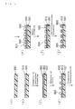
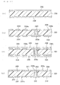
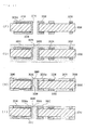
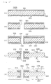
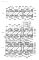
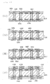
- Fig. 1 (a) to (g) show an exemplary process for fabricating the conductor circuit of the printed circuit board according to the invention
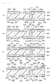
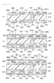
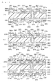
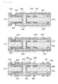
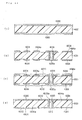
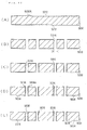
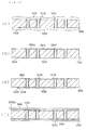
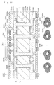
- Fig. 2 (a) to (e) show an exemplary process for manufacturing a multilayer printed circuit board in accordance with the invention.
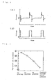
- Electroplated copper layers were built on 255 mm x 340 mm substrate sheets by depositing substantially uniform amounts of copper by 4 different electroplating techniques, namely direct-current plating, PC plating, PR plating and constant-voltage pulse plating techniques, using a copper sulfate plating solution containing 180 g/L of sulfuric acid and 80 g/L of copper sulfate under the conditions respectively indicated below in Table 1 to prepare printed circuit boards.
- the thickness of the electroplated copper layer of each board was measured in the central and marginal areas of substrate and the variation in thickness of the electroplated copper layer in the central and marginal areas of each board, i.e. [(maximum thickness-minimum thickness)/average thickness], was calculated to evaluate the electrodeposition uniformity.
- the plating substrate surface area, the composition of the constant-voltage pulse plating solution and the plating conditions are not particularly restricted but the following can be mentioned as preferred typical ranges.
- An IC wafer was fabricated by the well-known MOS wafer production technology, for example by the process described in LSI Process Engineering, pp. 22 to 23 [Published by Ohm-sha, K.K., June 20, 1987 ] [ Fig. 10 (a) ].
- the above substrate board was rinsed with water, acid-degreased, and soft-etched. Then, both sides of the substrate board are sprayed with an etching solution to etch the surface of the lower-layer conductor circuit 2004 and the land and inner wall surfaces of the plated-through holes 2009, thus forming roughened surfaces 2004a and 2009a over the whole surface of the lower-layer conductor circuit 2004 ( Fig. 12 (a) ) .
- the etching solution used was a mixture of 10 weight parts of imidazole copper (II) complex, 7 weight parts of glycolic acid, 5 weight parts of potassium chloride and 78 weight parts of deionized water.
- Example 1 The printed circuit boards thus fabricated in Example 1 and Comparative Example 1 were respectively allowed to sit in an environment of 121°C, 100% R.H., and 2 atmospheres for 168 hours to see whether the power source plain conductor layer (other than the mesh pattern) would develop blistering.
- the dry film resist ASAHI chemical, Co., AQ4059: not shown
- the resin filler C prepared in advance was applied to both sides of circuit substrate by roll coater to filled with the filler between conductor circuits and in the plated-through holes.
- the substrate was then subjected to heat treatment at 100°C for 1 hour, 120°C for 3 hours, 150°C for 1 hour and 180°C for 7 hours to cure the resin filler.
- the surface of the conductor circuit 3034 and the surface and lateral sides of land 3036a of plated-through holes 3036 are thus removed to make both sides of the substrate board flat and smooth.
- the resulting circuit board features a firm bond between the resin filler 3040 and roughened surface 3038 in the lateral sides of the inner-layer conductor circuit 3034 or roughened surface 3038 lateral sides of land 3036a of plated-through holes 3036 and between the resin filler 3040 and the lateral sides of plated-through holes.
- a roughened layer 3042 on the surfaces of the conductor circuit 3034 having a thickness of 3 ⁇ m was formed by roughing the surfaces of the conductor circuit 3034 and the surface and lateral sides of land 3036a of plated-through holes 3036 ( Fig.
- solder resist layer 3070 were printed with a solder paste followed by reflowing at 200°C to provide solder bumps (solder masses) 3076U, 3076D and thereby provide a multilayer printed circuit board 3010 ( Fig. 22 (U) ).
- the total thickness of copper foil 3031 and plated layer 3033 each constituting the conductor circuit 3034 becomes thinner so that the fine conductor circuit 3034 can be formed by patterned-etching mentioned above.
- Example 7 The process for the multilayer printed circuit board according to Example 7 is now described with reference to Fig. 26 .
- the process is same as Example 4, however as shown in Fig.26 (A) , conductor circuits 3034 and plated-through holes 3036 were formed in advance, and as shown in Fig.26 (B) , the only plated-through holes 3036 were followed by being filled with the resin filler 3040.
- the printed mask (not shown) which has the openings in the parts corresponding to plated-through holes was used for filling plated-through holes 3036.
- the surface was abraded ( Fig.26 (C) ) to provide the roughened layer 3042 comprising Cu-Ni-P on the surface of the conductor circuit as shown in Fig.26 (D) .
- a copper-clad laminate laminating a 18 ⁇ m-thick copper foil 4008 to both sides of a 1 mm-thick substrate 4001 having glass-epoxy resin or BT (bismaleimide-triazine) resin ( Fig. 28 (a) ).
- this copper-clad laminate was pierced with a drill, then the plated resist was formed, and electroless copper plating treatment was curried out to form plated-through holes 4009. Further, the copper foil was pattern-etched to form the inner-layer copper pattern in each side of the substrate (lower conductor circuit) 4004.
- the substrate thus formed with the inner-layer copper pattern 4004 was rinsed with water and dried.
- the substrate board completing the above-mentioned steps was immersed in an electroless nickel plating solution at 90 °C comprising nickel chloride (30 mol/L), sodium hypophosphite (10 mol/L), and sodium citrate (0.1 g/L) to provide 1.2 ⁇ m-thick nickel plated layer 4011a on the surface of the conductor circuit 4004 and the surface of the land of the plated-through hole 4009.
- an electroless nickel plating solution at 90 °C comprising nickel chloride (30 mol/L), sodium hypophosphite (10 mol/L), and sodium citrate (0.1 g/L) to provide 1.2 ⁇ m-thick nickel plated layer 4011a on the surface of the conductor circuit 4004 and the surface of the land of the plated-through hole 4009.
- 2 ⁇ m-thick Cu-Ni-P acicular alloy roughened layer 4011b was formed on the surfaces of the conductor circuit 4004 and lands of plated-through holes 4009 formed nickel plated layer 4011
- the roughened layer 4011b was formed by the following manner.
- the aspect ratio of said openings for via holes is 0.41.
- the substrate formed with openings for via holes 4006 was immersed in chromic acid (750 g/l) at 73°C for 20 minutes to dissolve and removed the epoxy resin particles from the surface of the interlayer resin insulating layer 4002 to roughen the surface, then immersed in a neutralizing solution (Shipley) and rinsed with water ( Fig. 29 (d) ). Then, a palladium catalyst (Atotech) was applied to the surface of the substrate board which had been subjected to surface roughening in the above step to deposit the catalyst nucleus on the surface of the interlayer resin insulating layer 4002 and inner side of openings for via holes 4006.
- chromic acid 750 g/l
- a neutralizing solution Shipley
- Fig. 29 (d) a palladium catalyst
- the multilayer printed circuit board was obtained as the same procedure as Example 8 except the concentration of thiourea 1.30 mmol/L.
- the multilayer printed circuit board was obtained as the same procedure as Example 8 except the concentration of thiourea 1.55 mmol/L.
- a curing composition was prepared by mixing and stirring 2 weight parts of imidazole series curing agent (Shikoku Kasei; 2E4MZ-CN), 2 weight parts of photopolymerization initiator (Ciba-Beigy; Irgacure I-907), 0.2 weight part of photosensitizer (Nippon Kayaku; DETX-S) and 1.5 weight parts of NMP.
- imidazole series curing agent Shikoku Kasei; 2E4MZ-CN
- photopolymerization initiator Ciba-Beigy; Irgacure I-907
- photosensitizer Nippon Kayaku; DETX-S
- Viscosity measurement was carried out with a Type B viscometer (Tokyo Keiki, DVL-B) using a rotor No. 4 for 60 rpm and a rotor No. 3 for 6 rpm.
- a commercial photosensitive dry film was pasted on the electroless plated copper film 5054 formed in the above step (14) and with a mask placed in position, exposure at 100 mJ/cm 2 and development with 0.8 % sodium carbonate were carried out to provide a 15 ⁇ m-thick plating photoresist 5054 ( Fig. 34 (M) ).
- the resist-free area was copper-electroplated under the following conditions to construct a 15 ⁇ m-thick copper electroplating layer 5056 (Fig. 34 (N)).
- Example 16 The process for manufacturing a multilayer printed circuit board according to Example 16 is now described with reference to Figs. 39 to 45 .
- the multilayer printed circuit board was fabricated by the semi-additive process.
- (1) As the starting material, a copper-clad laminate 6030A laminating a 18 ⁇ m-thick copper foil 6012 to both sides of a 0.5 mm-thick substrate 6030 having glass-epoxy resin or BT (bismaleimide-triazine) resin ( Fig. 39 (A) ).
- Etching resists were formed at the both sides thereof, etching treatment was curried out with an aqueous solution of sulfuric acid-hydrogen peroxide to provide the core board 6030 containing the conductor circuit 6014 ( Fig.
- the addition amount of the metal particles is preferably 30 to 90 wt.%. This is because the adhesion of cover plating becomes worse when the amount is less than 30 wt.%, while the printing efficiency becomes worse when the amount is over 90 wt.%.
- NMP normal methyl pyrrolidone
- DMDG diethylene glycol dimethyl ether
- glycerin water, 1-cicrohexanol, 2-cicrohexanol, 3-cicrohexanol, cicrohexanon, methyl cellsolve, methyl cellsolve acetate, methanol, ethanol, butanol, propanol.
- the non-conductive filler is preferably used. This is because the shrinkage caused by curing becomes small and the stripping between the conductor layer and via holes is hardly occurred when using the non-conductive filler.
- the metal surface-improving agents such as silane coupling agents may be used for improving the bond strength between the metal particle and resin.
- antiforming agents such as acryl type antiforming agent and silicone type antiforming agent
- inorganic fillers such as silica, alumina, talc
- Silane coupling agents may be also coated on the surface of the metal particle.
- fillers are printed in the following condition, for example.
- mask board of mesh board made of tetron and angle squeege with 45° of angle the printing is curried out under the condition of a Cu paste viscosity of 120 Pa ⁇ s, squeege speed at 13 mm/sec., and squeege depression of 1 mm.
- the roughened layer comprised of Cu-Ni-P alloy may be also formed by forming so-called blacken-reduction layer on the surface of the conductor layer 6026a covering the conductor circuit 6014a and the filler 6022, filling the resin such as bisphenol F type epoxy resin between the conductor circuits, abrading the surface, and plating of the above-mentioned (9). (10) The above-mentioned resin filler C.
- the resin composition 6028 prepared by the procedure described above in (10) was applied on both sides of the substrate board 6030 to fill the upper conducotor layer 6026a, to fill the lower conducotor layer 6026a or conductor circuit 6014a with the resin filler, and to be dried at 70°C for 20 minutes ( Fig. 41 (M) ).
- One side of the substrate board which had undergone the above procedure (11) was abraded with a belt sander using #600 belt sanding paper (Sankyo Rikagaku) to thoroughly remove the resin filler 6028 from the surface of the conducotor layer 6026a and the conductor circuit 6014a.
- the substrate board was heat-treated at 100°C for 1 hour, 120°C for 3 hours, 150°C for 1 hour and 180°C for 7 hours to cure the resin filler 6028. Since the roughened layer 6027 on the surface of the conductor layer 6026a and conductor circuit 6014a was removed and both sides of the surface was flattened, and then the resin filler 6028, the conductor layer 6026a and the lateral sides of the conductor circuit 6014a were firmly bonded via the roughened layer 5038.
- the electroless plating adhesive (upper-layer adhesive) was prepared by mixing and stirring the composition of the electroless plating adhesive A. and adjusting the viscosity of 7 Pa ⁇ s.
- the interlayer resin insulating agent (for the lower layer) 6044 with a viscosity of 1.5 Pa ⁇ s as obtained in (14) above was coated on both sides of the substrate of the above-mentioned (13) obtained above within 24 hours of preparation and the substrate board was allowed to sit in the horizontal position for 20 minutes and dried at 60°C for 30 minutes (prebake).
- the substrate 6030 was further exposed to light at 3000 mJ/cm 2 with the ultrahigh-pressure mercury arc lamp and heat-treated (postbaked) at 100°C for 1 hour, at 120°C for 1 hour and further at 150°C for 3 hours, whereby a 35 ⁇ m-thick interlayer resin insulating layer (binary structure) 6050 having 85 ⁇ m ⁇ openings (openings for via holes) 6048 with a good dimensional tolerance corresponding to that of the photomask film ( Fig. 42 (Q) ) was obtained.
- the plated tin layer (not shown) was caused to be partially exposed.
- the substrate board 6030 obtained in (24) above was coated in a thickness of 45 ⁇ m on both sides of the substrate board 6030 obtained in (24) above.
- a 5 mm-thick photomask film (not shown) carrying a pattern of dots (mask pattern) was placed in intimate contact and exposure with ultraviolet light at 1000 mJ/cm 2 and development with DMTG were carried out.
- the substrate board was further heat-treated at 80°C for 1 hour, at 100°C for 1 hour, at 120°C for 1 hour and at 150°C for 3 hours to provide a solder resist layer 6070 (thickness: 20 ⁇ m) having openings 6071 (opening dia.
- this board was immersed in an electroless gold plating solution containing 4.1x10 -2 mol/L of potassium cyanide-gold, 1.87x10 -1 mol/L of ammonium chloride, 1.16x10 -1 mol/L of sodium citrate and 1.7x10 -1 mol/L of sodium hypophosphite at 80% for 7 minutes and 20 seconds to provide a 0.03 ⁇ m plated gold layer 6074 on the plated nickel layer, whereby the via holes 6160 and conductor circuit 6158 were provided with solder pads 6075 ( Fig. 44 ).
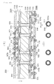
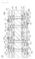
- solder resist layer 6070 were printed with a solder paste followed by reflowing at 200°C to provide solder bumps (solder masses) 6076U, 6076D and thereby provide a multilayer printed circuit board 6010 ( Fig. 44 ).
- the bumps 6076U of the multilayer printed circuit board 6010 were set in registration with the pads 6092 of an IC chip and caused to reflow to mount the IC chip 6092 on the multilayer printed circuit board 6010. Furthermore, the multilayer printed circuit board 6010 was mounted on a daughter board 6094 by setting it in registration with its pads 6096 and reflowing.
- the interlayer resin insulating layer 6050 having openings 6048 communicating with the lower-layer conductor layer 6026a can be electroless-plated to fill up the openings 6048 without application of an electroless plating catalyst. Since the pretreatment with an electroless plating catalyst is not performed in this case, the electroless plating metal is selectively deposited on the conductor layer 6026a in the bottom of the openings 6048. Therefore, the surface of this electroless plated conductor can be flat and smooth. It is also possible to form via holes 6060 by depositing an electroplating conductor on this electroless plated conductor having a flat surface.
- the covering plated layer (the conductor layer) 6026a was formed on the plated-through holes 6036 and the plated-through holes 6036 and via holes 6060 were interconnected via said conductor layer 6026a.
- via holes 6060 formed the through holes 6016 constituting the plated-through holes 6036 with the small diameter (100 to 200 ⁇ m) by laser were deposited at the position covering the through holes 6016 constituting the plated-through holes 6036, and lands 6036a in the plated-through holes 6036 and via holes 6060 were electro-connected.
- the laser processing equipment which can be used in this step includes a carbon dioxide gas laser equipment, a UV laser equipment and an eximer laser equipment.
- the preferred diameter is preferably 100 to 200 ⁇ m.
- the carbon dioxide gas laser equipment which features a high processing speed and a low-cost operation and, hence, is most suited for industrial use, is the laser processor of choice for the practice of the invention of the sixth group.
- Example 17 when 20 to 50 % of the bottom of via holes 6060 is connected lands 6036a in the plated-through holes 6036, the sufficient electrical connection thereof can be obtained.
- the lower via holes 6060 were formed on the plated-through holes 6036 and the upper via holes 6160 were formed on the lower via holes 6060, so that the plated-through holes 6036 and the upper via holes 6160 were deposited straight as a result the translation rate of an IC chip 6090 was improved.
- via holes 6060 filled via structure was used for via holes 6060.
- the surface of via holes 6060 was flattened to form the upper via holes 6160 by leaving concaved areas 6056a in the lower via holes 6060 and filling said concaved areas 6056a with the conductive pastes 6021.
- the multilayer printed circuit board according to Example 18 concaved areas 6056a in the lower via holes 6060 were filled with the conductive pastes 6021.
- the surface of via holes 6060 was flattened to form the upper via holes 6160 by filling said concaved areas 6056a in the lower via holes 6060 with the resin 6121.
- the multilayer printed circuit board according to Example 18 or 19 was produced more easily than that according to Example 16 or 17.
- solder bumps 6076U, 6076D were disposed at the position a little far from the plated-through holes 6036.
- solder bumps 6076U, 6076D were disposed immediately over the upper via holes 6160.
- the printed circuit boards according to the fifth through seventh inventions belonging to the second group are highly reliable because said electroless plating solution containing tartaric acid or a salt thereof yields an electroless plated metal film of good adhesion and high peel resistance on a roughened resin insulating layer as well as within via holes in a sufficient thickness.
Landscapes
- Chemical & Material Sciences (AREA)
- Engineering & Computer Science (AREA)
- Organic Chemistry (AREA)
- Chemical Kinetics & Catalysis (AREA)
- Materials Engineering (AREA)
- Metallurgy (AREA)
- Mechanical Engineering (AREA)
- Electrochemistry (AREA)
- General Chemical & Material Sciences (AREA)
- Manufacturing & Machinery (AREA)
- Microelectronics & Electronic Packaging (AREA)
- Crystallography & Structural Chemistry (AREA)
- Production Of Multi-Layered Print Wiring Board (AREA)
- Manufacturing Of Printed Wiring (AREA)
- Printing Elements For Providing Electric Connections Between Printed Circuits (AREA)
- Electroplating Methods And Accessories (AREA)
- Chemically Coating (AREA)
Applications Claiming Priority (9)
| Application Number | Priority Date | Filing Date | Title |
|---|---|---|---|
| JP25985498A JP4388611B2 (ja) | 1998-09-14 | 1998-09-14 | 銅被膜からなる配線を有するプリント配線板およびその製造方法、並びに銅被膜からなる回路を有する回路板 |
| JP28343598A JP2000101246A (ja) | 1998-09-17 | 1998-09-17 | 多層ビルドアップ配線板及び多層ビルドアップ配線板の製造方法 |
| JP28892598 | 1998-09-24 | ||
| JP33120098A JP4117951B2 (ja) | 1998-11-20 | 1998-11-20 | 多層プリント配線板の製造方法及び多層プリント配線板 |
| JP33449998A JP2000165046A (ja) | 1998-09-24 | 1998-11-25 | 多層ビルドアップ配線板 |
| JP36296298A JP4094143B2 (ja) | 1998-12-21 | 1998-12-21 | 多層プリント配線板の製造方法 |
| JP9591699A JP4236327B2 (ja) | 1999-04-02 | 1999-04-02 | 無電解めっき液、無電解めっき方法、プリント配線板の製造方法およびプリント配線板 |
| EP06003717A EP1667507B1 (fr) | 1998-09-14 | 1999-09-14 | Plaquette de circuit imprimé multicouche |
| EP99943326A EP1117283B1 (fr) | 1998-09-14 | 1999-09-14 | Plaquette de circuit imprime et son procede de fabrication |
Related Parent Applications (1)
| Application Number | Title | Priority Date | Filing Date |
|---|---|---|---|
| EP06003717A Division EP1667507B1 (fr) | 1998-09-14 | 1999-09-14 | Plaquette de circuit imprimé multicouche |
Publications (2)
| Publication Number | Publication Date |
|---|---|
| EP1923489A2 true EP1923489A2 (fr) | 2008-05-21 |
| EP1923489A3 EP1923489A3 (fr) | 2009-05-27 |
Family
ID=27565567
Family Applications (8)
| Application Number | Title | Priority Date | Filing Date |
|---|---|---|---|
| EP06003704A Expired - Lifetime EP1667504B1 (fr) | 1998-09-14 | 1999-09-14 | Procédé de fabrication d'une plaquette de circuit imprimé multicouche |
| EP08152453A Withdrawn EP1923488A3 (fr) | 1998-09-14 | 1999-09-14 | Procédé de fabrication d'une carte de circuit imprimé multicouche |
| EP06003705A Ceased EP1667505A1 (fr) | 1998-09-14 | 1999-09-14 | Plaquette de circuit imprime et son procede de fabrication |
| EP06003716A Expired - Lifetime EP1667506B1 (fr) | 1998-09-14 | 1999-09-14 | Procédé de placage anélectrolytique et plaquette de circuit imprimé |
| EP08150255A Withdrawn EP1919266A3 (fr) | 1998-09-14 | 1999-09-14 | Solution de placage anélectrolytique, processus de placage anélectrolytique, et carte de circuit imprimée |
| EP06003717A Expired - Lifetime EP1667507B1 (fr) | 1998-09-14 | 1999-09-14 | Plaquette de circuit imprimé multicouche |
| EP99943326A Expired - Lifetime EP1117283B1 (fr) | 1998-09-14 | 1999-09-14 | Plaquette de circuit imprime et son procede de fabrication |
| EP08152454A Withdrawn EP1923489A3 (fr) | 1998-09-14 | 1999-09-14 | Carte de circuit imprimé multicouche et son procédé de fabrication |
Family Applications Before (7)
| Application Number | Title | Priority Date | Filing Date |
|---|---|---|---|
| EP06003704A Expired - Lifetime EP1667504B1 (fr) | 1998-09-14 | 1999-09-14 | Procédé de fabrication d'une plaquette de circuit imprimé multicouche |
| EP08152453A Withdrawn EP1923488A3 (fr) | 1998-09-14 | 1999-09-14 | Procédé de fabrication d'une carte de circuit imprimé multicouche |
| EP06003705A Ceased EP1667505A1 (fr) | 1998-09-14 | 1999-09-14 | Plaquette de circuit imprime et son procede de fabrication |
| EP06003716A Expired - Lifetime EP1667506B1 (fr) | 1998-09-14 | 1999-09-14 | Procédé de placage anélectrolytique et plaquette de circuit imprimé |
| EP08150255A Withdrawn EP1919266A3 (fr) | 1998-09-14 | 1999-09-14 | Solution de placage anélectrolytique, processus de placage anélectrolytique, et carte de circuit imprimée |
| EP06003717A Expired - Lifetime EP1667507B1 (fr) | 1998-09-14 | 1999-09-14 | Plaquette de circuit imprimé multicouche |
| EP99943326A Expired - Lifetime EP1117283B1 (fr) | 1998-09-14 | 1999-09-14 | Plaquette de circuit imprime et son procede de fabrication |
Country Status (6)
| Country | Link |
|---|---|
| US (4) | US7230188B1 (fr) |
| EP (8) | EP1667504B1 (fr) |
| KR (1) | KR100815668B1 (fr) |
| DE (1) | DE69931272T2 (fr) |
| MY (4) | MY128333A (fr) |
| WO (1) | WO2000016597A1 (fr) |
Families Citing this family (196)
| Publication number | Priority date | Publication date | Assignee | Title |
|---|---|---|---|---|
| MY128333A (en) | 1998-09-14 | 2007-01-31 | Ibiden Co Ltd | Printed wiring board and its manufacturing method |
| JP3736607B2 (ja) * | 2000-01-21 | 2006-01-18 | セイコーエプソン株式会社 | 半導体装置及びその製造方法、回路基板並びに電子機器 |
| TW511405B (en) * | 2000-12-27 | 2002-11-21 | Matsushita Electric Industrial Co Ltd | Device built-in module and manufacturing method thereof |
| JP4148895B2 (ja) * | 2001-10-16 | 2008-09-10 | 新光電気工業株式会社 | ホールの銅めっき方法 |
| JP2006505919A (ja) * | 2002-02-26 | 2006-02-16 | レガシー エレクトロニクス, インコーポレイテッド | モジュール式集積回路チップキャリア |
| US6908784B1 (en) * | 2002-03-06 | 2005-06-21 | Micron Technology, Inc. | Method for fabricating encapsulated semiconductor components |
| CN101471323B (zh) * | 2002-08-09 | 2011-08-03 | 揖斐电株式会社 | 多层印刷线路板 |
| JP4488684B2 (ja) | 2002-08-09 | 2010-06-23 | イビデン株式会社 | 多層プリント配線板 |
| US20070090519A1 (en) * | 2003-05-01 | 2007-04-26 | Carter Antony A | Encased thermal management device and method of making such a device |
| KR100520961B1 (ko) * | 2003-05-30 | 2005-10-17 | 엘지전자 주식회사 | 인쇄회로기판의 제조방법 |
| US20040259375A1 (en) * | 2003-06-17 | 2004-12-23 | Derderian Garo J. | Removal of metal oxidation |
| KR101020164B1 (ko) | 2003-07-17 | 2011-03-08 | 허니웰 인터내셔날 인코포레이티드 | 진보된 마이크로전자적 응용을 위한 평탄화 막, 및 이를제조하기 위한 장치 및 방법 |
| JP4501861B2 (ja) * | 2003-09-29 | 2010-07-14 | 東レ株式会社 | チタンまたはチタン合金、接着用樹脂組成物、プリプレグおよび複合材料 |
| KR100557549B1 (ko) * | 2003-12-29 | 2006-03-03 | 삼성전기주식회사 | 플립칩 범프 패드 형성 방법 및 그 구조 |
| WO2005076682A1 (fr) * | 2004-02-04 | 2005-08-18 | Ibiden Co., Ltd. | Carte imprimee multicouche |
| US8338087B2 (en) * | 2004-03-03 | 2012-12-25 | Advanced Technology Materials, Inc | Composition and process for post-etch removal of photoresist and/or sacrificial anti-reflective material deposited on a substrate |
| TWI255491B (en) * | 2004-03-31 | 2006-05-21 | Sanyo Electric Co | Substrate for mounting elements, manufacturing method therefor and semiconductor device using the same |
| JP2005286273A (ja) * | 2004-03-31 | 2005-10-13 | Sohki:Kk | 回路基板、回路基板の製造方法、電子デバイス、電子デバイスの製造方法 |
| WO2005100641A1 (fr) * | 2004-04-15 | 2005-10-27 | Neomax Co., Ltd. | Procédé pour conférer une excellente résistance à l’hydrogène à un article et article démontrant une excellente résistance à l’hydrogène |
| DE602005022650D1 (de) | 2004-04-26 | 2010-09-16 | Rohm & Haas Elect Mat | Verbessertes Plattierungsverfahren |
| US20050251777A1 (en) * | 2004-05-05 | 2005-11-10 | International Business Machines Corporation | Method and structure for implementing enhanced electronic packaging and PCB layout with diagonal vias |
| GB2414864A (en) * | 2004-06-01 | 2005-12-07 | Nokia Corp | Detecting short circuits |
| CN100417313C (zh) * | 2004-06-29 | 2008-09-03 | 台湾吉德门国际股份有限公司 | 提升电路板制程良率的方法 |
| JP2006049804A (ja) * | 2004-07-07 | 2006-02-16 | Shinko Electric Ind Co Ltd | 配線基板の製造方法 |
| JP4992428B2 (ja) * | 2004-09-24 | 2012-08-08 | イビデン株式会社 | めっき方法及びめっき装置 |
| FI20041525A7 (fi) * | 2004-11-26 | 2006-03-17 | Imbera Electronics Oy | Elektroniikkamoduuli ja menetelmä sen valmistamiseksi |
| JP4819033B2 (ja) * | 2005-01-27 | 2011-11-16 | パナソニック株式会社 | 多層回路基板の製造方法 |
| JP2006216711A (ja) * | 2005-02-02 | 2006-08-17 | Ibiden Co Ltd | 多層プリント配線板 |
| JP2006216714A (ja) | 2005-02-02 | 2006-08-17 | Ibiden Co Ltd | 多層プリント配線板 |
| JP2006216713A (ja) * | 2005-02-02 | 2006-08-17 | Ibiden Co Ltd | 多層プリント配線板 |
| US7237334B2 (en) * | 2005-08-18 | 2007-07-03 | Intel Corporation | Method of providing a printed circuit board using laser assisted metallization and patterning of a microelectronic substrate |
| TWI275186B (en) * | 2005-10-17 | 2007-03-01 | Phoenix Prec Technology Corp | Method for manufacturing semiconductor package |
| US7570082B2 (en) * | 2006-08-15 | 2009-08-04 | International Business Machines Corporation | Voltage comparator apparatus and method having improved kickback and jitter characteristics |
| KR100879794B1 (ko) * | 2006-12-22 | 2009-01-22 | 삼성전기주식회사 | 진동모터용 정류자, 진동모터 및 이에 사용되는 도금액 |
| JP4840132B2 (ja) * | 2006-12-26 | 2011-12-21 | 株式会社デンソー | 多層基板の製造方法 |
| JP4902558B2 (ja) * | 2007-01-31 | 2012-03-21 | 三洋電機株式会社 | 半導体モジュールの製造方法 |
| EP2113038B1 (fr) * | 2007-02-20 | 2011-12-21 | Dynamic Details, Inc. | Cartes de câblage imprime multicouche avec des trous débouchants remplis de cuivre |
| JP2008218552A (ja) * | 2007-03-01 | 2008-09-18 | Nec Corp | 電子部品の実装基板および実装方法 |
| JP4383487B2 (ja) * | 2007-03-19 | 2009-12-16 | 古河電気工業株式会社 | 金属張積層体及び金属張積層体の製造方法 |
| US7969005B2 (en) * | 2007-04-27 | 2011-06-28 | Sanyo Electric Co., Ltd. | Packaging board, rewiring, roughened conductor for semiconductor module of a portable device, and manufacturing method therefor |
| US20080271995A1 (en) * | 2007-05-03 | 2008-11-06 | Sergey Savastiouk | Agitation of electrolytic solution in electrodeposition |
| TW200906263A (en) * | 2007-05-29 | 2009-02-01 | Matsushita Electric Industrial Co Ltd | Circuit board and method for manufacturing the same |
| US7923645B1 (en) * | 2007-06-20 | 2011-04-12 | Amkor Technology, Inc. | Metal etch stop fabrication method and structure |
| US8877565B2 (en) * | 2007-06-28 | 2014-11-04 | Intel Corporation | Method of forming a multilayer substrate core structure using sequential microvia laser drilling and substrate core structure formed according to the method |
| US8440916B2 (en) * | 2007-06-28 | 2013-05-14 | Intel Corporation | Method of forming a substrate core structure using microvia laser drilling and conductive layer pre-patterning and substrate core structure formed according to the method |
| WO2009008066A1 (fr) * | 2007-07-10 | 2009-01-15 | Ibiden Co., Ltd. | Substrat de câblage, et son procédé de fabrication |
| KR100841987B1 (ko) * | 2007-07-10 | 2008-06-27 | 삼성전기주식회사 | 다층 인쇄회로기판 제조방법 |
| US8044306B2 (en) | 2007-07-11 | 2011-10-25 | Ibiden Co., Ltd. | Wiring board and method of manufacturing the same |
| US8192815B2 (en) | 2007-07-13 | 2012-06-05 | Apple Inc. | Methods and systems for forming a dual layer housing |
| WO2009045316A1 (fr) * | 2007-10-03 | 2009-04-09 | Sifco Selective Plating | Procédé de plaquage de métal sur du titane |
| US8112884B2 (en) * | 2007-10-08 | 2012-02-14 | Honeywell International Inc. | Method for providing an efficient thermal transfer through a printed circuit board |
| JP2009099624A (ja) * | 2007-10-12 | 2009-05-07 | Fujitsu Ltd | 配線基板およびその製造方法 |
| TWI450666B (zh) * | 2007-11-22 | 2014-08-21 | Ajinomoto Kk | 多層印刷配線板之製造方法及多層印刷配線板 |
| KR20090067249A (ko) * | 2007-12-21 | 2009-06-25 | 삼성전기주식회사 | 인쇄회로기판 및 그 제조방법 |
| KR101070798B1 (ko) * | 2008-01-15 | 2011-10-06 | 삼성전기주식회사 | 인쇄회로기판 및 그 제조방법 |
| US8315043B2 (en) * | 2008-01-24 | 2012-11-20 | Apple Inc. | Methods and systems for forming housings from multi-layer materials |
| US8007286B1 (en) | 2008-03-18 | 2011-08-30 | Metrospec Technology, Llc | Circuit boards interconnected by overlapping plated through holes portions |
| US11266014B2 (en) | 2008-02-14 | 2022-03-01 | Metrospec Technology, L.L.C. | LED lighting systems and method |
| US8851356B1 (en) | 2008-02-14 | 2014-10-07 | Metrospec Technology, L.L.C. | Flexible circuit board interconnection and methods |
| US8143631B2 (en) | 2008-03-06 | 2012-03-27 | Metrospec Technology Llc | Layered structure for use with high power light emitting diode systems |
| US10334735B2 (en) | 2008-02-14 | 2019-06-25 | Metrospec Technology, L.L.C. | LED lighting systems and methods |
| US8646637B2 (en) * | 2008-04-18 | 2014-02-11 | Apple Inc. | Perforated substrates for forming housings |
| US20090289032A1 (en) * | 2008-05-23 | 2009-11-26 | General Electric Company | Method and kit for surface preparation |
| US8367304B2 (en) | 2008-06-08 | 2013-02-05 | Apple Inc. | Techniques for marking product housings |
| JPWO2010013611A1 (ja) * | 2008-07-30 | 2012-01-12 | 住友ベークライト株式会社 | 無電解銅メッキ方法、プリント配線板、プリント配線板製造方法、半導体装置 |
| US8132321B2 (en) * | 2008-08-13 | 2012-03-13 | Unimicron Technology Corp. | Method for making embedded circuit structure |
| US7776741B2 (en) * | 2008-08-18 | 2010-08-17 | Novellus Systems, Inc. | Process for through silicon via filing |
| US7943862B2 (en) * | 2008-08-20 | 2011-05-17 | Electro Scientific Industries, Inc. | Method and apparatus for optically transparent via filling |
| US20100090339A1 (en) * | 2008-09-12 | 2010-04-15 | Kumar Ananda H | Structures and Methods for Wafer Packages, and Probes |
| EP2200413A4 (fr) * | 2008-09-30 | 2011-12-14 | Ibiden Co Ltd | Carte de circuit imprimé à couches multiples et procédé de fabrication de carte de circuit imprimé à couches multiples |
| KR100990546B1 (ko) * | 2008-12-08 | 2010-10-29 | 삼성전기주식회사 | 비아 단부에 매립된 도금패턴을 갖는 인쇄회로기판 및 이의제조방법 |
| US20100159273A1 (en) | 2008-12-24 | 2010-06-24 | John Benjamin Filson | Method and Apparatus for Forming a Layered Metal Structure with an Anodized Surface |
| US7811918B1 (en) * | 2009-01-09 | 2010-10-12 | The United States Of America As Represented By The Secretary Of The Navy | Electric current induced liquid metal flow and metallic conformal coating of conductive templates |
| US8592691B2 (en) * | 2009-02-27 | 2013-11-26 | Ibiden Co., Ltd. | Printed wiring board |
| JP2010238691A (ja) * | 2009-03-30 | 2010-10-21 | Fujitsu Ltd | 中継部材およびプリント基板ユニット |
| WO2010113539A1 (fr) * | 2009-04-02 | 2010-10-07 | 株式会社村田製作所 | Carte de circuits imprimés |
| US8513792B2 (en) * | 2009-04-10 | 2013-08-20 | Intel Corporation | Package-on-package interconnect stiffener |
| KR20120003458A (ko) * | 2009-04-24 | 2012-01-10 | 스미토모 덴키 고교 가부시키가이샤 | 프린트 배선판용 기판, 프린트 배선판, 및 그들의 제조방법 |
| US9884342B2 (en) | 2009-05-19 | 2018-02-06 | Apple Inc. | Techniques for marking product housings |
| US9173336B2 (en) | 2009-05-19 | 2015-10-27 | Apple Inc. | Techniques for marking product housings |
| US8426959B2 (en) * | 2009-08-19 | 2013-04-23 | Samsung Electronics Co., Ltd. | Semiconductor package and method of manufacturing the same |
| US8663806B2 (en) | 2009-08-25 | 2014-03-04 | Apple Inc. | Techniques for marking a substrate using a physical vapor deposition material |
| JP5428667B2 (ja) * | 2009-09-07 | 2014-02-26 | 日立化成株式会社 | 半導体チップ搭載用基板の製造方法 |
| US9109295B2 (en) * | 2009-10-12 | 2015-08-18 | Novellus Systems, Inc. | Electrolyte concentration control system for high rate electroplating |
| US10472730B2 (en) | 2009-10-12 | 2019-11-12 | Novellus Systems, Inc. | Electrolyte concentration control system for high rate electroplating |
| US20110089039A1 (en) * | 2009-10-16 | 2011-04-21 | Michael Nashner | Sub-Surface Marking of Product Housings |
| US10071583B2 (en) * | 2009-10-16 | 2018-09-11 | Apple Inc. | Marking of product housings |
| US8809733B2 (en) * | 2009-10-16 | 2014-08-19 | Apple Inc. | Sub-surface marking of product housings |
| US9845546B2 (en) | 2009-10-16 | 2017-12-19 | Apple Inc. | Sub-surface marking of product housings |
| JP2011096900A (ja) * | 2009-10-30 | 2011-05-12 | Fujitsu Ltd | 導電体およびプリント配線板並びにそれらの製造方法 |
| US8929092B2 (en) | 2009-10-30 | 2015-01-06 | Panasonic Corporation | Circuit board, and semiconductor device having component mounted on circuit board |
| US9332642B2 (en) * | 2009-10-30 | 2016-05-03 | Panasonic Corporation | Circuit board |
| KR101089986B1 (ko) * | 2009-12-24 | 2011-12-05 | 삼성전기주식회사 | 캐리어기판, 그의 제조방법, 이를 이용한 인쇄회로기판 및 그의 제조방법 |
| EP2525633A4 (fr) * | 2010-01-15 | 2013-07-03 | Jx Nippon Mining & Metals Corp | Circuit électronique, procédé de fabrication de celui-ci, et stratifié gainé de cuivre pour fabrication de circuit électronique |
| US8628836B2 (en) * | 2010-03-02 | 2014-01-14 | Apple Inc. | Method and apparatus for bonding metals and composites |
| US8489158B2 (en) | 2010-04-19 | 2013-07-16 | Apple Inc. | Techniques for marking translucent product housings |
| JP2011243790A (ja) * | 2010-05-19 | 2011-12-01 | Panasonic Electric Works Co Ltd | 配線方法、並びに、表面に配線が設けられた構造物、半導体装置、配線基板、メモリカード、電気デバイス、モジュール及び多層回路基板 |
| KR20110139462A (ko) * | 2010-06-23 | 2011-12-29 | 삼성전기주식회사 | 절연수지 조성물 및 이를 이용하여 제조된 인쇄회로기판 |
| US8518826B2 (en) | 2010-07-13 | 2013-08-27 | Lam Research Corporation | Metallization processes, mixtures, and electronic devices |
| TWI436713B (zh) * | 2010-07-26 | 2014-05-01 | Via Tech Inc | 線路基板、線路基板製程 |
| US8947892B1 (en) * | 2010-08-16 | 2015-02-03 | The Boeing Company | Electronic device protection |
| US8847380B2 (en) * | 2010-09-17 | 2014-09-30 | Tessera, Inc. | Staged via formation from both sides of chip |
| US8756803B2 (en) * | 2010-09-22 | 2014-06-24 | Ibiden Co., Ltd. | Method for manufacturing printed wiring board |
| US9545043B1 (en) * | 2010-09-28 | 2017-01-10 | Rockwell Collins, Inc. | Shielding encapsulation for electrical circuitry |
| US8724285B2 (en) | 2010-09-30 | 2014-05-13 | Apple Inc. | Cosmetic conductive laser etching |
| JP5602584B2 (ja) * | 2010-10-28 | 2014-10-08 | 新光電気工業株式会社 | 配線基板及びその製造方法 |
| DE102011011139B4 (de) * | 2011-02-14 | 2023-01-19 | Osram Opto Semiconductors Gmbh | Verfahren zur Herstellung zumindest eines optoelektronischen Halbleiterbauelements und optoelektronisches Halbleiterbauelement |
| JP2012174758A (ja) * | 2011-02-18 | 2012-09-10 | Fujifilm Corp | 多層基板の製造方法、デスミア処理方法 |
| US20120248001A1 (en) | 2011-03-29 | 2012-10-04 | Nashner Michael S | Marking of Fabric Carrying Case for Portable Electronic Device |
| US9280183B2 (en) | 2011-04-01 | 2016-03-08 | Apple Inc. | Advanced techniques for bonding metal to plastic |
| CN102892252B (zh) * | 2011-07-19 | 2015-08-05 | 联滔电子有限公司 | 三维电路的制造方法 |
| TWI445474B (zh) * | 2011-11-18 | 2014-07-11 | Chuan Ling Hu | Manufacturing method of plastic metallized three - dimensional line |
| US9117730B2 (en) * | 2011-12-29 | 2015-08-25 | Ibiden Co., Ltd. | Printed wiring board and method for manufacturing printed wiring board |
| US8879266B2 (en) * | 2012-05-24 | 2014-11-04 | Apple Inc. | Thin multi-layered structures providing rigidity and conductivity |
| US10071584B2 (en) | 2012-07-09 | 2018-09-11 | Apple Inc. | Process for creating sub-surface marking on plastic parts |
| KR101992352B1 (ko) * | 2012-09-25 | 2019-06-24 | 삼성전자주식회사 | 반도체 장치 |
| CN103717009A (zh) * | 2012-10-08 | 2014-04-09 | 苏州卓融水处理科技有限公司 | 一种无核封装基板种子层附着力的方法 |
| JP5352748B1 (ja) * | 2012-10-26 | 2013-11-27 | Jx日鉱日石金属株式会社 | キャリア付銅箔、それを用いた銅張積層板、プリント配線板、プリント回路板、及び、プリント配線板の製造方法 |
| JP5358739B1 (ja) * | 2012-10-26 | 2013-12-04 | Jx日鉱日石金属株式会社 | キャリア付銅箔、それを用いた銅張積層板、プリント配線板、プリント回路板、及び、プリント配線板の製造方法 |
| TWI449620B (zh) * | 2012-11-20 | 2014-08-21 | 國立臺灣科技大學 | 鎳/銦/錫/銅多層結構之製造方法 |
| EP3147916A1 (fr) * | 2012-12-19 | 2017-03-29 | Telefonaktiebolaget LM Ericsson (PUBL) | Procédé de fabrication d'un transformateur pcb planaire |
| US9312222B2 (en) * | 2013-03-12 | 2016-04-12 | Taiwan Semiconductor Manufacturing Co., Ltd. | Patterning approach for improved via landing profile |
| US9434197B2 (en) | 2013-06-18 | 2016-09-06 | Apple Inc. | Laser engraved reflective surface structures |
| US9314871B2 (en) | 2013-06-18 | 2016-04-19 | Apple Inc. | Method for laser engraved reflective surface structures |
| JP6266907B2 (ja) * | 2013-07-03 | 2018-01-24 | 新光電気工業株式会社 | 配線基板及び配線基板の製造方法 |
| US9663867B2 (en) * | 2013-07-15 | 2017-05-30 | United Technologies Corporation | Plated instrumentation probes and sensors |
| CN103429012B (zh) * | 2013-08-02 | 2016-01-13 | 北大方正集团有限公司 | 一种pcb板上的背钻孔的制备方法以及pcb板 |
| CN104349609A (zh) * | 2013-08-08 | 2015-02-11 | 北大方正集团有限公司 | 印刷线路板及其制作方法 |
| KR101548421B1 (ko) * | 2013-08-27 | 2015-08-28 | 삼성전기주식회사 | 다층인쇄회로기판의 제조방법 |
| WO2015141769A1 (fr) | 2014-03-20 | 2015-09-24 | 住友電気工業株式会社 | Substrat pour carte de câblage imprimé, carte de câblage imprimé et procédé de fabrication de substrat pour carte de câblage imprimé |
| WO2015147219A1 (fr) | 2014-03-27 | 2015-10-01 | 住友電気工業株式会社 | Substrat pour cartes de circuits imprimés, carte de circuits imprimés et procédé de fabrication de substrat pour cartes de circuits imprimés |
| JP2015213124A (ja) * | 2014-05-02 | 2015-11-26 | イビデン株式会社 | パッケージ基板 |
| US9398703B2 (en) * | 2014-05-19 | 2016-07-19 | Sierra Circuits, Inc. | Via in a printed circuit board |
| JP5823005B1 (ja) * | 2014-08-29 | 2015-11-25 | Jx日鉱日石金属株式会社 | キャリア付銅箔の製造方法、銅張積層板の製造方法、プリント配線板の製造方法、及び、電子機器及びキャリア付銅箔 |
| DE102014218300B3 (de) * | 2014-09-12 | 2016-01-07 | Evonik Degussa Gmbh | Verfahren zur Herstellung strukturierter Beschichtungen, strukturierte Beschichtung und ihre Verwendung |
| JP6585434B2 (ja) * | 2014-10-06 | 2019-10-02 | 株式会社荏原製作所 | めっき方法 |
| US10154598B2 (en) | 2014-10-13 | 2018-12-11 | Rohm And Haas Electronic Materials Llc | Filling through-holes |
| US9433101B2 (en) * | 2014-10-16 | 2016-08-30 | International Business Machines Corporation | Substrate via filling |
| CN105657988B (zh) * | 2014-11-21 | 2019-04-23 | 宏启胜精密电子(秦皇岛)有限公司 | 柔性电路板及其制作方法 |
| US10076028B2 (en) | 2015-01-22 | 2018-09-11 | Sumitomo Electric Industries, Ltd. | Substrate for printed circuit board, printed circuit board, and method for producing printed circuit board |
| JP6328575B2 (ja) * | 2015-02-23 | 2018-05-23 | 東京エレクトロン株式会社 | 触媒層形成方法、触媒層形成システムおよび記憶媒体 |
| JP6641717B2 (ja) * | 2015-04-08 | 2020-02-05 | 日立化成株式会社 | 多層配線基板の製造方法 |
| CN104812179B (zh) * | 2015-04-21 | 2017-12-01 | 深圳崇达多层线路板有限公司 | 一种印刷电路板的孔铜制备工艺及印刷电路板 |
| US10182499B2 (en) * | 2015-11-09 | 2019-01-15 | The University Of Memphis Research Foundation | Multilayer additive printed circuit |
| WO2017090161A1 (fr) * | 2015-11-26 | 2017-06-01 | 近藤 和夫 | Solution de cuivrage acide, produit à cuivrage acide, et procédé de fabrication de dispositif à semi-conducteurs |
| JP2018165375A (ja) * | 2015-11-26 | 2018-10-25 | 近藤 和夫 | 酸性銅めっき液、酸性銅めっき物および半導体デバイスの製造方法 |
| JP2017136711A (ja) * | 2016-02-02 | 2017-08-10 | セイコーエプソン株式会社 | 配線基板、memsデバイス、液体噴射ヘッド及び液体噴射装置 |
| US10519557B2 (en) | 2016-02-12 | 2019-12-31 | Macdermid Enthone Inc. | Leveler compositions for use in copper deposition in manufacture of microelectronics |
| CN105721749B (zh) * | 2016-02-24 | 2020-07-24 | 宁波舜宇光电信息有限公司 | 摄像模组及其电气支架和线路板组件及制造方法 |
| US10487410B2 (en) | 2016-02-26 | 2019-11-26 | Applied Materials, Inc. | Enhanced plating bath and additive chemistries for cobalt plating |
| CN117241501A (zh) * | 2016-07-01 | 2023-12-15 | 三菱瓦斯化学株式会社 | 半导体元件搭载用封装体基板的制造方法和半导体元件安装基板的制造方法 |
| US10849233B2 (en) | 2017-07-10 | 2020-11-24 | Catlam, Llc | Process for forming traces on a catalytic laminate |
| US10349520B2 (en) | 2017-06-28 | 2019-07-09 | Catlam, Llc | Multi-layer circuit board using interposer layer and conductive paste |
| US10765012B2 (en) | 2017-07-10 | 2020-09-01 | Catlam, Llc | Process for printed circuit boards using backing foil |
| US10692735B2 (en) | 2017-07-28 | 2020-06-23 | Lam Research Corporation | Electro-oxidative metal removal in through mask interconnect fabrication |
| US20200006135A1 (en) * | 2017-07-31 | 2020-01-02 | At&S Austria Technologie & Systemtechnik Aktiengesellschaft | Method and Plater Arrangement for Failure-Free Copper Filling of a Hole in a Component Carrier |
| KR102069659B1 (ko) | 2017-08-31 | 2020-01-23 | 해성디에스 주식회사 | 반도체 패키지 기판 제조방법 및 이를 이용하여 제조된 반도체 패키지 기판 |
| US10827624B2 (en) | 2018-03-05 | 2020-11-03 | Catlam, Llc | Catalytic laminate with conductive traces formed during lamination |
| WO2019171990A1 (fr) * | 2018-03-09 | 2019-09-12 | 株式会社有沢製作所 | Stratifié, et procédé de fabrication de celui-ci |
| US10999917B2 (en) | 2018-09-20 | 2021-05-04 | Apple Inc. | Sparse laser etch anodized surface for cosmetic grounding |
| US10849200B2 (en) | 2018-09-28 | 2020-11-24 | Metrospec Technology, L.L.C. | Solid state lighting circuit with current bias and method of controlling thereof |
| CN109729639B (zh) * | 2018-12-24 | 2020-11-20 | 奥特斯科技(重庆)有限公司 | 在无芯基板上包括柱体的部件承载件 |
| US11342256B2 (en) * | 2019-01-24 | 2022-05-24 | Applied Materials, Inc. | Method of fine redistribution interconnect formation for advanced packaging applications |
| US10903157B2 (en) * | 2019-03-08 | 2021-01-26 | Skc Co., Ltd. | Semiconductor device having a glass substrate core layer |
| WO2020215225A1 (fr) * | 2019-04-23 | 2020-10-29 | 庆鼎精密电子(淮安)有限公司 | Carte de circuit imprimé et son procédé de fabrication |
| IT201900006736A1 (it) | 2019-05-10 | 2020-11-10 | Applied Materials Inc | Procedimenti di fabbricazione di package |
| IT201900006740A1 (it) | 2019-05-10 | 2020-11-10 | Applied Materials Inc | Procedimenti di strutturazione di substrati |
| US11931855B2 (en) | 2019-06-17 | 2024-03-19 | Applied Materials, Inc. | Planarization methods for packaging substrates |
| CN112312671B (zh) * | 2019-07-30 | 2024-03-12 | 宏恒胜电子科技(淮安)有限公司 | 电路板以及电路板的制备方法 |
| JP2022545091A (ja) * | 2019-08-19 | 2022-10-25 | アトテック ドイチェランド ゲーエムベーハー ウント コ カーゲー | 銅で充填されたマイクロビアを含む高密度相互接続プリント回路基板の製造方法 |
| CN112752429B (zh) * | 2019-10-31 | 2022-08-16 | 鹏鼎控股(深圳)股份有限公司 | 多层线路板及其制作方法 |
| US11862546B2 (en) | 2019-11-27 | 2024-01-02 | Applied Materials, Inc. | Package core assembly and fabrication methods |
| US11257790B2 (en) | 2020-03-10 | 2022-02-22 | Applied Materials, Inc. | High connectivity device stacking |
| US11454884B2 (en) | 2020-04-15 | 2022-09-27 | Applied Materials, Inc. | Fluoropolymer stamp fabrication method |
| US11488901B2 (en) * | 2020-04-29 | 2022-11-01 | Advanced Semiconductor Engineering, Inc. | Package structure and method for manufacturing the same |
| US11400545B2 (en) | 2020-05-11 | 2022-08-02 | Applied Materials, Inc. | Laser ablation for package fabrication |
| US11232951B1 (en) | 2020-07-14 | 2022-01-25 | Applied Materials, Inc. | Method and apparatus for laser drilling blind vias |
| US11676832B2 (en) | 2020-07-24 | 2023-06-13 | Applied Materials, Inc. | Laser ablation system for package fabrication |
| US11393747B2 (en) * | 2020-08-31 | 2022-07-19 | Advanced Semiconductor Engineering, Inc. | Substrate structure having roughned upper surface of conductive layer |
| KR102902121B1 (ko) * | 2020-09-03 | 2025-12-19 | 엘지이노텍 주식회사 | 회로기판 |
| US12016128B2 (en) | 2020-09-03 | 2024-06-18 | Lg Innotek Co., Ltd. | Circuit board and method of manufacturing the same |
| US11692049B2 (en) | 2020-09-18 | 2023-07-04 | Ford Global Technologies, Llc | Additively manufactured thermoset polymers for metal plating and metal plated parts formed therefrom |
| KR102903533B1 (ko) * | 2020-09-28 | 2025-12-22 | 푸?? 징안 옵토일렉트로닉스 컴퍼니 리미티드 | 웨이퍼의 흑화 방법, 흑화된 웨이퍼 및 탄성 표면파 필터 |
| US11521937B2 (en) | 2020-11-16 | 2022-12-06 | Applied Materials, Inc. | Package structures with built-in EMI shielding |
| US11404318B2 (en) | 2020-11-20 | 2022-08-02 | Applied Materials, Inc. | Methods of forming through-silicon vias in substrates for advanced packaging |
| CN112739022A (zh) * | 2020-12-22 | 2021-04-30 | 江西志博信科技股份有限公司 | 一种hdi技术应用印刷电路板的工艺 |
| CN113267659B (zh) * | 2021-05-18 | 2024-06-21 | 上海泽丰半导体科技有限公司 | Ate测试板及ate测试板的制造方法 |
| US11705365B2 (en) | 2021-05-18 | 2023-07-18 | Applied Materials, Inc. | Methods of micro-via formation for advanced packaging |
| US12324114B2 (en) | 2021-09-24 | 2025-06-03 | Apple Inc. | Laser-marked electronic device housings |
| CN114007343B (zh) * | 2021-10-22 | 2024-05-17 | 深圳明阳电路科技股份有限公司 | 一种印刷电路板电厚金、印刷电路板及其制造方法 |
| US12183684B2 (en) | 2021-10-26 | 2024-12-31 | Applied Materials, Inc. | Semiconductor device packaging methods |
| CN118511660A (zh) * | 2022-01-04 | 2024-08-16 | 住友电气工业株式会社 | 印刷布线板 |
| CN114678208B (zh) * | 2022-04-02 | 2023-06-20 | 电子科技大学 | 一种全树脂片式电感的制作方法 |
| WO2023201117A2 (fr) * | 2022-04-15 | 2023-10-19 | Atlas Magnetics Incorporated. | Procédé et appareil pour un nouveau matériau à base de métal conducteur haute performance |
| JP2023179281A (ja) * | 2022-06-07 | 2023-12-19 | イビデン株式会社 | 配線基板 |
| WO2026010891A1 (fr) * | 2024-06-28 | 2026-01-08 | Atlas Magnetics | Résistance hybride à couches d'isolation hybrides orientées |
Citations (9)
| Publication number | Priority date | Publication date | Assignee | Title |
|---|---|---|---|---|
| JPS493833A (fr) | 1972-05-04 | 1974-01-14 | ||
| JPS57116799A (en) | 1981-01-09 | 1982-07-20 | Kobe Steel Ltd | Method for copper plating |
| JPS628514A (ja) | 1985-07-05 | 1987-01-16 | 昭和電工株式会社 | 電解コンデンサ− |
| JPS63158156A (ja) | 1987-07-31 | 1988-07-01 | Konpon:Kk | カレンダ−ロ−ルを用いた高粘度樹脂シ−トの製造方法及びその装置 |
| JPH0222887A (ja) | 1988-07-12 | 1990-01-25 | Mitsubishi Gas Chem Co Inc | 薄銅箔張回路基板の製造法 |
| JPH02188992A (ja) | 1989-01-18 | 1990-07-25 | Ibiden Co Ltd | 多層プリント配線板およびその製造方法 |
| US5055321A (en) | 1988-04-28 | 1991-10-08 | Ibiden Co., Ltd. | Adhesive for electroless plating, printed circuit boards and method of producing the same |
| JPH0455555A (ja) | 1990-06-25 | 1992-02-24 | Misawa Homes Co Ltd | 建物の手摺支柱の設置構造 |
| US5519177A (en) | 1993-05-19 | 1996-05-21 | Ibiden Co., Ltd. | Adhesives, adhesive layers for electroless plating and printed circuit boards |
Family Cites Families (93)
| Publication number | Priority date | Publication date | Assignee | Title |
|---|---|---|---|---|
| DE1163114B (de) * | 1962-02-13 | 1964-02-13 | Dehydag Gmbh | Galvanische Metallbaeder |
| US3322881A (en) * | 1964-08-19 | 1967-05-30 | Jr Frederick W Schneble | Multilayer printed circuit assemblies |
| US3350498A (en) * | 1965-01-04 | 1967-10-31 | Intellux Inc | Multilayer circuit and method of making the same |
| CH422933A (fr) * | 1965-03-12 | 1966-10-31 | Gen Protection Establishment | Paratonnerre à grande puissance ionisante |
| GB1288992A (fr) * | 1970-06-22 | 1972-09-13 | ||
| US3716462A (en) | 1970-10-05 | 1973-02-13 | D Jensen | Copper plating on zinc and its alloys |
| JPS547267B2 (fr) | 1973-09-21 | 1979-04-05 | ||
| NL7402422A (nl) | 1974-02-22 | 1975-08-26 | Philips Nv | Universele verkoperingsoplossing. |
| US3977884A (en) | 1975-01-02 | 1976-08-31 | Shipley Company, Inc. | Metal plating solution |
| JPS574116B2 (fr) | 1975-02-07 | 1982-01-25 | ||
| US4265943A (en) | 1978-11-27 | 1981-05-05 | Macdermid Incorporated | Method and composition for continuous electroless copper deposition using a hypophosphite reducing agent in the presence of cobalt or nickel ions |
| US4324589A (en) | 1979-02-05 | 1982-04-13 | Shipley Company Inc. | Solute monitoring process |
| WO1982001015A1 (fr) * | 1980-09-15 | 1982-04-01 | Shipley Co | Placage d'alliages sans courant electrique |
| EP0117258B1 (fr) * | 1983-02-23 | 1987-05-20 | Ibm Deutschland Gmbh | Procédés pour réaliser des couches métalliques adhérentes à des supports en matière synthétique |
| JPS6070183A (ja) | 1983-09-28 | 1985-04-20 | C Uyemura & Co Ltd | 化学銅めっき方法 |
| US4528259A (en) | 1983-11-10 | 1985-07-09 | Sullivan Donald F | Printed wiring boards with solder mask over bare copper wires having large area thickened circuit pad connections |
| KR890004583B1 (ko) | 1984-06-29 | 1989-11-16 | 히다찌가세이고오교 가부시끼가이샤 | 금속표면 처리공정 |
| US5047114A (en) * | 1984-11-02 | 1991-09-10 | Amp-Akzo Corporation | Process for the production of metal clad thermoplastic base materials and printed circuits on thermoplastic base materials |
| JPH079069B2 (ja) * | 1986-03-12 | 1995-02-01 | ブラザー工業株式会社 | 機械的性質の優れた銅被膜の形成方法 |
| US4908242A (en) | 1986-10-31 | 1990-03-13 | Kollmorgen Corporation | Method of consistently producing a copper deposit on a substrate by electroless deposition which deposit is essentially free of fissures |
| JPS63126297A (ja) * | 1986-11-14 | 1988-05-30 | イビデン株式会社 | 多層プリント配線板並びにそれの製造方法と無電解めっき用絶縁剤 |
| GB8801827D0 (en) | 1988-01-27 | 1988-02-24 | Jct Controls Ltd | Improvements in electrochemical processes |
| JPH0684544B2 (ja) * | 1988-04-12 | 1994-10-26 | 株式会社ジャパンエナジー | 無電解銅めっき液 |
| JPH0230769A (ja) * | 1988-07-18 | 1990-02-01 | Hitachi Chem Co Ltd | 無電解めっき用前処理液 |
| JPH0628941B2 (ja) * | 1988-09-20 | 1994-04-20 | 株式会社日立製作所 | 回路基板及びその製造方法 |
| JPH0793499B2 (ja) * | 1989-01-10 | 1995-10-09 | キヤノン株式会社 | レーザーを用いた孔加工方法 |
| US5200271A (en) * | 1989-02-22 | 1993-04-06 | Idemitsu Petrochemical Co., Ltd. | Polyarylene sulfide resin compositions and molded articles |
| JPH02238691A (ja) * | 1989-03-10 | 1990-09-20 | Hitachi Condenser Co Ltd | プリント配線板の製造方法 |
| JPH033296A (ja) * | 1989-05-30 | 1991-01-09 | Asahi Chem Ind Co Ltd | 配線基板の製造方法 |
| JP2714862B2 (ja) * | 1989-08-11 | 1998-02-16 | 日東電工株式会社 | 免疫学的測定法 |
| JP3098022B2 (ja) * | 1990-06-14 | 2000-10-10 | 荏原ユージライト株式会社 | 局所析出皮膜形成方法 |
| US5243142A (en) * | 1990-08-03 | 1993-09-07 | Hitachi Aic Inc. | Printed wiring board and process for producing the same |
| JP2874330B2 (ja) * | 1990-11-07 | 1999-03-24 | 日本電気株式会社 | 多層印刷配線板の製造方法 |
| US5344893A (en) * | 1991-07-23 | 1994-09-06 | Ibiden Co., Ltd. | Epoxy/amino powder resin adhesive for printed circuit board |
| JP2620169B2 (ja) | 1991-08-12 | 1997-06-11 | 株式会社三井ハイテック | 電気めっき用の電源装置 |
| JP2658661B2 (ja) * | 1991-09-18 | 1997-09-30 | 日本電気株式会社 | 多層印刷配線板の製造方法 |
| JPH05148662A (ja) | 1991-11-28 | 1993-06-15 | Hitachi Chem Co Ltd | 無電解銅めつき液 |
| JPH05287583A (ja) * | 1992-04-07 | 1993-11-02 | Okuno Chem Ind Co Ltd | 非導電性材料表面に電気メッキ層を直接形成する方法 |
| JPH06164149A (ja) * | 1992-04-22 | 1994-06-10 | Cmk Corp | 多層プリント配線板の製造方法 |
| JPH0621648A (ja) | 1992-07-03 | 1994-01-28 | Nec Toyama Ltd | 印刷配線板の製造方法 |
| DE4225961C5 (de) * | 1992-08-06 | 2011-01-27 | Atotech Deutschland Gmbh | Vorrichtung zur Galvanisierung, insbesondere Verkupferung, flacher platten- oder bogenförmiger Gegenstände |
| JPH06112649A (ja) * | 1992-09-24 | 1994-04-22 | Mitsubishi Gas Chem Co Inc | 多層プリント板の層間接続の製造方法 |
| JPH06132629A (ja) | 1992-10-20 | 1994-05-13 | Mitsubishi Electric Corp | プリント配線板の製造方法 |
| US5306336A (en) * | 1992-11-20 | 1994-04-26 | Monsanto Company | Sulfate-free electroless copper plating baths |
| JPH06275959A (ja) * | 1993-03-22 | 1994-09-30 | Hitachi Ltd | 多層配線基板とその製造方法および両面プリント配線板の製造方法 |
| JPH06302963A (ja) * | 1993-04-13 | 1994-10-28 | Tokuyama Soda Co Ltd | 多層回路基板及びその製造方法 |
| JPH06314883A (ja) * | 1993-04-28 | 1994-11-08 | Ibiden Co Ltd | 多層プリント配線基板及びその製造方法 |
| JP3202840B2 (ja) * | 1993-06-01 | 2001-08-27 | 日本シイエムケイ株式会社 | 多層プリント配線板 |
| JP3632981B2 (ja) | 1993-08-16 | 2005-03-30 | 株式会社東芝 | 多層配線基板および多層配線装置の製造方法 |
| JPH07106769A (ja) * | 1993-10-08 | 1995-04-21 | Ibiden Co Ltd | 電子部品搭載用多層基板の製造方法 |
| US5419926A (en) * | 1993-11-22 | 1995-05-30 | Lilly London, Inc. | Ammonia-free deposition of copper by disproportionation |
| JPH07283539A (ja) | 1994-04-14 | 1995-10-27 | Sony Corp | ビルドアップ多層プリント配線板 |
| JPH07283538A (ja) * | 1994-04-14 | 1995-10-27 | Ibiden Co Ltd | 多層プリント配線板の製造方法 |
| JP2513158B2 (ja) * | 1994-05-25 | 1996-07-03 | 日本電気株式会社 | プリント配線板の製造方法 |
| JPH07336017A (ja) * | 1994-06-08 | 1995-12-22 | Hitachi Ltd | 電流反転電解法による薄膜回路製造方法ならびにそれを用いた薄膜回路基板、薄膜多層回路基板および電子回路装置 |
| JPH08153971A (ja) * | 1994-11-28 | 1996-06-11 | Nec Home Electron Ltd | 多層プリント配線基板及びその製造方法 |
| JP3290041B2 (ja) | 1995-02-17 | 2002-06-10 | インターナショナル・ビジネス・マシーンズ・コーポレーション | 多層プリント基板、多層プリント基板の製造方法 |
| US5780143A (en) * | 1995-03-01 | 1998-07-14 | Tokuyama Corporation | Circuit board |
| JPH08264372A (ja) | 1995-03-17 | 1996-10-11 | Taiyo Yuden Co Ltd | 無電解メッキ膜付電子部品の製造方法 |
| JP3099175B2 (ja) * | 1995-05-24 | 2000-10-16 | 東京特殊電線株式会社 | 電解による成膜方法 |
| JP2889516B2 (ja) | 1995-09-08 | 1999-05-10 | 株式会社ダイワ工業 | 多層配線基板の製造方法 |
| US5699613A (en) * | 1995-09-25 | 1997-12-23 | International Business Machines Corporation | Fine dimension stacked vias for a multiple layer circuit board structure |
| SG71684A1 (en) * | 1995-10-23 | 2000-04-18 | Ibiden Co Ltd | Multilayer printed circuit board method of producing multilayer printed circut board and resin filler |
| JP3447029B2 (ja) * | 1995-11-07 | 2003-09-16 | イビデン株式会社 | プリント配線板製造方法 |
| US6010768A (en) * | 1995-11-10 | 2000-01-04 | Ibiden Co., Ltd. | Multilayer printed circuit board, method of producing multilayer printed circuit board and resin filler |
| JPH09172261A (ja) * | 1995-12-20 | 1997-06-30 | Nippon Avionics Co Ltd | 多層プリント配線板の製造方法 |
| JPH09199855A (ja) * | 1996-01-17 | 1997-07-31 | Sony Corp | 多層配線基板の製造方法 |
| JP2765550B2 (ja) * | 1996-01-23 | 1998-06-18 | 日本電気株式会社 | 多層配線基板、および多層配線基板の製造方法 |
| JP3560299B2 (ja) * | 1996-03-13 | 2004-09-02 | 三井金属鉱業株式会社 | ヴィアホール付き多層プリント配線板 |
| JP3944921B2 (ja) | 1996-04-05 | 2007-07-18 | 日立化成工業株式会社 | 多層配線板の製造方法 |
| JPH09289375A (ja) * | 1996-04-23 | 1997-11-04 | Kyocera Corp | 多層配線基板 |
| JP3580638B2 (ja) | 1996-05-29 | 2004-10-27 | 京セラ株式会社 | 配線基板及びその製造方法 |
| JP3785223B2 (ja) | 1996-06-10 | 2006-06-14 | エルナー株式会社 | 多層プリント配線板の製造方法 |
| JPH104254A (ja) | 1996-06-14 | 1998-01-06 | Ibiden Co Ltd | プリント配線板の製造方法 |
| JPH1063540A (ja) * | 1996-08-19 | 1998-03-06 | Nippon Denki Musen Denshi Kk | 信号入力回路 |
| JP3108024B2 (ja) | 1996-08-22 | 2000-11-13 | 株式会社野田スクリーン | ビルドアップ配線基板の製造方法 |
| JPH10107436A (ja) | 1996-09-27 | 1998-04-24 | Ibiden Co Ltd | プリント配線板とその製造方法 |
| US6103992A (en) * | 1996-11-08 | 2000-08-15 | W. L. Gore & Associates, Inc. | Multiple frequency processing to minimize manufacturing variability of high aspect ratio micro through-vias |
| EP0844809B1 (fr) * | 1996-11-20 | 2011-08-17 | Ibiden Co, Ltd. | Composition d'un masque de soudure et des panneaux à circuit imprimé |
| JPH10242639A (ja) | 1996-12-19 | 1998-09-11 | Ibiden Co Ltd | 多層プリント配線板およびその製造方法 |
| JPH10209604A (ja) | 1997-01-17 | 1998-08-07 | Hitachi Ltd | プリント配線基板の製造方法並びにそれに用いる粗化液及び粗化液の調製方法 |
| JP3259906B2 (ja) | 1997-04-15 | 2002-02-25 | イビデン株式会社 | 無電解めっき用接着剤およびプリント配線板 |
| WO1998047329A1 (fr) | 1997-04-15 | 1998-10-22 | Ibiden Co., Ltd. | Adhesif utile pour effectuer le depot autocatalytique, composition de produit de depart utile pour preparer de l'adhesif pour depot catalytique et carte imprimee |
| IT1291604B1 (it) * | 1997-04-18 | 1999-01-11 | De Nora Spa | Anodo per l'evoluzione di ossigeno in elettroliti contenenti fluoruri o loro derivati |
| US6225396B1 (en) * | 1997-12-29 | 2001-05-01 | Kyocera Corporation | Resin composite and process for producing the same |
| MY128333A (en) | 1998-09-14 | 2007-01-31 | Ibiden Co Ltd | Printed wiring board and its manufacturing method |
| US6793796B2 (en) * | 1998-10-26 | 2004-09-21 | Novellus Systems, Inc. | Electroplating process for avoiding defects in metal features of integrated circuit devices |
| US6214445B1 (en) * | 1998-12-25 | 2001-04-10 | Ngk Spark Plug Co., Ltd. | Printed wiring board, core substrate, and method for fabricating the core substrate |
| US6762921B1 (en) | 1999-05-13 | 2004-07-13 | Ibiden Co., Ltd. | Multilayer printed-circuit board and method of manufacture |
| US6224737B1 (en) * | 1999-08-19 | 2001-05-01 | Taiwan Semiconductor Manufacturing Company | Method for improvement of gap filling capability of electrochemical deposition of copper |
| JP4174596B2 (ja) | 2001-10-31 | 2008-11-05 | 株式会社ファンケル | 水溶性高分子抗菌剤 |
| JP4055555B2 (ja) | 2002-11-12 | 2008-03-05 | 日産自動車株式会社 | 車両用空調装置 |
| US7405146B2 (en) * | 2006-01-24 | 2008-07-29 | Kinsus Interconnect Technology Corp. | Electroplating method by transmitting electric current from a ball side |
-
1999
- 1999-09-10 MY MYPI99003936A patent/MY128333A/en unknown
- 1999-09-10 MY MYPI20051107A patent/MY144574A/en unknown
- 1999-09-10 MY MYPI20051113A patent/MY144573A/en unknown
- 1999-09-10 MY MYPI20051108A patent/MY144503A/en unknown
- 1999-09-14 EP EP06003704A patent/EP1667504B1/fr not_active Expired - Lifetime
- 1999-09-14 EP EP08152453A patent/EP1923488A3/fr not_active Withdrawn
- 1999-09-14 KR KR1020067018265A patent/KR100815668B1/ko not_active Expired - Fee Related
- 1999-09-14 EP EP06003705A patent/EP1667505A1/fr not_active Ceased
- 1999-09-14 EP EP06003716A patent/EP1667506B1/fr not_active Expired - Lifetime
- 1999-09-14 WO PCT/JP1999/005003 patent/WO2000016597A1/fr not_active Ceased
- 1999-09-14 EP EP08150255A patent/EP1919266A3/fr not_active Withdrawn
- 1999-09-14 US US09/787,139 patent/US7230188B1/en not_active Expired - Lifetime
- 1999-09-14 DE DE69931272T patent/DE69931272T2/de not_active Expired - Lifetime
- 1999-09-14 EP EP06003717A patent/EP1667507B1/fr not_active Expired - Lifetime
- 1999-09-14 EP EP99943326A patent/EP1117283B1/fr not_active Expired - Lifetime
- 1999-09-14 EP EP08152454A patent/EP1923489A3/fr not_active Withdrawn
-
2004
- 2004-01-06 US US10/751,428 patent/US7827680B2/en not_active Expired - Lifetime
-
2007
- 2007-04-17 US US11/736,495 patent/US7691189B2/en not_active Expired - Fee Related
-
2008
- 2008-09-26 US US12/239,306 patent/US8065794B2/en not_active Expired - Fee Related
Patent Citations (9)
| Publication number | Priority date | Publication date | Assignee | Title |
|---|---|---|---|---|
| JPS493833A (fr) | 1972-05-04 | 1974-01-14 | ||
| JPS57116799A (en) | 1981-01-09 | 1982-07-20 | Kobe Steel Ltd | Method for copper plating |
| JPS628514A (ja) | 1985-07-05 | 1987-01-16 | 昭和電工株式会社 | 電解コンデンサ− |
| JPS63158156A (ja) | 1987-07-31 | 1988-07-01 | Konpon:Kk | カレンダ−ロ−ルを用いた高粘度樹脂シ−トの製造方法及びその装置 |
| US5055321A (en) | 1988-04-28 | 1991-10-08 | Ibiden Co., Ltd. | Adhesive for electroless plating, printed circuit boards and method of producing the same |
| JPH0222887A (ja) | 1988-07-12 | 1990-01-25 | Mitsubishi Gas Chem Co Inc | 薄銅箔張回路基板の製造法 |
| JPH02188992A (ja) | 1989-01-18 | 1990-07-25 | Ibiden Co Ltd | 多層プリント配線板およびその製造方法 |
| JPH0455555A (ja) | 1990-06-25 | 1992-02-24 | Misawa Homes Co Ltd | 建物の手摺支柱の設置構造 |
| US5519177A (en) | 1993-05-19 | 1996-05-21 | Ibiden Co., Ltd. | Adhesives, adhesive layers for electroless plating and printed circuit boards |
Non-Patent Citations (2)
| Title |
|---|
| "LSI Process Engineering", 20 June 1987, OHM-SHA, K.K., pages: 22 - 23 |
| FUJ INAMI ET AL.: "Formation of Via Filling by PR Electrolysis", SURFACE TECHNOLOGY, vol. 48, no. 6, 1997, pages 86 - 87 |
Also Published As
| Publication number | Publication date |
|---|---|
| MY144503A (en) | 2011-09-30 |
| US7691189B2 (en) | 2010-04-06 |
| EP1667506B1 (fr) | 2012-02-01 |
| US7230188B1 (en) | 2007-06-12 |
| EP1667504B1 (fr) | 2012-02-01 |
| MY128333A (en) | 2007-01-31 |
| EP1667507A1 (fr) | 2006-06-07 |
| DE69931272D1 (de) | 2006-06-14 |
| US20040134682A1 (en) | 2004-07-15 |
| EP1667504A1 (fr) | 2006-06-07 |
| EP1117283A1 (fr) | 2001-07-18 |
| EP1117283B1 (fr) | 2006-05-10 |
| KR100815668B1 (ko) | 2008-03-20 |
| EP1117283A4 (fr) | 2004-06-23 |
| US20090145652A1 (en) | 2009-06-11 |
| US7827680B2 (en) | 2010-11-09 |
| MY144573A (en) | 2011-10-14 |
| EP1667507B1 (fr) | 2012-02-01 |
| EP1923489A3 (fr) | 2009-05-27 |
| EP1923488A3 (fr) | 2009-05-27 |
| US8065794B2 (en) | 2011-11-29 |
| EP1919266A3 (fr) | 2009-08-05 |
| EP1667506A1 (fr) | 2006-06-07 |
| DE69931272T2 (de) | 2007-03-15 |
| EP1919266A2 (fr) | 2008-05-07 |
| EP1667505A1 (fr) | 2006-06-07 |
| MY144574A (en) | 2011-10-14 |
| WO2000016597A1 (fr) | 2000-03-23 |
| US20070266886A1 (en) | 2007-11-22 |
| EP1923488A2 (fr) | 2008-05-21 |
| KR20060101562A (ko) | 2006-09-25 |
Similar Documents
| Publication | Publication Date | Title |
|---|---|---|
| US8065794B2 (en) | Printed wiring board and its manufacturing method | |
| EP2015624B1 (fr) | Carte de circuit imprimé multicouches | |
| KR100673910B1 (ko) | 프린트 배선기판 및 그 제조방법 | |
| KR100707818B1 (ko) | 프린트 배선판 및 그 제조방법 | |
| EP1835052A2 (fr) | Processus de fabrication d'une carte de circuit imprimé multicouche, et carte de circuit imprimé multicouche | |
| TW517502B (en) | Printed circuit board and its manufacturing method | |
| JP2009147387A (ja) | 多層プリント配線板および多層プリント配線板の製造方法 | |
| JP4236327B2 (ja) | 無電解めっき液、無電解めっき方法、プリント配線板の製造方法およびプリント配線板 | |
| JP4334052B2 (ja) | 粗化面形成用樹脂組成物およびプリント配線板 | |
| JP2000252622A (ja) | プリント配線板およびその製造方法 | |
| JP2000294932A (ja) | 多層プリント配線板の製造方法 | |
| JP2000059006A (ja) | プリント配線板の製造方法 | |
| JP4505907B2 (ja) | 多層プリント配線板及びその製造方法 | |
| JP2000327934A (ja) | 粗化面形成用樹脂組成物およびプリント配線板 | |
| JP2000265073A (ja) | 粗化面形成用樹脂組成物およびプリント配線板 | |
| JP2000269652A (ja) | プリント配線板 | |
| JP2000269651A (ja) | プリント配線板 | |
| JP2000174436A (ja) | 多層プリント配線板 |
Legal Events
| Date | Code | Title | Description |
|---|---|---|---|
| PUAI | Public reference made under article 153(3) epc to a published international application that has entered the european phase |
Free format text: ORIGINAL CODE: 0009012 |
|
| 17P | Request for examination filed |
Effective date: 20080307 |
|
| AC | Divisional application: reference to earlier application |
Ref document number: 1117283 Country of ref document: EP Kind code of ref document: P Ref document number: 1667507 Country of ref document: EP Kind code of ref document: P |
|
| AK | Designated contracting states |
Kind code of ref document: A2 Designated state(s): DE FI GB NL |
|
| PUAL | Search report despatched |
Free format text: ORIGINAL CODE: 0009013 |
|
| AK | Designated contracting states |
Kind code of ref document: A3 Designated state(s): DE FI GB NL |
|
| RIC1 | Information provided on ipc code assigned before grant |
Ipc: C23C 18/34 20060101ALI20090422BHEP Ipc: H05K 3/18 20060101AFI20090422BHEP Ipc: H05K 3/46 20060101ALI20090422BHEP Ipc: H05K 1/09 20060101ALI20090422BHEP Ipc: C25D 5/18 20060101ALI20090422BHEP |
|
| 17Q | First examination report despatched |
Effective date: 20090710 |
|
| AKX | Designation fees paid |
Designated state(s): DE FI GB NL |
|
| STAA | Information on the status of an ep patent application or granted ep patent |
Free format text: STATUS: THE APPLICATION IS DEEMED TO BE WITHDRAWN |
|
| 18D | Application deemed to be withdrawn |
Effective date: 20140404 |