EP4113643B1 - Spiro[fluoren-9,9'-(thio)xanthen] verbindungen - Google Patents
Spiro[fluoren-9,9'-(thio)xanthen] verbindungen Download PDFInfo
- Publication number
- EP4113643B1 EP4113643B1 EP22190898.1A EP22190898A EP4113643B1 EP 4113643 B1 EP4113643 B1 EP 4113643B1 EP 22190898 A EP22190898 A EP 22190898A EP 4113643 B1 EP4113643 B1 EP 4113643B1
- Authority
- EP
- European Patent Office
- Prior art keywords
- atoms
- aromatic ring
- ring systems
- groups
- alkyl
- Prior art date
- Legal status (The legal status is an assumption and is not a legal conclusion. Google has not performed a legal analysis and makes no representation as to the accuracy of the status listed.)
- Active
Links
Classifications
-
- C—CHEMISTRY; METALLURGY
- C07—ORGANIC CHEMISTRY
- C07D—HETEROCYCLIC COMPOUNDS
- C07D311/00—Heterocyclic compounds containing six-membered rings having one oxygen atom as the only hetero atom, condensed with other rings
- C07D311/96—Heterocyclic compounds containing six-membered rings having one oxygen atom as the only hetero atom, condensed with other rings spiro-condensed with carbocyclic rings or ring systems
-
- C—CHEMISTRY; METALLURGY
- C07—ORGANIC CHEMISTRY
- C07D—HETEROCYCLIC COMPOUNDS
- C07D335/00—Heterocyclic compounds containing six-membered rings having one sulfur atom as the only ring hetero atom
- C07D335/04—Heterocyclic compounds containing six-membered rings having one sulfur atom as the only ring hetero atom condensed with carbocyclic rings or ring systems
-
- C—CHEMISTRY; METALLURGY
- C07—ORGANIC CHEMISTRY
- C07D—HETEROCYCLIC COMPOUNDS
- C07D405/00—Heterocyclic compounds containing both one or more hetero rings having oxygen atoms as the only ring hetero atoms, and one or more rings having nitrogen as the only ring hetero atom
- C07D405/02—Heterocyclic compounds containing both one or more hetero rings having oxygen atoms as the only ring hetero atoms, and one or more rings having nitrogen as the only ring hetero atom containing two hetero rings
- C07D405/04—Heterocyclic compounds containing both one or more hetero rings having oxygen atoms as the only ring hetero atoms, and one or more rings having nitrogen as the only ring hetero atom containing two hetero rings directly linked by a ring-member-to-ring-member bond
-
- C—CHEMISTRY; METALLURGY
- C07—ORGANIC CHEMISTRY
- C07D—HETEROCYCLIC COMPOUNDS
- C07D405/00—Heterocyclic compounds containing both one or more hetero rings having oxygen atoms as the only ring hetero atoms, and one or more rings having nitrogen as the only ring hetero atom
- C07D405/02—Heterocyclic compounds containing both one or more hetero rings having oxygen atoms as the only ring hetero atoms, and one or more rings having nitrogen as the only ring hetero atom containing two hetero rings
- C07D405/10—Heterocyclic compounds containing both one or more hetero rings having oxygen atoms as the only ring hetero atoms, and one or more rings having nitrogen as the only ring hetero atom containing two hetero rings linked by a carbon chain containing aromatic rings
-
- C—CHEMISTRY; METALLURGY
- C07—ORGANIC CHEMISTRY
- C07D—HETEROCYCLIC COMPOUNDS
- C07D405/00—Heterocyclic compounds containing both one or more hetero rings having oxygen atoms as the only ring hetero atoms, and one or more rings having nitrogen as the only ring hetero atom
- C07D405/14—Heterocyclic compounds containing both one or more hetero rings having oxygen atoms as the only ring hetero atoms, and one or more rings having nitrogen as the only ring hetero atom containing three or more hetero rings
-
- C—CHEMISTRY; METALLURGY
- C07—ORGANIC CHEMISTRY
- C07D—HETEROCYCLIC COMPOUNDS
- C07D407/00—Heterocyclic compounds containing two or more hetero rings, at least one ring having oxygen atoms as the only ring hetero atoms, not provided for by group C07D405/00
- C07D407/02—Heterocyclic compounds containing two or more hetero rings, at least one ring having oxygen atoms as the only ring hetero atoms, not provided for by group C07D405/00 containing two hetero rings
- C07D407/12—Heterocyclic compounds containing two or more hetero rings, at least one ring having oxygen atoms as the only ring hetero atoms, not provided for by group C07D405/00 containing two hetero rings linked by a chain containing hetero atoms as chain links
-
- C—CHEMISTRY; METALLURGY
- C07—ORGANIC CHEMISTRY
- C07D—HETEROCYCLIC COMPOUNDS
- C07D409/00—Heterocyclic compounds containing two or more hetero rings, at least one ring having sulfur atoms as the only ring hetero atoms
- C07D409/02—Heterocyclic compounds containing two or more hetero rings, at least one ring having sulfur atoms as the only ring hetero atoms containing two hetero rings
- C07D409/12—Heterocyclic compounds containing two or more hetero rings, at least one ring having sulfur atoms as the only ring hetero atoms containing two hetero rings linked by a chain containing hetero atoms as chain links
-
- C—CHEMISTRY; METALLURGY
- C09—DYES; PAINTS; POLISHES; NATURAL RESINS; ADHESIVES; COMPOSITIONS NOT OTHERWISE PROVIDED FOR; APPLICATIONS OF MATERIALS NOT OTHERWISE PROVIDED FOR
- C09K—MATERIALS FOR MISCELLANEOUS APPLICATIONS, NOT PROVIDED FOR ELSEWHERE
- C09K11/00—Luminescent materials, e.g. electroluminescent or chemiluminescent
- C09K11/06—Luminescent materials, e.g. electroluminescent or chemiluminescent containing organic luminescent materials
-
- H—ELECTRICITY
- H10—SEMICONDUCTOR DEVICES; ELECTRIC SOLID-STATE DEVICES NOT OTHERWISE PROVIDED FOR
- H10K—ORGANIC ELECTRIC SOLID-STATE DEVICES
- H10K50/00—Organic light-emitting devices
- H10K50/10—OLEDs or polymer light-emitting diodes [PLED]
- H10K50/14—Carrier transporting layers
- H10K50/15—Hole transporting layers
-
- H—ELECTRICITY
- H10—SEMICONDUCTOR DEVICES; ELECTRIC SOLID-STATE DEVICES NOT OTHERWISE PROVIDED FOR
- H10K—ORGANIC ELECTRIC SOLID-STATE DEVICES
- H10K50/00—Organic light-emitting devices
- H10K50/10—OLEDs or polymer light-emitting diodes [PLED]
- H10K50/17—Carrier injection layers
-
- H—ELECTRICITY
- H10—SEMICONDUCTOR DEVICES; ELECTRIC SOLID-STATE DEVICES NOT OTHERWISE PROVIDED FOR
- H10K—ORGANIC ELECTRIC SOLID-STATE DEVICES
- H10K50/00—Organic light-emitting devices
- H10K50/10—OLEDs or polymer light-emitting diodes [PLED]
- H10K50/18—Carrier blocking layers
- H10K50/181—Electron blocking layers
-
- H—ELECTRICITY
- H10—SEMICONDUCTOR DEVICES; ELECTRIC SOLID-STATE DEVICES NOT OTHERWISE PROVIDED FOR
- H10K—ORGANIC ELECTRIC SOLID-STATE DEVICES
- H10K85/00—Organic materials used in the body or electrodes of devices covered by this subclass
- H10K85/60—Organic compounds having low molecular weight
- H10K85/615—Polycyclic condensed aromatic hydrocarbons, e.g. anthracene
-
- H—ELECTRICITY
- H10—SEMICONDUCTOR DEVICES; ELECTRIC SOLID-STATE DEVICES NOT OTHERWISE PROVIDED FOR
- H10K—ORGANIC ELECTRIC SOLID-STATE DEVICES
- H10K85/00—Organic materials used in the body or electrodes of devices covered by this subclass
- H10K85/60—Organic compounds having low molecular weight
- H10K85/631—Amine compounds having at least two aryl rest on at least one amine-nitrogen atom, e.g. triphenylamine
- H10K85/633—Amine compounds having at least two aryl rest on at least one amine-nitrogen atom, e.g. triphenylamine comprising polycyclic condensed aromatic hydrocarbons as substituents on the nitrogen atom
-
- H—ELECTRICITY
- H10—SEMICONDUCTOR DEVICES; ELECTRIC SOLID-STATE DEVICES NOT OTHERWISE PROVIDED FOR
- H10K—ORGANIC ELECTRIC SOLID-STATE DEVICES
- H10K85/00—Organic materials used in the body or electrodes of devices covered by this subclass
- H10K85/60—Organic compounds having low molecular weight
- H10K85/631—Amine compounds having at least two aryl rest on at least one amine-nitrogen atom, e.g. triphenylamine
- H10K85/636—Amine compounds having at least two aryl rest on at least one amine-nitrogen atom, e.g. triphenylamine comprising heteroaromatic hydrocarbons as substituents on the nitrogen atom
-
- H—ELECTRICITY
- H10—SEMICONDUCTOR DEVICES; ELECTRIC SOLID-STATE DEVICES NOT OTHERWISE PROVIDED FOR
- H10K—ORGANIC ELECTRIC SOLID-STATE DEVICES
- H10K85/00—Organic materials used in the body or electrodes of devices covered by this subclass
- H10K85/60—Organic compounds having low molecular weight
- H10K85/649—Aromatic compounds comprising a hetero atom
- H10K85/657—Polycyclic condensed heteroaromatic hydrocarbons
- H10K85/6572—Polycyclic condensed heteroaromatic hydrocarbons comprising only nitrogen in the heteroaromatic polycondensed ring system, e.g. phenanthroline or carbazole
-
- H—ELECTRICITY
- H10—SEMICONDUCTOR DEVICES; ELECTRIC SOLID-STATE DEVICES NOT OTHERWISE PROVIDED FOR
- H10K—ORGANIC ELECTRIC SOLID-STATE DEVICES
- H10K85/00—Organic materials used in the body or electrodes of devices covered by this subclass
- H10K85/60—Organic compounds having low molecular weight
- H10K85/649—Aromatic compounds comprising a hetero atom
- H10K85/657—Polycyclic condensed heteroaromatic hydrocarbons
- H10K85/6574—Polycyclic condensed heteroaromatic hydrocarbons comprising only oxygen in the heteroaromatic polycondensed ring system, e.g. cumarine dyes
-
- H—ELECTRICITY
- H10—SEMICONDUCTOR DEVICES; ELECTRIC SOLID-STATE DEVICES NOT OTHERWISE PROVIDED FOR
- H10K—ORGANIC ELECTRIC SOLID-STATE DEVICES
- H10K85/00—Organic materials used in the body or electrodes of devices covered by this subclass
- H10K85/60—Organic compounds having low molecular weight
- H10K85/649—Aromatic compounds comprising a hetero atom
- H10K85/657—Polycyclic condensed heteroaromatic hydrocarbons
- H10K85/6576—Polycyclic condensed heteroaromatic hydrocarbons comprising only sulfur in the heteroaromatic polycondensed ring system, e.g. benzothiophene
-
- C—CHEMISTRY; METALLURGY
- C09—DYES; PAINTS; POLISHES; NATURAL RESINS; ADHESIVES; COMPOSITIONS NOT OTHERWISE PROVIDED FOR; APPLICATIONS OF MATERIALS NOT OTHERWISE PROVIDED FOR
- C09K—MATERIALS FOR MISCELLANEOUS APPLICATIONS, NOT PROVIDED FOR ELSEWHERE
- C09K2211/00—Chemical nature of organic luminescent or tenebrescent compounds
- C09K2211/10—Non-macromolecular compounds
- C09K2211/1018—Heterocyclic compounds
-
- H—ELECTRICITY
- H10—SEMICONDUCTOR DEVICES; ELECTRIC SOLID-STATE DEVICES NOT OTHERWISE PROVIDED FOR
- H10K—ORGANIC ELECTRIC SOLID-STATE DEVICES
- H10K50/00—Organic light-emitting devices
- H10K50/10—OLEDs or polymer light-emitting diodes [PLED]
- H10K50/14—Carrier transporting layers
- H10K50/15—Hole transporting layers
- H10K50/156—Hole transporting layers comprising a multilayered structure
-
- H—ELECTRICITY
- H10—SEMICONDUCTOR DEVICES; ELECTRIC SOLID-STATE DEVICES NOT OTHERWISE PROVIDED FOR
- H10K—ORGANIC ELECTRIC SOLID-STATE DEVICES
- H10K85/00—Organic materials used in the body or electrodes of devices covered by this subclass
- H10K85/60—Organic compounds having low molecular weight
- H10K85/615—Polycyclic condensed aromatic hydrocarbons, e.g. anthracene
- H10K85/626—Polycyclic condensed aromatic hydrocarbons, e.g. anthracene containing more than one polycyclic condensed aromatic rings, e.g. bis-anthracene
-
- Y—GENERAL TAGGING OF NEW TECHNOLOGICAL DEVELOPMENTS; GENERAL TAGGING OF CROSS-SECTIONAL TECHNOLOGIES SPANNING OVER SEVERAL SECTIONS OF THE IPC; TECHNICAL SUBJECTS COVERED BY FORMER USPC CROSS-REFERENCE ART COLLECTIONS [XRACs] AND DIGESTS
- Y02—TECHNOLOGIES OR APPLICATIONS FOR MITIGATION OR ADAPTATION AGAINST CLIMATE CHANGE
- Y02E—REDUCTION OF GREENHOUSE GAS [GHG] EMISSIONS, RELATED TO ENERGY GENERATION, TRANSMISSION OR DISTRIBUTION
- Y02E10/00—Energy generation through renewable energy sources
- Y02E10/50—Photovoltaic [PV] energy
- Y02E10/549—Organic PV cells
Definitions
- the present application relates to a xanthene or thioxanthene compound of a formula defined below. Furthermore, the application relates to an electronic device which contains a connection mentioned above.
- the electronic device is preferably an organic electroluminescent device (OLED). Furthermore, the application relates to the use in the devices mentioned above.
- OLED organic electroluminescent device
- OLEDs organic electronic devices, i.e. devices that contain organic semiconductor materials as functional materials.
- OLEDs organic semiconductor materials
- the term OLEDs is understood to mean electronic devices which have one or more layers containing organic compounds and emit light when an electrical voltage is applied.
- the structure and the general functional principle of OLEDs are known to those skilled in the art.
- Layers with a hole-transporting function have a major influence on the performance data of electronic devices. These layers include, but are not limited to, hole-injecting layers, hole-transporting layers, and electron-blocking layers. New materials with hole-transporting properties continue to be sought for use in these layers.
- the layers with hole-transporting Function, their composition and their sequence are important in order to improve the performance data of OLEDs.
- OLEDs which contain certain xanthene or thioxanthene compounds in a layer adjacent to the anode, or contain these compounds in a layer which has at least two further layers between this layer and the emitting layer closest to the anode , have excellent performance data.
- An aryl group within the meaning of this invention contains 6 to 40 aromatic ring atoms, none of which is a heteroatom.
- an aryl group is understood to mean either a simple aromatic cycle, ie benzene, or a condensed aromatic polycycle, for example naphthalene, phenanthrene or anthracene.
- a condensed aromatic polycycle consists of two or more simple aromatic cycles condensed with one another. Condensation between cycles is understood to mean that the cycles share at least one edge with one another.
- a heteroaryl group within the meaning of this invention contains 5 to 40 aromatic ring atoms, at least one of which is a heteroatom.
- the heteroatoms of the heteroaryl group are preferably selected from N, O and S.
- a heteroaryl group in the context of this invention is understood to mean either a simple heteroaromatic cycle, for example pyridine, pyrimidine or thiophene, or a fused heteroaromatic polycycle, for example quinoline or carbazole.
- a fused heteroaromatic polycycle consists of two or more simple heteroaromatic cycles fused with one another. Condensation between cycles is understood to mean that the cycles share at least one edge with one another.
- An aryl or heteroaryl group which can each be substituted with the above radicals and which can be linked via any position on the aromatic or heteroaromatic, is to be understood in particular as meaning groups which are derived from benzene, naphthalene, anthracene, phenanthrene, pyrene, dihydropyrene, chrysene, Perylene, Triphenylene, Fluoranthene, Benzanthracene, Benzphenanthrene, Tetracene, Pentacene, Benzpyrene, Furan, Benzofuran, Isobenzofuran, Dibenzofuran, Thiophene, Benzothiophene, Isobenzothiophene, Dibenzothiophene, Pyrrole, Indole, Isoindole, Carbazole, Pyridine, Quinoline, Isoquinoline, Acridine, Phenanthridine, Benzo-5,6-quinoline, Benzo
- An aromatic ring system within the meaning of this invention contains 6 to 40 carbon atoms in the ring system and does not include any heteroatoms as aromatic ring atoms.
- An aromatic ring system within the meaning of this invention therefore contains no heteroaryl groups.
- An aromatic ring system in the context of this invention is to be understood as meaning a system which does not necessarily only contain aryl groups, but also in which several aryl groups can be linked by a single bond or by a non-aromatic unit, such as one or more optionally substituted C, Si , N, O or S atoms may be connected.
- the non-aromatic unit preferably comprises less than 10% of the non-H atoms, based on the total number of non-H atoms in the system.
- systems such as 9,9'-spirobifluorene, 9,9'-diarylfluorene, triarylamine, diaryl ether and stilbene should also be understood as aromatic ring systems in the context of this invention, and also systems in which two or more aryl groups, for example, by a linear or cyclic alkyl, alkenyl or alkynyl group or are linked through a silyl group.
- systems in which two or more aryl groups are linked to one another via single bonds are also classified as aromatic Ring systems understood in the context of this invention, such as systems such as biphenyl and terphenyl.
- a heteroaromatic ring system within the meaning of this invention contains 5 to 40 aromatic ring atoms, at least one of which is a heteroatom.
- the heteroatoms of the heteroaromatic ring system are preferably selected from N, O and/or S.
- a heteroaromatic ring system corresponds to the above definition of an aromatic ring system, but has at least one heteroatom as one of the aromatic ring atoms. It differs in this way from an aromatic ring system within the meaning of the definition of the present application, which according to this definition cannot contain a heteroatom as an aromatic ring atom.
- An aromatic ring system with 6 to 40 aromatic ring atoms or a heteroaromatic ring system with 5 to 40 aromatic ring atoms is understood to mean, in particular, groups which are derived from the groups mentioned above under aryl groups and heteroaryl groups and from biphenyl, terphenyl, quaterphenyl, fluorene, spirobifluorene, dihydrophenanthrene, dihydropyrene, tetrahydropyrene, indenofluorene, truxene, isotruxene, spirotruxene, spiroisotruxene, indenocarbazole, or combinations of these groups.
- radicals preferably the radicals methyl, ethyl, n-propyl, i-propyl, n-butyl, i-butyl, s-butyl, t -butyl, 2-methylbutyl, n-pentyl, s-pentyl, cyclopentyl, neopentyl, n-hexyl, cyclohexyl, neo-hexyl, n-heptyl, cycloheptyl, n-octyl, cyclooctyl, 2-e
- An alkoxy or thioalkyl group having 1 to 20 carbon atoms, in which individual H atoms or CH 2 groups can also be substituted by the groups mentioned above in the definition of the radicals, is preferably methoxy, trifluoromethoxy, ethoxy, n- propoxy, i-propoxy, n-butoxy, i-butoxy, s-butoxy, t-butoxy, n-pentoxy, s-pentoxy, 2-methylbutoxy, n-hexoxy, cyclohexyloxy, n-heptoxy, cycloheptyloxy, n-octyloxy, Cyclooctyloxy, 2-ethylhexyloxy, pentafluoroethoxy, 2,2,2-trifluoroethoxy, methylthio, ethylthio, n-propylthio, i-propylthio, n-butylthio, i-butylthi
- the wording that two or more radicals can form a ring with one another is to be understood, inter alia, as meaning that the two radicals are linked to one another by a chemical bond.
- the above formulation should also be understood to mean that if one of the two radicals is hydrogen, the second radical binds to the position to which the hydrogen atom was bonded, forming a ring.
- X is preferably O.
- the sum of the indices n in formula (I) is preferably equal to 1 or 2, particularly preferably equal to 1.
- Z is particularly preferably CR 2 , where in the event that a group A or E is attached to the relevant group Z, this group Z is C.
- R 1 is particularly preferably selected on each occurrence, identically or differently, from H, F, CN, straight-chain alkyl groups having 1 to 20 carbon atoms, branched or cyclic alkyl groups having 3 to 20 carbon atoms, aromatic ring systems having 6 to 40 aromatic ring atoms, and heteroaromatic ring systems having 5 to 40 aromatic ring atoms; where said alkyl groups, said aromatic ring systems and said heteroaromatic ring systems can each be substituted by one or more R 3 radicals.
- R 2 is particularly preferably selected on each occurrence, identically or differently, from H, F, CN, straight-chain alkyl groups having 1 to 20 carbon atoms, branched or cyclic alkyl groups having 3 to 20 carbon atoms, aromatic ring systems having 6 to 40 aromatic ring atoms, and heteroaromatic ring systems having 5 to 40 aromatic ring atoms; where said alkyl groups, said aromatic ring systems and said heteroaromatic ring systems can each be substituted by one or more R 3 radicals.
- R 2 is very particularly preferably H.
- R 3 is particularly preferably selected on each occurrence, identically or differently, from H, F, CN, straight-chain alkyl groups having 1 to 20 carbon atoms, branched or cyclic alkyl groups having 3 to 20 carbon atoms, aromatic ring systems having 6 to 40 aromatic ring atoms, and heteroaromatic ring systems having 5 to 40 aromatic ring atoms; where said alkyl groups, said aromatic ring systems and said heteroaromatic ring systems can each be substituted by one or more R 4 radicals.
- n in formula (A) is preferably 0, ie the two groups Ar 1 are not connected to one another.
- Preferred groups Ar 1 are shown in the following table: Are 1 -59 Are 1 -60 Are 1 -61 Are 1 -62
- the group Y is preferably selected from a single bond, C(R 1 ) 2 , O, S and NR 1 .
- Y is particularly preferably a single bond.
- a preferred embodiment of the compound of formula (I) corresponds to the following formula (I-1) where the occurring variables are defined as above.
- the variables that occur preferably correspond to their preferred embodiments mentioned above.
- Particularly preferred embodiments of the compounds of formula (I) correspond to the following formulas where the occurring variables are as defined above, and where the compounds can be substituted in each case with radicals R 2 at the positions drawn as unsubstituted on the benzene rings.
- the compounds are preferably unsubstituted at the positions on the benzene rings that are drawn as unsubstituted.
- the compound conforms to one of formulas (I-1-1) to (I-1-8), most preferably one of formulas (I-1-1) to (I-1-3). Particularly good performance data were found for such compounds when used in the device according to the invention.
- Preferred embodiments of compounds of formula (I) are the following:
- the device according to the invention is preferably selected from the group consisting of organic integrated circuits (OICs), organic field effect transistors (OFETs), organic thin film transistors (OTFTs), organic light-emitting transistors (OLETs), organic solar cells (OSCs), organic optical detectors , organic photoreceptors, organic field quench devices (OFQDs), organic light-emitting electrochemical cells (OLECs), organic laser diodes (O-lasers), and organic electroluminescent devices (OLEDs). It is particularly preferably an organic electroluminescent device.
- the compound of formula (I) is preferably contained in a layer which is located adjacent to the anode.
- This layer preferably contains a p-dopant.
- the p-dopants used are preferably those organic electron acceptor compounds which can oxidize one or more of the other compounds in the mixture.
- p-dopants are those in WO 2011/073149 , EP1968131 , EP2276085 , EP2213662 , EP1722602 , EP2045848 , UK 102007031220 , U.S.8044390 , U.S.8057712 , WHERE 2009/003455 , WO 2010/094378 , WO 2011/120709 , US2010/0096600 , WO 2012/095143 and EN102012209523 disclosed compounds.
- Particularly preferred p-dopants are quinodimethane compounds, azaindenofluorenediones, azaphenalenes, azatriphenylenes, I 2 , metal halides, preferably transition metal halides, metal oxides, preferably metal oxides containing at least one transition metal or a metal of main group 3, and transition metal complexes, preferably complexes of Cu, Co, Ni , Pd and Pt with ligands containing at least one oxygen atom as a binding site.
- Transition metal oxides are also preferred as dopants, preferably oxides of rhenium, molybdenum and tungsten, particularly preferably Re 2 O 7 , MoO 3 , WO 3 and ReO 3 .
- the p-type dopants are preferably distributed in a largely uniform manner in the p-type layers. This can be achieved, for example, by co-evaporation of the p-dopant and the hole-transport material matrix. P-dopants are preferably present in the relevant layer in a total proportion of 0.5% to 10% by volume, preferably 0.8% to 8% by volume.
- An electronic device which contains the following layers in the order mentioned: anode, hole-transporting layer HTL1, hole-transporting layer HTL2, hole-transporting layer HTL3, emitting layer EML, electron-transporting layer ETL, and cathode, with further layers being able to be present, with the Layer HTL1 is adjacent to the anode, wherein layer HTL3 is adjacent to the emitting layer, and wherein layer HTL1 contains a compound of formula (I).
- the HTL3 layer preferably contains no compound of the formula (I).
- a particularly preferred embodiment of the device has the following layer sequence between the anode and the emitting layer closest to the anode: anode, hole-transporting layer HTL1 containing a compound of the formula (I), hole-transporting layer HTL2, hole-transporting layer HTL3 containing no compound of the formula (I), emitting layer closest to the anode Layer.
- the HTL1 layer preferably has a thickness of 5 to 50 nm.
- the HTL2 layer preferably has a thickness of 5 to 250 nm.
- the HTL3 layer preferably has a thickness of 5 to 120 nm.
- An alternative particularly preferred embodiment of the device has the following layer sequence between the anode and the emitting layer closest to the anode: anode, hole-transporting layer HTL1 containing a compound of the formula (I) and a p-dopant, hole-transporting layer HTL2, hole-transporting layer HTL3 containing no compound of the formula (I), emitting layer closest to the anode.
- the HTL1 layer preferably has a thickness of 5 to 250 nm.
- the HTL2 layer preferably has a thickness of 5 to 250 nm.
- the HTL3 layer preferably has a thickness of 5 to 120 nm.
- An alternative particularly preferred embodiment of the device has the following layer sequence between the anode and the emitting layer closest to the anode: anode, hole-transporting layer HTL1 containing a compound of the formula (I) and a p-dopant, hole-transporting layer HTL2a, hole-transporting layer HTL2b containing a p-dopant , hole-transporting layer HTL3 containing no compound of formula (I), emitting layer closest to the anode. There are preferably no further layers between the anode and the emitting layer closest to the anode.
- the hole-transporting layer which adjoins the emitting layer closest to the anode on the anode side, preferably contains a monoamine compound.
- a monoamine compound is understood to mean a compound which contains only one amino group. This amino group is preferably a diarylamino group.
- a diarylamino group is understood to mean a group in which two groups selected from aryl groups and heteroaryl groups are bonded to the amino nitrogen atom.
- the hole-transporting layer which adjoins the emitting layer closest to the anode particularly preferably contains a monoamine compound which contains at least one group selected from spirobifluorenyl groups, phenanthrenyl groups, fluorenyl groups, carbazolyl groups, dibenzofuranyl groups and dibenzothiophenyl groups.
- spirobifluorenyl monoamines which carry a diarylamino group in one of the 1, 3 and 4 positions on the spirobifluorene skeleton, including in particular the compounds that are disclosed in the Offenlegungsschrift WO 2013/120577 on pages 36-51 and 88-122.
- spirobifluorenyl monoamines which carry a diarylamino group in the 4-position on the spirobifluorene backbone, including in particular the compounds that are disclosed in the published application WO 2013/120577 on pages 36-51 and 88-122.
- the monoamine compound contained in the hole-transporting layer which is adjacent to the emitting layer closest to the anode on the anode side has a HOMO energy level of 5.0 to 5.6 eV, particularly preferably 5.1 to 5.5 eV.
- the HOMO energy level is determined by means of cyclic voltammetry (CV), according to page 28, line 1 to page 29, line 21 of the published application WO 2011/032624 described procedure.
- the device can have further layers, including in particular layers selected from hole injection layers, hole transport layers, hole blocking layers, electron transport layers, electron injection layers, electron blocking layers, exciton blocking layers, intermediate layers (interlayers), charge generation layers (charge generation layers) and organic or inorganic p/n -Transitions.
- layers including in particular layers selected from hole injection layers, hole transport layers, hole blocking layers, electron transport layers, electron injection layers, electron blocking layers, exciton blocking layers, intermediate layers (interlayers), charge generation layers (charge generation layers) and organic or inorganic p/n -Transitions.
- the device preferably contains only one emitting layer. However, it can also contain several emitting layers. In this case, these multiple emitting layers preferably have a total of multiple emission maxima between 380 nm and 750 nm, resulting in white emission overall, i. H. in the emitting layers different emitting compounds are used, which can fluoresce or phosphoresce and which emit blue, green, yellow, orange or red light. Three-layer systems are particularly preferred, ie systems with three emitting layers, the three layers exhibiting blue, green and orange or red emission.
- the emitting layer of the device may be a fluorescent emitting layer or it may be a phosphorescent emitting layer.
- Phosphorescent emitting layers are understood to mean, in particular, layers which contain at least one phosphorescent emitter.
- the term phosphorescent emitters includes compounds in which the light emission is caused by a spin-forbidden Transition occurs, for example a transition from a triplet excited state or a state with a higher spin quantum number, for example a quintet state.
- Particularly suitable phosphorescent emitters are compounds which, when suitably excited, emit light, preferably in the visible range, and also contain at least one atom with an atomic number greater than 20, preferably greater than 38 and less than 84, particularly preferably greater than 56 and less than 80.
- Compounds containing copper, molybdenum, tungsten, rhenium, ruthenium, osmium, rhodium, iridium, palladium, platinum, silver, gold or europium are preferably used as phosphorescent emitters, in particular compounds containing iridium, platinum or copper. All luminescent iridium, platinum or copper complexes are regarded as phosphorescent emitters for the purposes of the present invention.
- the phosphorescent emitting layer of the device is a green or red phosphorescent layer.
- the fluorescent emitting layer of the device is a blue fluorescent layer.
- the emitting layers preferably contain at least one matrix material and at least one emitter.
- the layer in question contains two or more different matrix materials, preferably two or three, very particularly preferably two (mixed matrix systems).
- One of the two matrix materials is preferably a material with hole-transporting properties and the other matrix material is a material with electron-transporting properties.
- the desired electron-transporting and hole-transporting properties of the mixed matrix components can also be mainly or completely combined in a single mixed matrix component be, wherein the other or the other mixed matrix components perform other functions.
- the two different matrix materials can be combined in one Ratio of 1:50 to 1:1, preferably 1:20 to 1:1, particularly preferably 1:10 to 1:1 and very particularly preferably 1:4 to 1:1.
- Preferred phosphorescent emitters for use in the emitting layer can be found in the applications WO 00/70655 , WO 01/41512 , WO 02/02714 , WO 02/15645 , EP1191613 , EP1191612 , EP1191614 , WO 05/033244 , WO 05/019373 and US2005/0258742 be removed.
- all phosphorescent complexes are suitable as are used in accordance with the prior art for phosphorescent OLEDs and as are known to the person skilled in the art in the field of organic electroluminescent devices.
- Preferred fluorescent emitters are selected from the class of arylamines.
- An arylamine or an aromatic amine in the context of this invention is understood as meaning a compound which contains three substituted or unsubstituted aromatic or heteroaromatic ring systems bonded directly to the nitrogen. At least one of these aromatic or heteroaromatic ring systems is preferably a fused ring system, particularly preferably having at least 14 aromatic ring atoms.
- Preferred examples of these are aromatic anthracenamines, aromatic anthracenediamines, aromatic pyrenamines, aromatic pyrenediamines, aromatic chrysenamines or aromatic chrysenediamines.
- aromatic anthracene amine is understood to mean a compound in which a diarylamino group is attached directly to an anthracene group, preferably in the 9-position.
- aromatic anthracenediamine is understood to mean a compound in which two diarylamino groups are bonded directly to an anthracene group, preferably in the 9,10-position.
- Aromatic pyrenamines, pyrenediamines, chrysenamines and chrysenediamines are defined analogously, the diarylamino groups on the pyrene preferably being bonded in the 1-position or in the 1,6-position.
- indenofluorenamines or -diamines for example according to WO 2006/108497 or WO 2006/122630 , Benzoindenofluorenamines or -diamines, for example according to WO 2008/006449 , and Dibenzoindenofluorenamine or -diamine, for example according to WO 2007/140847 , as well as the in WO 2010/012328 disclosed indenofluorene derivatives having fused aryl groups.
- WO 2012/048780 and the in WO 2013/185871 disclosed pyrene arylamines.
- WO 2014/037077 disclosed benzoindenofluorene amines disclosed in WO 2014/106522 disclosed benzofluorene amines disclosed in WO 2014/111269 and in WO 2017/036574 disclosed extended benzoindenofluorenes disclosed in WO 2017/028940 and WO 2017/028941 disclosed phenoxazines
- WO 2016/150544 disclosed fluorene derivatives linked to furan moieties or linked to thiophene moieties.
- Preferred matrix materials are selected from the classes of oligoarylenes (e.g. 2,2',7,7'-tetraphenylspirobifluorene according to EP 676461 or dinaphthylanthracene), in particular the oligoarylenes containing fused aromatic groups, the oligoarylenevinylenes (e.g. DPVBi or Spiro-DPVBi according to EP 676461 ), the polypodal metal complexes (e.g. according to WO 2004/081017 ), the hole-conducting compounds (e.g.
- oligoarylenes e.g. 2,2',7,7'-tetraphenylspirobifluorene according to EP 676461 or dinaphthylanthracene
- the oligoarylenes containing fused aromatic groups e.g. DPVBi or Spiro-DPVBi according to EP 676461
- the polypodal metal complexes
- the electron-conducting compounds in particular ketones, phosphine oxides, sulfoxides, etc. (e.g. according to WO 2005/084081 and WO 2005/084082 ), the atropisomers (e.g. according to WO 2006/048268 ), the boronic acid derivatives (e.g. according to WO 2006/117052 ) or the benzanthracene (e.g. according to WO 2008/145239 ).
- Particularly preferred matrix materials are selected from the classes of oligoarylenes containing naphthalene, anthracene, benzanthracene and/or pyrene or atropisomers of these compounds, oligoarylenevinylenes, ketones, phosphine oxides and sulfoxides.
- Very particularly preferred matrix materials are selected from the classes of oligoarylenes containing anthracene, benzanthracene, benzophenanthrene and/or pyrene or atropisomers of these compounds.
- an oligoarylene is to be understood as meaning a compound in which at least three aryl or arylene groups are attached to one another are bound.
- Preferred matrix materials for phosphorescent emitting compounds are aromatic ketones, aromatic phosphine oxides or aromatic sulfoxides or sulfones, e.g. B. according to WO 2004/013080 , WO 2004/093207 , WO 2006/005627 or WO 2010/006680 , triarylamines, carbazole derivatives, e.g. B. CBP (N,N-biscarbazolylbiphenyl) or in WO 2005/039246 , US2005/0069729 , JP 2004/288381 , EP1205527 or WO 2008/086851 disclosed carbazole derivatives, indolocarbazole derivatives, e.g. B.
- CBP N,N-biscarbazolylbiphenyl
- indenocarbazole derivatives e.g. B. according to WO 2010/136109 , WO 2011/000455 or WO 2013/041176
- azacarbazole derivatives e.g. B. according to EP1617710 , EP1617711 , EP1731584 , JP 2005/347160
- bipolar matrix materials e.g. B. according to WO 2007/137725
- silanes e.g. B. according to WO 2005/111172
- azaboroles or boron esters e.g. B. according to WO 2006/117052
- triazine derivatives e.g. B.
- WO 2010/015306 WO 2007/063754 or WO 2008/056746
- zinc complexes e.g. B. according to EP652273 or WO 2009/062578
- diazasilol or tetraazasilol derivatives e.g. B. according to WO 2010/054729
- diazaphosphole derivatives e.g. B. according to WO 2010/054730
- bridged carbazole derivatives e.g. B. according to US2009/0136779 , WO 2010/050778 , WO 2011/042107 , WO 2011/088877 or WO 2012/143080
- triphenylene derivatives e.g. B. according to WO 2012/048781
- lactams e.g. B. according to WO 2011/116865 or WO 2011/137951 .
- indenofluorenamine derivatives e.g. according to WO 06/122630 or WO 06/100896
- EP1661888 disclosed amine derivatives
- hexaazatriphenylene derivatives e.g. according to WO 01/049806
- amine derivatives with condensed aromatics e.g. according to U.S. 5,061,569
- monobenzoindenofluorenamines e.g.
- dibenzoindenofluorenamines e.g. according to WO 07/140847
- spirobifluorene amines e.g. according to WO 2012/034627 or WO 2013/120577
- fluorene-amines e.g. according to WO 2014/015937 , WO 2014/015938 , WO 2014/015935 and WO 2015/082056
- spiro-dibenzopyran amines e.g. according to WO 2013/083216
- dihydroacridine derivatives e.g.
- spirodibenzofurans and spirodibenzothiophenes for example according to WO 2015/022051 and WO 2016/102048 and WO 2016/131521
- Phenanthrene diarylamines for example according to WO 2015/131976
- Spiro-Tribenzotropolone eg according to WO 2016/087017
- Spirobifluorenes with meta-phenyldiamine groups for example according to WO 2016/078738
- spiro-bisacridines e.g.
- Xanthene diarylamines for example according to WO 2014/072017
- 9,10-dihydroanthracene spiro compounds with diarylamino groups according to WO 2015/086108 .
- the materials used for the electron-transport layer can be any materials that are used as electron-transport materials in the electron-transport layer according to the prior art.
- Aluminum complexes for example Alq 3
- zirconium complexes for example Zrq 4
- lithium complexes for example Liq
- benzimidazole derivatives triazine derivatives
- pyrimidine derivatives pyridine derivatives
- pyrazine derivatives quinoxaline derivatives
- quinoline derivatives oxadiazole derivatives
- aromatic ketones lactams, boranes, diazaphosphole derivatives and phosphine oxide derivatives
- Materials that are also suitable are derivatives of the compounds mentioned above, as described in JP 2000/053957 , WO 2003/060956 , WO 2004/028217 , WO 2004/080975 and WO 2010/072300 be revealed.
- Metals with a low work function, metal alloys or multilayer structures made of different metals are preferred as the cathode of the electronic device, such as alkaline earth metals, alkali metals, main group metals or lanthanides (e.g. Ca, Ba, Mg, Al, In, Mg, Yb, Sm, Etc.). Also suitable are alloys of an alkali metal or alkaline earth metal and silver, for example an alloy of magnesium and silver.
- other metals can also be used which have a relatively high work function, such as e.g. B.
- a thin intermediate layer of a material with a high dielectric constant between a metallic cathode and the organic semiconductor may also be preferred.
- Alkali metal or alkaline earth metal fluorides for example, but also the corresponding oxides or carbonates (eg LiF, Li 2 O, BaF 2 , MgO, NaF, CsF, Cs 2 CO 3 , etc.) are suitable for this purpose.
- Lithium quinolinate (LiQ) can also be used for this.
- the layer thickness of this layer is preferably between 0.5 and 5 nm.
- the anode preferably has a work function of greater than 4.5 eV vs. vacuum.
- metals with a high redox potential such as Ag, Pt or Au, are suitable for this.
- metal/metal oxide electrodes eg Al/Ni/NiO x , Al/PtO x
- at least one of the electrodes must be transparent or partially transparent in order to allow either the irradiation of the organic material (organic solar cell) or the extraction of light (OLED, O-LASER).
- Preferred anode materials here are conductive mixed metal oxides.
- ITO Indium tin oxide
- IZO indium zinc oxide
- Conductive, doped organic materials in particular conductive, doped polymers, are also preferred.
- the anode can also consist of several layers, for example an inner layer made of ITO and an outer layer made of a metal oxide, preferably tungsten oxide, molybdenum oxide or vanadium oxide.
- the device is structured, contacted and finally sealed to exclude the damaging effects of water and air.
- the electronic device is characterized in that one or more layers with a sublimation process are coated.
- the materials are vapour-deposited in vacuum sublimation systems at an initial pressure of less than 10 -5 mbar, preferably less than 10 -6 mbar. However, it is also possible for the initial pressure to be even lower, for example less than 10 -7 mbar.
- An electronic device is also preferred, characterized in that one or more layers are coated using the OVPD (Organic Vapor Phase Deposition) method or with the aid of carrier gas sublimation.
- the materials are applied at a pressure between 10 -5 mbar and 1 bar.
- OVPD Organic Vapor Phase Deposition
- OVJP Organic Vapor Jet Printing
- an electronic device characterized in that one or more layers of solution, such as. B. by spin coating, or with any printing method, such as. B. screen printing, flexographic printing, nozzle printing or offset printing, but particularly preferably LITI (Light Induced Thermal Imaging, thermal transfer printing) or ink-jet printing (ink jet printing). Soluble compounds according to formula (I) are necessary for this. High solubility can be achieved by suitable substitution of the compounds.
- any printing method such as. B. screen printing, flexographic printing, nozzle printing or offset printing, but particularly preferably LITI (Light Induced Thermal Imaging, thermal transfer printing) or ink-jet printing (ink jet printing).
- LITI Light Induced Thermal Imaging, thermal transfer printing
- ink-jet printing ink jet printing
- one or more layers are applied from solution and one or more layers are applied by a sublimation process.
- the electronic devices can be used in displays, as light sources in lighting applications and as light sources in medical and/or cosmetic applications (eg light therapy).
- the compounds of the formula (I) can be prepared using conventional synthetic methods of organic chemistry.
- Buchwald and Suzuki reactions nucleophilic addition reactions to carbonyl groups and ring-closure reactions by electrophilic aromatic substitution are used in this context.
- a preferred method of preparing compounds of formula (I) is as follows: First, a metalated ether or thioether compound (B in Scheme 1 below) is added to a ketone C, followed by a ring closure reaction. Then, an amino group or an aryl group containing an amino group is introduced through a Buchwald reaction or a Suzuki reaction, respectively.
- the metalated ether or thioether compound is preferably a lithiated compound or a corresponding Grignard compound.
- the addition of the metalated ether or thioether group to the ketone and the ring-closure reaction can also take place following a Suzuki or Buchwald coupling on the ketone, as shown in Scheme 2.
- the subject matter of the application is therefore a process for preparing a compound of the formula (I), characterized in that there is an addition of a metalated ether or thioether compound to a diaryl ketone and a subsequent ring closure reaction.
- the metalated ether or thioether compound is preferably a metalated diaryl ether or diaryl thioether compound, most preferably a lithiated diaryl ether or diaryl thioether compound or a corresponding Grignard derivative of the diaryl ether or diaryl thioether compound.
- the compounds described above in particular compounds which are substituted with reactive leaving groups such as bromine, iodine, chlorine, boronic acid or boronic esters, can be used as monomers to produce corresponding oligomers, dendrimers or polymers.
- suitable reactive leaving groups are bromine, iodine, chlorine, boronic acids, boronic esters, amines, alkenyl or alkynyl groups with a terminal C-C double bond or C-C triple bond, oxiranes, oxetanes, groups that carry out a cycloaddition, for example a 1,3-dipolar cycloaddition , Go into, such as dienes or azides, carboxylic acid derivatives, alcohols and silanes.
- the application therefore also relates to oligomers, polymers or dendrimers containing one or more compounds of the formula (I), the bond(s) to the polymer, oligomer or dendrimer being attached to any substituted R 1 or R 2 in formula (I). Positions can be localized. Depending on how the compound of formula (I) is linked, the compound is part of a side chain of the oligomer or polymer or part of the main chain.
- an oligomer is understood as meaning a compound which is made up of at least three monomer units.
- a polymer in the context of the invention is understood as meaning a compound which is made up of at least ten monomer units.
- the polymers, oligomers or dendrimers according to the invention can be conjugated, partially conjugated or non-conjugated.
- the oligomers or polymers according to the invention can be linear, branched or dendritic.
- the units of the formula (I) can be linked directly to one another or they can be linked via a bivalent group, for example via a substituted or unsubstituted alkylene group, via a heteroatom or be linked to one another via a divalent aromatic or heteroaromatic group.
- branched and dendritic structures for example, three or more units of the formula (I) can be linked via a trivalent or higher-valent group, for example via a trivalent or higher-valent aromatic or heteroaromatic group, to form a branched or dendritic oligomer or polymer.
- the monomers according to the invention are homopolymerized or copolymerized with other monomers.
- Suitable and preferred comonomers are selected from fluorenes (e.g. according to EP842208 or WO 2000/22026 ), spirobifluorenes (e.g. according to EP 707020 , EP 894107 or WO 2006/061181 ), paraphenylenes (e.g. according to WO 1992/18552 ), carbazoles (e.g. according to WO 2004/070772 or WO 2004/113468 ), thiophenes (e.g. according to EP1028136 ), dihydrophenanthrenes (e.g.
- WO 2005/014689 or WO 2007/006383 cis- and trans-indenofluorenes (e.g. according to WO 2004/041901 or WO 2004/113412 ), ketones (e.g. according to WO 2005/040302 ), phenanthrenes (e.g. according to WO 2005/104264 or WO 2007/017066 ) or several of these units.
- the polymers, oligomers and dendrimers usually contain other units, such as emitting (fluorescent or phosphorescent) units such.
- the polymers and oligomers are generally prepared by polymerizing one or more types of monomers, of which at least one monomer leads to repeating units of the formula (I) in the polymer.
- Suitable polymerization reactions are known to those skilled in the art and are described in the literature.
- Particularly suitable and preferred polymerization reactions leading to CC or CN linkages are the Suzuki polymerisation, the Yamamoto polymerisation; the Stille polymerization; and the Hartwig-Buchwald polymerization.
- Formulations of the compounds according to the invention are required for the processing of the compounds according to the invention from the liquid phase, for example by spin coating or by printing processes. These formulations can be, for example, solutions, dispersions or emulsions. It may be preferable to use mixtures of two or more solvents for this.
- Suitable and preferred solvents are, for example, toluene, anisole, o-, m- or p-xylene, methyl benzoate, mesitylene, tetralin, veratrol, THF, methyl-THF, THP, chlorobenzene, dioxane, phenoxytoluene, in particular 3-phenoxytoluene, (-) -fenchone, 1,2,3,5-tetramethylbenzene, 1,2,4,5-tetramethylbenzene, 1-methylnaphthalene, 2-methylbenzothiazole, 2-phenoxyethanol, 2-pyrrolidinone, 3-methylanisole, 4-methylanisole, 3,4 -dimethylanisole, 3,5-dimethylanisole, acetophenone, a-terpineol, benzothiazole, butyl benzoate, cumene, cyclohexanol, cyclohexanone, cyclohexylbenzene, decalin
- the application therefore also relates to a formulation, in particular a solution, dispersion or emulsion, containing at least one compound of the formula (I) and at least one solvent, preferably an organic solvent.
- a formulation in particular a solution, dispersion or emulsion, containing at least one compound of the formula (I) and at least one solvent, preferably an organic solvent.
- the compounds according to the invention are suitable for use in electronic devices, in particular in organic electroluminescent devices (OLEDs).
- OLEDs organic electroluminescent devices
- the compounds of formula (I) are also particularly suitable for use in an electron blocking layer of an OLED.
- the reaction mixture is heated to boiling under a protective atmosphere for 5 h.
- the mixture is then partitioned between toluene and water, and the organic phase is washed three times with water and dried over Na 2 SO 4 and evaporated.
- the residue that remains is recrystallized from heptane/toluene.
- the yield is 33 g (81% of theory).
- the solid is recrystallized from heptane/toluene and finally sublimed under high vacuum.
- Educt 1 Educt 2 product yield 1-2 70% 1-3 77% 1-5 65% 1-6 69% 1-7 79% 1-8 81% 1-9 80% 1-10 40% 1-11 79%
- Educt 1 Educt 2 product yield II-2 (63503-60-6) 80% II-3 (3900-89-8) 88% II-4 (851119-06-7) 82% II-5 (870822-86-9) 89% II-6 (1399362-31-2) 64% II-7 (942589-53-9) 80% II-8 (864377-33-3) 83%
- the solid is recrystallized from heptane/toluene and finally sublimed under high vacuum.
- OLED devices according to the present application and comparative devices are produced in order to show the technical effects of the OLED devices according to the invention.
- the OLEDs are according to the general method that in the embodiments of the Publication WO 2004/058911 described, unless otherwise indicated below.
- the OLEDs produced have glass plates as substrates which are coated with structured ITO (indium tin oxide) to a thickness of 50 nm.
- structured ITO indium tin oxide
- the layers which follow the substrate, their thickness and the substances of which they are composed are listed separately for each example device in one of the following tables.
- An aluminum layer with a thickness of 100 nm is applied as the last layer as a counter electrode.
- the emission layer always consists of at least one matrix material and one emitting compound as a dopant. The latter is added to the matrix material or matrix materials by co-evaporation.
- An expression SMB:SEB (%) means that the material SMB is present in the layer in a proportion of 95% by volume and the material SEB is present in the layer in a proportion of 5% by volume.
- SMB:SEB 56% means that the material SMB is present in the layer in a proportion of 95% by volume and the material SEB is present in the layer in a proportion of 5% by volume.
- Not just the emission layer, but other layers can also consist of a mixture of two or more materials.
- the OLEDs are characterized using standard methods. For this purpose, the electroluminescence spectra, the external quantum efficiency (EQE, measured in %) as a function of the luminance, calculated from current/voltage/luminance characteristics (IUL characteristics) assuming Lambertian emission characteristics, and the lifetime are determined.
- the term EQE @ 40 mA/cm 2 then means, for example, the external quantum efficiency at an operating luminance of 40 mA/cm 2 .
- the lifetime is measured at 20 mA/cm 2 for green emitting devices and at 60 mA/cm 2 for blue emitting devices. Assuming an exponential decay for the OLEDs, the lifetime LT80 values are then approximated with an acceleration factor of 1.8 towards the lifetime at 1000 cd/m 2 .
- LT80 @ 1000 cd/m 2 is then the approximate lifetime by which the OLED has dropped from an initial luminance of 1000 cd/m 2 to a luminance of 800 cd/m 2 .
- C3 as a comparative example contains the compound HIM (a spirobifluorene derivative) as HTL and HIL material.
- HIM a spirobifluorene derivative
- E3, E5, E7, E9, E10, E14, E15, and E16 contain the materials HTM2, HTM4, HTM5, HTM6, HTM7, HTM8, HTM9, HTM13, HTM14, and HTM15 as HTL and HIL materials . Otherwise, their structure is identical to that of V3 (Table 1).
- Table 3 shows the structure of the comparison OLEDs.
- Table 4 shows the results of the direct comparisons compared to each other. The data to be compared are listed in one line. In all cases, in the event that the spiro-xanthenes contained in the HIL/HTL obtained significantly longer lifetimes (examples on the right-hand side of Table 4). This demonstrates the benefits obtained by using the spiroxanthene amine compounds in the HIL and the HTL of OLEDs.
- Table 3 Structure of the OLEDs E.g HELP HTL EBL EML ETL rush thickness / nm thickness / nm thickness / nm thickness / nm thickness / nm thickness / nm E17 HIM:F4TCNQ(5°,6) 20nm HIM 180nm HTM2 10nm SMB:SEB(5%) 20nm ETM:LiQ(50%) 30nm LiQ 1nm E19 HIM:F4TCNQ(5°,6) 20nm HIM 180nm HTM4 10nm SMB:SEB(5%) 20nm ETM:LiQ(50%) 30nm LiQ 1nm E21 HIM:F4TCNQ(5°,6) 20nm HIM 180nm HTM6 20nm SMB:SEB(5%) 20nm ETM:LiQ(50%) 30nm LiQ 1nm E23 HIM:F4TCNQ(5°,6) 20nm HIM 180nm H
- OLEDs V1, V2, E1 and E2 are produced (structure see Table 5).
- C1 and C2 are comparative examples using a 4-spirobifluorene amine (HTMV2) as the EBL material.
- V1 differs from V2 in that a different spirobifluorene amine is used as HIL and HTL material (HTMV1 in V1, and HTMV2 in V2).
- E1 is a direct comparison to V1.
- the spiroxanthene amine HTM1 is used as the EBL material instead of the spirobifluorene amine HTMV2.
- E2 is a direct comparison to V2.
- the spiroxanthene amine HTM1 is used as the EBL material instead of the spirobifluorene amine HTMV2.
Landscapes
- Chemical & Material Sciences (AREA)
- Organic Chemistry (AREA)
- Physics & Mathematics (AREA)
- Engineering & Computer Science (AREA)
- Materials Engineering (AREA)
- Spectroscopy & Molecular Physics (AREA)
- Optics & Photonics (AREA)
- Electroluminescent Light Sources (AREA)
- Pyrane Compounds (AREA)
- Plural Heterocyclic Compounds (AREA)
- Surgical Instruments (AREA)
- Valve Device For Special Equipments (AREA)
- Noodles (AREA)
Description
- Die vorliegende Anmeldung betrifft eine Xanthen- oder Thioxanthen-Verbindung einer weiter unten definierten Formel. Weiterhin betrifft die Anmeldung eine elektronische Vorrichtung, welche eine oben genannte Verbindung enthält.
- Die elektronische Vorrichtung ist bevorzugt eine organische Elektrolumineszenzvorrichtung (OLED). Weiterhin betrifft die Anmeldung die Verwendung in den oben genannten Vorrichtungen.
- Unter elektronischen Vorrichtungen im Sinne dieser Anmeldung werden organische elektronische Vorrichtungen verstanden (organic electronic devices), d.h. Vorrichtungen, die organische Halbleitermaterialien als Funktionsmaterialien enthalten. Insbesondere werden darunter OLEDs verstanden. Unter der Bezeichnung OLEDs werden elektronische Vorrichtungen verstanden, welche eine oder mehrere Schichten enthaltend organische Verbindungen aufweisen und unter Anlegen von elektrischer Spannung Licht emittieren. Der Aufbau und das allgemeine Funktionsprinzip von OLEDs sind dem Fachmann bekannt.
- Bei elektronischen Vorrichtungen, insbesondere OLEDs, besteht großes Interesse an der Verbesserung der Leistungsdaten, insbesondere Lebensdauer, Effizienz und Betriebsspannung. In diesen Punkten konnte noch keine vollständig zufriedenstellende Lösung gefunden werden.
- Einen großen Einfluss auf die Leistungsdaten von elektronischen Vorrichtungen haben Schichten mit lochtransportierender Funktion. Zu diesen Schichten zählen unter anderem lochinjizierende Schichten, Lochtransportschichten und Elektronenblockierschichten. Zur Verwendung in diesen Schichten werden weiterhin neue Materialien mit lochtransportierenden Eigenschaften gesucht.
- Zusätzlich besteht Bedarf an neuen Device-Aufbauten, sowie an neuen Kombinationen von Funktionsmaterialien in verschiedenen Schichten der OLEDs. Dabei sind insbesondere die Schichten mit lochtransportierender Funktion, ihre Zusammensetzung und ihre Abfolge von Bedeutung, um die Leistungsdaten von OLEDs zu verbessern.
- Im Stand der Technik, beispielsweise in den Offenlegungsschriften
WO 2014/072017 A1 ,KR 2015 0106501 A CN 105 924 395 A ,WO 2016/062368 A1 undCN 103 666 454 A , sind Xanthen- und ThioxanthenVerbindungen, die eine Arylaminogruppe tragen, als OLED-Funktionsmaterialien beschrieben. - Gegenüber den dort beschriebenen OLED-Aufbauten, welche die genannten Verbindungen enthalten, besteht jedoch noch Verbesserungsbedarf bezüglich der Leistungsdaten der OLEDs, insbesondere Betriebsspannung, Lebensdauer und Effizienz.
- Weiterhin besteht noch Verbesserungsbedarf bezüglich der dort offenbarten konkreten Verbindungen.
- Im Rahmen der vorliegenden Erfindung wurde gefunden, dass OLEDs, welche bestimmte Xanthen- oder Thioxanthen-Verbindungen in einer an die Anode angrenzenden Schicht enthalten, oder diese Verbindungen in einer Schicht enthalten, welche mindestens zwei weitere Schichten zwischen dieser Schicht und der anodennächsten emittierenden Schicht aufweist, hervorragende Leistungsdaten aufweisen.
- Weiterhin wurde gefunden, dass bestimmte neue Xanthen- oder Thioxanthen-Verbindungen hervorragende Leistungsdaten aufweisen.
- Gegenstand der vorliegenden Erfindung ist daher eine Verbindung einer Formel (I)

- A
- entspricht einer Formel (A) gemäß Anspruch 1;
- E
- ist eine Einfachbindung;
- X
- ist O oder S;
- Z
- ist bei jedem Auftreten gleich oder verschieden CR2 oder N oder C, wobei eine Gruppe Z genau dann gleich C ist, wenn eine Gruppe A oder E an die betreffende Gruppe Z gebunden ist;
- R1
- ist bei jedem Auftreten gleich oder verschieden gewählt aus H, D, F, C(=O)R3, CN, Si(R3)3, N(R3)2, P(=O)(R3)2, OR3, S(=O)R3, S(=O)2R3, geradkettigen Alkyl- oder Alkoxygruppen mit 1 bis 20 C-Atomen, verzweigten oder cyclischen Alkyl- oder Alkoxygruppen mit 3 bis 20 C-Atomen, Alkenyl- oder Alkinylgruppen mit 2 bis 20 C-Atomen, aromatischen Ringsystemen mit 6 bis 40 aromatischen Ringatomen, und heteroaromatischen Ringsystemen mit 5 bis 40 aromatischen Ringatomen; wobei zwei oder mehr Reste R1 miteinander verknüpft sein können und einen Ring bilden können; wobei die genannten Alkyl-, Alkoxy-, Alkenyl- und Alkinylgruppen und die genannten aromatischen Ringsysteme und heteroaromatischen Ringsysteme jeweils mit einem oder mehreren Resten R3 substituiert sein können; und wobei eine oder mehrere CH2-Gruppen in den genannten Alkyl-, Alkoxy-, Alkenyl- und Alkinylgruppen durch -R3C=CR3-, -C≡C-, Si(R3)2, C=O, C=NR3, -C(=O)O-, -C(=O)NR3-, NR3, P(=O)(R3), -O-, -S-, SO oder SO2 ersetzt sein können;
- R2
- ist bei jedem Auftreten gleich oder verschieden gewählt aus H, D, F, C(=O)R3, CN, Si(R3)3, N(R3)2, P(=O)(R3)2, OR3, S(=O)R3, S(=O)2R3, geradkettigen Alkyl- oder Alkoxygruppen mit 1 bis 20 C-Atomen, verzweigten oder cyclischen Alkyl- oder Alkoxygruppen mit 3 bis 20 C-Atomen, Alkenyl- oder Alkinylgruppen mit 2 bis 20 C-Atomen, aromatischen Ringsystemen mit 6 bis 40 aromatischen Ringatomen, und heteroaromatischen Ringsystemen mit 5 bis 40 aromatischen Ringatomen; wobei die genannten Alkyl-, Alkoxy-, Alkenyl- und Alkinylgruppen und die genannten aromatischen Ringsysteme und heteroaromatischen Ringsysteme jeweils mit einem oder mehreren Resten R3 substituiert sein können; und wobei eine oder mehrere CH2-Gruppen in den genannten Alkyl-, Alkoxy-, Alkenyl- und Alkinylgruppen durch -R3C=CR3-, -C=C-, Si(R3)2, C=O, C=NR3, -C(=O)O-, -C(=O)NR3-, NR3, P(=O)(R3), -O-, -S-, SO oder SO2 ersetzt sein können;
- R3
- ist bei jedem Auftreten gleich oder verschieden gewählt aus H, D, F, C(=O)R4, CN, Si(R4)3, N(R4)2, P(=O)(R4)2, OR4, S(=O)R4, S(=O)2R4, geradkettigen Alkyl- oder Alkoxygruppen mit 1 bis 20 C-Atomen, verzweigten oder cyclischen Alkyl- oder Alkoxygruppen mit 3 bis 20 C-Atomen, Alkenyl- oder Alkinylgruppen mit 2 bis 20 C-Atomen, aromatischen Ringsystemen mit 6 bis 40 aromatischen Ringatomen, und heteroaromatischen Ringsystemen mit 5 bis 40 aromatischen Ringatomen; wobei zwei oder mehr Reste R3 miteinander verknüpft sein können und einen Ring bilden können; wobei die genannten Alkyl-, Alkoxy-, Alkenyl- und Alkinylgruppen und die genannten aromatischen Ringsysteme und heteroaromatischen Ringsysteme jeweils mit einem oder mehreren Resten R4 substituiert sein können; und wobei eine oder mehrere CH2-Gruppen in den genannten Alkyl-, Alkoxy-, Alkenyl- und Alkinylgruppen durch -R4C=CR4-, -C=C-, Si(R4)2, C=O, C=NR4, -C(=O)O-, -C(=O)NR4-, NR4, P(=O)(R4), -O-, -S-, SO oder SO2 ersetzt sein können;
- R4
- ist bei jedem Auftreten gleich oder verschieden gewählt aus H, D, F, CN, Alkyl- oder Alkoxygruppen mit 1 bis 20 C-Atomen, Alkenyl- oder Alkinylgruppen mit 2 bis 20 C-Atomen, aromatischen Ringsystemen mit 6 bis 40 aromatischen Ringatomen und heteroaromatischen Ringsystemen mit 5 bis 40 aromatischen Ringatomen; wobei zwei oder mehr Reste R4 miteinander verknüpft sein können und einen Ring bilden können; und wobei die genannten Alkyl-, Alkoxy-, Alkenyl- und Alkinylgruppen, aromatischen Ringsysteme und heteroaromatischen Ringsysteme mit F oder CN substituiert sein können;
- i
- ist gleich 1
- n
- ist bei jedem Auftreten gleich oder verschieden 0 oder 1, wobei die Summe aller Indices n gleich 1, 2, 3 oder 4 ist.
- Eine Arylgruppe im Sinne dieser Erfindung enthält 6 bis 40 aromatische Ringatome, von denen keines ein Heteroatom darstellt. Unter einer Arylgruppe im Sinne dieser Erfindung wird entweder ein einfacher aromatischer Cyclus, also Benzol, oder ein kondensierter aromatischer Polycyclus, beispielsweise Naphthalin, Phenanthren oder Anthracen, verstanden. Ein kondensierter aromatischer Polycyclus besteht im Sinne der vorliegenden Anmeldung aus zwei oder mehr miteinander kondensierten einfachen aromatischen Cyclen. Unter Kondensation zwischen Cyclen ist dabei zu verstehen, dass die Cyclen mindestens eine Kante miteinander teilen.
- Eine Heteroarylgruppe im Sinne dieser Erfindung enthält 5 bis 40 aromatische Ringatome, von denen mindestens eines ein Heteroatom darstellt. Die Heteroatome der Heteroarylgruppe sind bevorzugt ausgewählt aus N, O und S. Unter einer Heteroarylgruppe im Sinne dieser Erfindung wird entweder ein einfacher heteroaromatischer Cyclus, beispielsweise Pyridin, Pyrimidin oder Thiophen, oder ein kondensierter heteroaromatischer Polycyclus, beispielsweise Chinolin oder Carbazol, verstanden. Ein kondensierter heteroaromatischer Polycyclus besteht im Sinne der vorliegenden Anmeldung aus zwei oder mehr miteinander kondensierten einfachen heteroaromatischen Cyclen. Unter Kondensation zwischen Cyclen ist dabei zu verstehen, dass die Cyclen mindestens eine Kante miteinander teilen.
- Unter einer Aryl- oder Heteroarylgruppe, die jeweils mit den oben genannten Resten substituiert sein kann und die über beliebige Positionen am Aromaten bzw. Heteroaromaten verknüpft sein kann, werden insbesondere Gruppen verstanden, welche abgeleitet sind von Benzol, Naphthalin, Anthracen, Phenanthren, Pyren, Dihydropyren, Chrysen, Perylen, Triphenylen, Fluoranthen, Benzanthracen, Benzphenanthren, Tetracen, Pentacen, Benzpyren, Furan, Benzofuran, Isobenzofuran, Dibenzofuran, Thiophen, Benzothiophen, Isobenzothiophen, Dibenzothiophen, Pyrrol, Indol, Isoindol, Carbazol, Pyridin, Chinolin, Isochinolin, Acridin, Phenanthridin, Benzo-5,6-chinolin, Benzo-6,7-chinolin, Benzo-7,8-chinolin, Phenothiazin, Phenoxazin, Pyrazol, Indazol, Imidazol, Benzimidazol, Naphthimidazol, Phenanthrimidazol, Pyridimidazol, Pyrazinimidazol, Chinoxalinimidazol, Oxazol, Benzoxazol, Naphthoxazol, Anthroxazol, Phenanthroxazol, Isoxazol, 1,2-Thiazol, 1,3-Thiazol, Benzothiazol, Pyridazin, Benzopyridazin, Pyrimidin, Benzpyrimidin, Chinoxalin, Pyrazin, Phenazin, Naphthyridin, Azacarbazol, Benzocarbolin, Phenanthrolin, 1,2,3-Triazol, 1,2,4-Triazol, Benzotriazol, 1,2,3-Oxadiazol, 1,2,4-Oxadiazol, 1,2,5-Oxadiazol, 1,3,4-Oxadiazol, 1,2,3-Thiadiazol, 1,2,4-Thiadiazol, 1,2,5-Thiadiazol, 1,3,4-Thiadiazol, 1,3,5-Triazin, 1,2,4-Triazin, 1,2,3-Triazin, Tetrazol, 1,2,4,5-Tetrazin, 1,2,3,4-Tetrazin, 1,2,3,5-Tetrazin, Purin, Pteridin, Indolizin und Benzothiadiazol.
- Ein aromatisches Ringsystem im Sinne dieser Erfindung enthält 6 bis 40 C-Atome im Ringsystem und umfasst keine Heteroatome als aromatische Ringatome. Ein aromatisches Ringsystem im Sinne dieser Erfindung enthält daher keine Heteroarylgruppen. Unter einem aromatischen Ringsystem im Sinne dieser Erfindung soll ein System verstanden werden, das nicht notwendigerweise nur Arylgruppen enthält, sondern in dem auch mehrere Arylgruppen durch eine Einfachbindung oder durch eine nicht-aromatische Einheit, wie beispielsweise ein oder mehrere wahlweise substituierte C-, Si-, N-, O- oder S-Atome, verbunden sein können. Dabei umfasst die nicht-aromatische Einheit bevorzugt weniger als 10 % der von H verschiedenen Atome, bezogen auf die Gesamtzahl der von H verschiedenen Atome des Systems. So sollen beispielsweise auch Systeme wie 9,9'-Spirobifluoren, 9,9'-Diarylfluoren, Triarylamin, Diarylether und Stilben als aromatische Ringsysteme im Sinne dieser Erfindung verstanden werden, und ebenso Systeme, in denen zwei oder mehr Arylgruppen beispielsweise durch eine lineare oder cyclische Alkyl-, Alkenyloder Alkinylgruppe oder durch eine Silylgruppe verbunden sind. Weiterhin werden auch Systeme, in denen zwei oder mehr Arylgruppen über Einfachbindungen miteinander verknüpft sind, als aromatische Ringsysteme im Sinne dieser Erfindung verstanden, wie beispielsweise Systeme wie Biphenyl und Terphenyl.
- Ein heteroaromatisches Ringsystem im Sinne dieser Erfindung enthält 5 bis 40 aromatische Ringatome, von denen mindestens eines ein Heteroatom darstellt. Die Heteroatome des heteroaromatischen Ringsystems sind bevorzugt ausgewählt aus N, O und/oder S. Ein heteroaromatisches Ringsystem entspricht der oben genannten Definition eines aromatischen Ringsystems, weist jedoch mindestens ein Heteroatom als eines der aromatischen Ringatome auf. Es unterscheidet sich dadurch von einem aromatischen Ringsystem im Sinne der Definition der vorliegenden Anmeldung, welches gemäß dieser Definition kein Heteroatom als aromatisches Ringatom enthalten kann.
- Unter einem aromatischen Ringsystem mit 6 bis 40 aromatischen Ringatomen oder einem heteroaromatischen Ringsystem mit 5 bis 40 aromatischen Ringatomen, werden insbesondere Gruppen verstanden, die abgeleitet sind von den oben unter Arylgruppen und Heteroarylgruppen genannten Gruppen sowie von Biphenyl, Terphenyl, Quaterphenyl, Fluoren, Spirobifluoren, Dihydrophenanthren, Dihydropyren, Tetrahydropyren, Indenofluoren, Truxen, Isotruxen, Spirotruxen, Spiroisotruxen, Indenocarbazol, oder von Kombinationen dieser Gruppen.
- Im Rahmen der vorliegenden Erfindung werden unter einer geradkettigen Alkylgruppe mit 1 bis 20 C-Atomen bzw. einer verzweigten oder cyclischen Alkylgruppe mit 3 bis 20 C-Atomen bzw. einer Alkenyl- oder Alkinylgruppe mit 2 bis 40 C-Atomen, in der auch einzelne H-Atome oder CH2-Gruppen durch die oben bei der Definition der Reste genannten Gruppen substituiert sein können, bevorzugt die Reste Methyl, Ethyl, n-Propyl, i-Propyl, n-Butyl, i-Butyl, s-Butyl, t-Butyl, 2-Methylbutyl, n-Pentyl, s-Pentyl, Cyclopentyl, neoPentyl, n-Hexyl, Cyclohexyl, neo-Hexyl, n-Heptyl, Cycloheptyl, n-Octyl, Cyclooctyl, 2-Ethylhexyl, Trifluormethyl, Pentafluorethyl, 2,2,2-Trifluorethyl, Ethenyl, Propenyl, Butenyl, Pentenyl, Cyclopentenyl, Hexenyl, Cyclohexenyl, Heptenyl, Cycloheptenyl, Octenyl, Cyclooctenyl, Ethinyl, Propinyl, Butinyl, Pentinyl, Hexinyl oder Octinyl verstanden.
- Unter einer Alkoxy- oder Thioalkylgruppe mit 1 bis 20 C-Atomen, in der auch einzelne H-Atome oder CH2-Gruppen durch die oben bei der Definition der Reste genannten Gruppen substituiert sein können, werden bevorzugt Methoxy, Trifluormethoxy, Ethoxy, n-Propoxy, i-Propoxy, n-Butoxy, i-Butoxy, s-Butoxy, t-Butoxy, n-Pentoxy, s-Pentoxy, 2-Methylbutoxy, n-Hexoxy, Cyclohexyloxy, n-Heptoxy, Cycloheptyloxy, n-Octyloxy, Cyclooctyloxy, 2-Ethylhexyloxy, Pentafluorethoxy, 2,2,2-Trifluorethoxy, Methylthio, Ethylthio, n-Propylthio, i-Propylthio, n-Butylthio, i-Butylthio, s-Butylthio, t-Butylthio, n-Pentylthio, s-Pentylthio, n-Hexylthio, Cyclohexylthio, n-Heptylthio, Cycloheptylthio, n-Octylthio, Cyclooctylthio, 2-Ethylhexylthio, Trifluormethylthio, Pentafluorethylthio, 2,2,2-Trifluorethylthio, Ethenylthio, Propenylthio, Butenylthio, Pentenylthio, Cyclopentenylthio, Hexenylthio, Cyclohexenylthio, Heptenylthio, Cycloheptenylthio, Octenylthio, Cyclooctenylthio, Ethinylthio, Propinylthio, Butinylthio, Pentinylthio, Hexinylthio, Heptinylthio oder Octinylthio verstanden.
- Unter der Formulierung, dass zwei oder mehr Reste miteinander einen Ring bilden können, soll im Rahmen der vorliegenden Anmeldung unter anderem verstanden werden, dass die beiden Reste miteinander durch eine chemische Bindung verknüpft sind. Weiterhin soll unter der oben genannten Formulierung aber auch verstanden werden, dass für den Fall, dass einer der beiden Reste Wasserstoff darstellt, der zweite Rest unter Bildung eines Rings an die Position, an die das Wasserstoffatom gebunden war, bindet.
- In der Verbindung der Formel (I) ist X bevorzugt gleich O.
- Weiterhin ist die Summe der Indices n in Formel (I) bevorzugt gleich 1 oder 2, besonders bevorzugt gleich 1.
- Weiterhin sind bevorzugt höchstens 2 Gruppen Z pro Ring gleich N.
- Weiterhin bevorzugt sind höchstens 4 Gruppen Z pro Verbindung der Formel (I), ganz besonders bevorzugt höchstens 2 Gruppen Z pro Verbindung der Formel (I) gleich Z.
- Besonders bevorzugt ist Z gleich CR2, wobei in dem Fall, dass eine Gruppe A oder E an die betreffende Gruppe Z gebunden ist, diese Gruppe Z gleich C ist.
- Bevorzugt ist R1 bei jedem Auftreten gleich oder verschieden gewählt aus H, D, F, CN, Si(R3)3, geradkettigen Alkyl- oder Alkoxygruppen mit 1 bis 20 C-Atomen, verzweigten oder cyclischen Alkyl- oder Alkoxygruppen mit 3 bis 20 C-Atomen, aromatischen Ringsystemen mit 6 bis 40 aromatischen Ringatomen, und heteroaromatischen Ringsystemen mit 5 bis 40 aromatischen Ringatomen; wobei die genannten Alkyl- und Alkoxygruppen, die genannten aromatischen Ringsysteme und die genannten heteroaromatischen Ringsysteme jeweils mit einem oder mehreren Resten R3 substituiert sein können; und wobei in den genannten Alkyl- oder Alkoxygruppen eine oder mehrere CH2-Gruppen durch -C=C-, -R3C=CR3-, Si(R3)2, C=O, C=NR3, -NR3-, -O-, -S-, -C(=O)O- oder -C(=O)NR3- ersetzt sein können.
- Besonders bevorzugt ist R1 bei jedem Auftreten gleich oder verschieden gewählt aus H, F, CN, geradkettigen Alkylgruppen mit 1 bis 20 C-Atomen, verzweigten oder cyclischen Alkylgruppen mit 3 bis 20 C-Atomen, aromatischen Ringsystemen mit 6 bis 40 aromatischen Ringatomen, und heteroaromatischen Ringsystemen mit 5 bis 40 aromatischen Ringatomen; wobei die genannten Alkylgruppen, die genannten aromatischen Ringsysteme und die genannten heteroaromatischen Ringsysteme jeweils mit einem oder mehreren Resten R3 substituiert sein können.
- Bevorzugt ist R2 bei jedem Auftreten gleich oder verschieden gewählt aus H, D, F, CN, Si(R3)3, geradkettigen Alkyl- oder Alkoxygruppen mit 1 bis 20 C-Atomen, verzweigten oder cyclischen Alkyl- oder Alkoxygruppen mit 3 bis 20 C-Atomen, aromatischen Ringsystemen mit 6 bis 40 aromatischen Ringatomen, und heteroaromatischen Ringsystemen mit 5 bis 40 aromatischen Ringatomen; wobei die genannten Alkyl- und Alkoxygruppen, die genannten aromatischen Ringsysteme und die genannten heteroaromatischen Ringsysteme jeweils mit einem oder mehreren Resten R3 substituiert sein können; und wobei in den genannten Alkyl- oder Alkoxygruppen eine oder mehrere CH2-Gruppen durch -C=C-, -R3C=CR3-, Si(R3)2, C=O, C=NR3, -NR3-, -O-, -S-, -C(=O)O- oder -C(=O)NR3- ersetzt sein können.
- Besonders bevorzugt ist R2 bei jedem Auftreten gleich oder verschieden gewählt aus H, F, CN, geradkettigen Alkylgruppen mit 1 bis 20 C-Atomen, verzweigten oder cyclischen Alkylgruppen mit 3 bis 20 C-Atomen, aromatischen Ringsystemen mit 6 bis 40 aromatischen Ringatomen, und heteroaromatischen Ringsystemen mit 5 bis 40 aromatischen Ringatomen; wobei die genannten Alkylgruppen, die genannten aromatischen Ringsysteme und die genannten heteroaromatischen Ringsysteme jeweils mit einem oder mehreren Resten R3 substituiert sein können.
- Ganz besonders bevorzugt ist R2 gleich H.
- Bevorzugt ist R3 bei jedem Auftreten gleich oder verschieden gewählt aus H, D, F, CN, Si(R4)3, geradkettigen Alkyl- oder Alkoxygruppen mit 1 bis 20 C-Atomen, verzweigten oder cyclischen Alkyl- oder Alkoxygruppen mit 3 bis 20 C-Atomen, aromatischen Ringsystemen mit 6 bis 40 aromatischen Ringatomen, und heteroaromatischen Ringsystemen mit 5 bis 40 aromatischen Ringatomen; wobei die genannten Alkyl- und Alkoxygruppen, die genannten aromatischen Ringsysteme und die genannten heteroaromatischen Ringsysteme jeweils mit einem oder mehreren Resten R4 substituiert sein können; und wobei in den genannten Alkyl- oder Alkoxygruppen eine oder mehrere CH2-Gruppen durch -C≡C-, -R4C=CR4-, Si(R4)2, C=O, C=NR4, -NR4-, -O-, -S-, -C(=O)O- oder -C(=O)NR4- ersetzt sein können.
- Besonders bevorzugt ist R3 bei jedem Auftreten gleich oder verschieden gewählt aus H, F, CN, geradkettigen Alkylgruppen mit 1 bis 20 C-Atomen, verzweigten oder cyclischen Alkylgruppen mit 3 bis 20 C-Atomen, aromatischen Ringsystemen mit 6 bis 40 aromatischen Ringatomen, und heteroaromatischen Ringsystemen mit 5 bis 40 aromatischen Ringatomen; wobei die genannten Alkylgruppen, die genannten aromatischen Ringsysteme und die genannten heteroaromatischen Ringsysteme jeweils mit einem oder mehreren Resten R4 substituiert sein können.
- Die Gruppe A entspricht einer Formel (A)

- Ar1
- ist Dibenzofuranyl, das mit einem oder mehreren Resten R1 substituiert sein kann;
- Y
- ist gewählt aus einer Einfachbindung, BR1, C(R1)2, C(R1)2-C(R1)2, Si(R1)2, Si(R1)2-Si(R1)2, C=O, C=NR1, C=C(R1)2, C(=O)N(R1), O, S, S=O, SO2 und NR1;
- k
- ist gleich 0;
- m
- ist gleich 0 oder 1;
- Weiterhin bevorzugt ist in Formel (A) m gleich 0, d.h. die beiden Gruppen Ar1 sind nicht miteinander verbunden.
- Bevorzugte Gruppen Ar1 sind in der folgenden Tabelle abgebildet:


Ar1-59 Ar1-60 

Ar1-61 Ar1-62 - Die oben gezeigten Gruppen können an ihren unsubstituiert gezeichneten Positionen jeweils mit Resten R1 substituiert sein.
- Weiterhin ist in Formel (A) die Gruppe Y bevorzugt gewählt aus einer Einfachbindung, C(R1)2, O, S und NR1. Besonders bevorzugt ist Y eine Einfachbindung.
- Eine bevorzugte Ausführungsform der Verbindung der Formel (I) entspricht der folgenden Formel (I-1)

- Besonders bevorzugte Ausführungsformen der Verbindungen der Formel (I) entsprechen den folgenden Formeln


- Ganz besonders bevorzugt entspricht die Verbindung einer der Formeln (I-1-1) bis (I-1-8), am stärksten bevorzugt einer der Formeln (I-1-1) bis (I-1-3). Für derartige Verbindungen wurden besonders gute Leistungsdaten bei Verwendung in der erfindungsgemäßen Vorrichtung festgestellt.
- Besonders bevorzugt ist die Kombination der Formeln (1-1-1) bis (1-1-20) mit den bevorzugten Ausführungsformen von Ar1.
- Bevorzugte Ausführungsformen von Verbindungen der Formel (I) sind die Folgenden:


- Für die Synthese der Verbindungen der Formel (I) können im Stand der Technik bekannte Verfahren genutzt werden, insbesondere Verfahren, die in der Offenlegungsschrift
WO 2014/072017 offenbart sind. - Die erfindungsgemäße Vorrichtung ist bevorzugt gewählt aus der Gruppe bestehend aus organischen integrierten Schaltungen (OICs), organischen Feld-Effekt-Transistoren (OFETs), organischen Dünnfilmtransistoren (OTFTs), organischen lichtemittierenden Transistoren (OLETs), organischen Solarzellen (OSCs), organischen optischen Detektoren, organischen Photorezeptoren, organischen Feld-Quench-Devices (OFQDs), organischen lichtemittierenden elektrochemischen Zellen (OLECs), organischen Laserdioden (O-Laser) und organischen Elektrolumineszenzvorrichtungen (OLEDs). Besonders bevorzugt ist sie eine organische Elektrolumineszenzvorrichtung.
- In der erfindungsgemäßen elektronischen Vorrichtung ist die Verbindung der Formel (I) bevorzugt in einer Schicht enthalten, die an die Anode angrenzend angeordnet ist. Diese Schicht enthält bevorzugt einen p-Dotanden. Als p-Dotanden werden gemäß der vorliegenden Erfindung bevorzugt solche organischen Elektronenakzeptorverbindungen eingesetzt, die eine oder mehrere der anderen Verbindungen der Mischung oxidieren können.
- Besonders bevorzugte Ausführungsformen von p-Dotanden sind die in
WO 2011/073149 ,EP 1968131 ,EP 2276085 ,EP 2213662 ,EP 1722602 ,EP 2045848 ,DE 102007031220 ,US 8044390 ,US 8057712 ,WO 2009/003455 ,WO 2010/094378 ,WO 2011/120709 ,US 2010/0096600 ,WO 2012/095143 undDE 102012209523 offenbarten Verbindungen. - Besonders bevorzugt als p-Dotanden sind Chinodimethanverbindungen, Azaindenofluorendione, Azaphenalene, Azatriphenylene, I2, Metallhalogenide, bevorzugt Übergangsmetallhalogenide, Metalloxide, bevorzugt Metalloxide enthaltend mindestens ein Übergangsmetall oder ein Metall der 3. Hauptgruppe, und Übergangsmetallkomplexe, bevorzugt Komplexe von Cu, Co, Ni, Pd und Pt mit Liganden enthaltend mindestens ein Sauerstoffatom als Bindungsstelle. Bevorzugt sind weiterhin Übergangsmetalloxide als Dotanden, bevorzugt Oxide von Rhenium, Molybdän und Wolfram, besonders bevorzugt Re2O7, MoO3, WO3 und ReO3.
- Die p-Dotanden liegen bevorzugt weitgehend gleichmäßig verteilt in den p-dotierten Schichten vor. Dies kann beispielsweise durch Co-Verdampfung des p-Dotanden und der Lochtransportmaterial-Matrix erreicht werden. Bevorzugt liegen p-Dotanden in einem Anteil von insgesamt 0.5% bis 10 Vol.-%, bevorzugt 0.8 bis 8 % Vol.-% in der betreffenden Schicht vor.
- Bevorzugt sind als p-Dotanden insbesondere die folgenden Verbindungen:


(D-1) (D-2) (D-3) 


(D-4) (D-5) (D-6) 


(D-7) (D-8) (D-9) 


(D-10) (D-11) (D-12) 
(D-13) - Bevorzugt ist eine elektronische Vorrichtung, welche in der genannten Reihenfolge die folgenden Schichten enthält: Anode, lochtransportierende Schicht HTL1, lochtransportierende Schicht HTL2, lochtransportierende Schicht HTL3, emittierende Schicht EML, elektronentransportierende Schicht ETL, und Kathode, wobei weitere Schichten vorhanden sein können, wobei die Schicht HTL1 an die Anode angrenzt, wobei die Schicht HTL3 an die emittierende Schicht angrenzt, und wobei die Schicht HTL1 eine Verbindung der Formel (I) enthält. Bevorzugt enthält dabei die Schicht HTL3 keine Verbindung der Formel (I).
- Eine besonders bevorzugte Ausführungsform der Vorrichtung weist die folgende Schichtabfolge zwischen Anode und anodennächster emittierender Schicht auf: Anode, lochtransportierende Schicht HTL1 enthaltend eine Verbindung der Formel (I), lochtransportierende Schicht HTL2, lochtransportierende Schicht HTL3 enthaltend keine Verbindung der Formel (I), anodennächste emittierende Schicht. Dabei sind bevorzugt keine weiteren Schichten zwischen Anode und anodennächster emittierender Schicht vorhanden. Die Schicht HTL1 weist dabei bevorzugt eine Dicke von 5 bis 50 nm auf. Die Schicht HTL2 weist dabei bevorzugt eine Dicke von 5 bis 250 nm auf. Die Schicht HTL3 weist dabei bevorzugt eine Dicke von 5 bis 120 nm auf.
- Eine alternative besonders bevorzugte Ausführungsform der Vorrichtung weist die folgende Schichtabfolge zwischen Anode und anodennächster emittierender Schicht auf: Anode, lochtransportierende Schicht HTL1 enthaltend eine Verbindung der Formel (I) und einen p-Dotanden, lochtransportierende Schicht HTL2, lochtransportierende Schicht HTL3 enthaltend keine Verbindung der Formel (I), anodennächste emittierende Schicht. Dabei sind bevorzugt keine weiteren Schichten zwischen Anode und anodennächster emittierender Schicht vorhanden. Die Schicht HTL1 weist dabei bevorzugt eine Dicke von 5 bis 250 nm auf. Die Schicht HTL2 weist dabei bevorzugt eine Dicke von 5 bis 250 nm auf. Die Schicht HTL3 weist dabei bevorzugt eine Dicke von 5 bis 120 nm auf.
- Eine alternative besonders bevorzugte Ausführungform der Vorrichtung weist die folgende Schichtabfolge zwischen Anode und anodennächster emittierender Schicht auf: Anode, lochtransportierende Schicht HTL1 enthaltend eine Verbindung der Formel (I) und einen p-Dotanden, lochtransportierende Schicht HTL2a, lochtransportierende Schicht HTL2b enthaltend einen p-Dotanden, lochtransportierende Schicht HTL3 enthaltend keine Verbindung der Formel (I), anodennächste emittierende Schicht. Dabei sind bevorzugt keine weiteren Schichten zwischen Anode und anodennächster emittierender Schicht vorhanden.
- Die lochtransportierende Schicht, die anodenseitig an die anodennächste emittierende Schicht angrenzt, enthält bevorzugt eine Monoamin-Verbindung. Unter einer Monoamin-Verbindung wird dabei eine Verbindung verstanden, die nur eine Aminogruppe enthält. Bevorzugt ist diese Aminogruppe eine Diarylaminogruppe. Unter einer Diarylaminogruppe wird eine Gruppe verstanden, in der an das Amino-Stickstoffatom zwei Gruppen gewählt aus Arylgruppen und Heteroarylgruppen gebunden sind.
- Besonders bevorzugt enthält die lochtransportierende Schicht, die anodenseitig an die anodennächste emittierende Schicht angrenzt, eine Monoamin-Verbindung, die mindestens eine Gruppe gewählt aus Spirobifluorenylgruppen, Phenanthrenylgruppen, Fluorenylgruppen, Carbazolylgruppen, Dibenzofuranylgruppen und Dibenzothiophenylgruppen enthält. Besonders bevorzugt sind darunter Spirobifluorenyl-Monoamine, welche an einer der Positionen 1, 3 und 4 am Spirobifluoren-Grundgerüst eine Diarylaminogruppe tragen, darunter insbesondere die Verbindungen, die in der Offenlegungsschrift
WO 2013/120577 auf den Seiten 36-51 und 88-122 offenbart sind. Ganz besonders bevorzugt sind Spirobifluorenyl-Monoamine, die an Position 4 am Spirobifluoren-Grundgerüst eine Diarylaminogruppe tragen, darunter insbesondere die Verbindungen, die in der OffenlegungsschriftWO 2013/120577 auf den Seiten 36-51 und 88-122 offenbart sind. - Es ist bevorzugt, dass die Monoamin-Verbindung, die in der lochtransportierenden Schicht enthalten ist, welche anodenseitig an die anodennächste emittierende Schicht angrenzt, ein HOMO-Energieniveau von 5.0 bis 5.6 eV aufweist, besonders bevorzugt 5.1 bis 5.5 eV aufweist. Das HOMO-Energieniveau wird dabei mittels Cyclovoltammetrie (CV) bestimmt, nach dem auf S. 28, Z.1 bis S. 29, Z. 21 der Offenlegungsschrift
WO 2011/032624 beschriebenen Verfahren. - Die Vorrichtung kann zusätzlich zu den genannten Schichten weitere Schichten aufweisen, darunter insbesondere Schichten gewählt aus Lochinjektionsschichten, Lochtransportschichten, Lochblockierschichten, Elektronentransportschichten, Elektroneninjektionsschichten, Elektronenblockierschichten, Excitonenblockierschichten, Zwischenschichten (Interlayers), Ladungserzeugungsschichten (Charge-Generation Layers) und organischen oder anorganischen p/n-Übergängen.
- Die Vorrichtung enthält bevorzugt nur eine emittierende Schicht. Sie kann jedoch auch mehrere emittierende Schichten enthalten. In diesem Fall weisen diese mehreren emittierenden Schichten bevorzugt insgesamt mehrere Emissionsmaxima zwischen 380 nm und 750 nm auf, so dass insgesamt weiße Emission resultiert, d. h. in den emittierenden Schichten werden verschiedene emittierende Verbindungen verwendet, die fluoreszieren oder phosphoreszieren können und die blaues, grünes, gelbes, orangefarbenes oder rotes Licht emittieren. Insbesondere bevorzugt sind Dreischichtsysteme, also Systeme mit drei emittierenden Schichten, wobei die drei Schichten blaue, grüne und orangefarbene oder rote Emission zeigen.
- Die emittierende Schicht der Vorrichtung kann eine fluoreszierende emittierende Schicht sein, oder sie kann eine phosphoreszierende emittierende Schicht sein.
- Unter phosphoreszierenden emittierenden Schichten werden insbesondere Schichten verstanden, welche mindestens einen phosphoreszierenden Emitter enthalten. Vom Begriff phosphoreszierende Emitter sind Verbindungen umfasst, bei denen die Lichtemission durch einen spinverbotenen Übergang erfolgt, beispielsweise einen Übergang aus einem angeregten Triplettzustand oder einem Zustand mit einer höheren Spinquantenzahl, beispielsweise einem Quintett-Zustand.
- Als phosphoreszierende Emitter (= Triplettemitter) eignen sich insbesondere Verbindungen, die bei geeigneter Anregung Licht, vorzugsweise im sichtbaren Bereich, emittieren und außerdem mindestens ein Atom der Ordnungszahl größer 20, bevorzugt größer 38 und kleiner 84, besonders bevorzugt größer 56 und kleiner 80 enthalten. Bevorzugt werden als phosphoreszierende Emitter Verbindungen, die Kupfer, Molybdän, Wolfram, Rhenium, Ruthenium, Osmium, Rhodium, Iridium, Palladium, Platin, Silber, Gold oder Europium enthalten, verwendet, insbesondere Verbindungen, die Iridium, Platin oder Kupfer enthalten. Dabei werden im Sinne der vorliegenden Erfindung alle lumineszierenden Iridium-, Platinoder Kupferkomplexe als phosphoreszierende Emitter angesehen.
- Bevorzugt ist die phosphoreszierende emittierende Schicht der Vorrichtung eine grün oder rot phosphoreszierende Schicht. Weiterhin bevorzugt ist die fluoreszierende emittierende Schicht der Vorrichtung eine blau fluoreszierende Schicht.
- Die emittierenden Schichten enthalten bevorzugt mindestens ein Matrixmaterial und mindestens einen Emitter.
- Insbesondere im Fall von phosphoreszierenden emittierenden Schichten ist es bevorzugt, dass die betreffende Schicht zwei oder mehr unterschiedliche Matrixmaterialien enthält, bevorzugt zwei oder drei, ganz besonders bevorzugt zwei (Mixed-Matrix-Systeme). Bevorzugt stellt dabei eines der beiden Matrixmaterialien ein Material mit lochtransportierenden Eigenschaften und das andere Matrixmaterial ein Material mit elektronentransportierenden Eigenschaften dar. Die gewünschten elektronentransportierenden und lochtransportierenden Eigenschaften der Mixed-Matrix-Komponenten können jedoch auch hauptsächlich oder vollständig in einer einzigen Mixed-Matrix-Komponente vereinigt sein, wobei die weitere bzw. die weiteren Mixed-Matrix-Komponenten andere Funktionen erfüllen. Die beiden unterschiedlichen Matrixmaterialien können dabei in einem Verhältnis von 1:50 bis 1:1, bevorzugt 1:20 bis 1:1, besonders bevorzugt 1:10 bis 1:1 und ganz besonders bevorzugt 1:4 bis 1:1 vorliegen.
- Im Folgenden ist offenbart, welche Materialklassen bevorzugt in den betreffenden Funktionsschichten der Vorrichtung verwendet werden.
- Bevorzugte phosphoreszierende Emitter zur Verwendung in der emittierenden Schicht können den Anmeldungen
WO 00/70655 WO 01/41512 WO 02/02714 WO 02/15645 EP 1191613 ,EP 1191612 ,EP 1191614 ,WO 05/033244 WO 05/019373 US 2005/0258742 entnommen werden. Generell eignen sich alle phosphoreszierenden Komplexe, wie sie gemäß dem Stand der Technik für phosphoreszierende OLEDs verwendet werden und wie sie dem Fachmann auf dem Gebiet der organischen Elektrolumineszenzvorrichtungen bekannt sind. - Bevorzugte fluoreszierende Emitter sind ausgewählt aus der Klasse der Arylamine. Unter einem Arylamin bzw. einem aromatischen Amin im Sinne dieser Erfindung wird dabei eine Verbindung verstanden, die drei substituierte oder unsubstituierte aromatische oder heteroaromatische Ringsysteme direkt an den Stickstoff gebunden enthält. Bevorzugt ist mindestens eines dieser aromatischen oder heteroaromatischen Ringsysteme ein kondensiertes Ringsystem, besonders bevorzugt mit mindestens 14 aromatischen Ringatomen. Bevorzugte Beispiele hierfür sind aromatische Anthracenamine, aromatische Anthracendiamine, aromatische Pyrenamine, aromatische Pyrendiamine, aromatische Chrysenamine oder aromatische Chrysendiamine. Unter einem aromatischen Anthracenamin wird eine Verbindung verstanden, in der eine Diarylaminogruppe direkt an eine Anthracengruppe gebunden ist, vorzugsweise in 9-Position. Unter einem aromatischen Anthracendiamin wird eine Verbindung verstanden, in der zwei Diarylaminogruppen direkt an eine Anthracengruppe gebunden sind, vorzugsweise in 9,10-Position. Aromatische Pyrenamine, Pyrendiamine, Chrysenamine und Chrysendiamine sind analog dazu definiert, wobei die Diarylaminogruppen am Pyren bevorzugt in 1-Position bzw. in 1,6-Position gebunden sind. Weitere bevorzugte emittierende Verbindungen sind Indenofluorenamine bzw. - diamine, beispielsweise gemäß
WO 2006/108497 oderWO 2006/122630 , Benzoindenofluorenamine bzw. -diamine, beispielsweise gemäßWO 2008/006449 , und Dibenzoindenofluorenamine bzw. -diamine, beispielsweise gemäßWO 2007/140847 , sowie die inWO 2010/012328 offenbarten Indenofluorenderivate mit kondensierten Arylgruppen. - Ebenfalls bevorzugt sind die in
WO 2012/048780 und die inWO 2013/185871 offenbarten Pyren-Arylamine. Ebenfalls bevorzugt sind die inWO 2014/037077 offenbarten Benzoindenofluoren-Amine, die inWO 2014/106522 offenbarten Benzofluoren-Amine, die inWO 2014/111269 und inWO 2017/036574 offenbarten erweiterten Benzoindenofluorene, die inWO 2017/028940 undWO 2017/028941 offenbarten Phenoxazine, und die inWO 2016/150544 offenbarten Fluoren-Derivate, die mit Furan-Einheiten oder mit Thiophen-Einheiten verbunden sind. - Als Matrixmaterialien, bevorzugt für fluoreszierende emittierende Schichten, kommen Materialien verschiedener Stoffklassen in Frage. Bevorzugte Matrixmaterialien sind ausgewählt aus den Klassen der Oligoarylene (z. B. 2,2',7,7'-Tetraphenylspirobifluoren gemäß
EP 676461 EP 676461 WO 2004/081017 ), der lochleitenden Verbindungen (z. B. gemäßWO 2004/058911 ), der elektronenleitenden Verbindungen, insbesondere Ketone, Phosphinoxide, Sulfoxide, etc. (z. B. gemäßWO 2005/084081 undWO 2005/084082 ), der Atropisomere (z. B. gemäßWO 2006/048268 ), der Boronsäurederivate (z. B. gemäßWO 2006/117052 ) oder der Benzanthracene (z. B. gemäßWO 2008/145239 ). Besonders bevorzugte Matrixmaterialien sind ausgewählt aus den Klassen der Oligoarylene, enthaltend Naphthalin, Anthracen, Benzanthracen und/oder Pyren oder Atropisomere dieser Verbindungen, der Oligoarylenvinylene, der Ketone, der Phosphinoxide und der Sulfoxide. Ganz besonders bevorzugte Matrixmaterialien sind ausgewählt aus den Klassen der Oligoarylene, enthaltend Anthracen, Benzanthracen, Benzphenanthren und/oder Pyren oder Atropisomere dieser Verbindungen. Unter einem Oligoarylen im Sinne dieser Erfindung soll eine Verbindung verstanden werden, in der mindestens drei Aryl- bzw. Arylengruppen aneinander gebunden sind. Bevorzugt sind weiterhin die inWO 2006/097208 ,WO 2006/131192 ,WO 2007/065550 ,WO 2007/110129 ,WO 2007/065678 ,WO 2008/145239 ,WO 2009/100925 ,WO 2011/054442 , undEP 1553154 offenbarten Anthracenderivate, die inEP 1749809 ,EP 1905754 undUS 2012/0187826 offenbarten Pyren-Verbindungen, die inWO 2015/158409 offenbarten Benzanthracenyl-Anthracen-Verbindungen, die inWO 2017/025165 offenbarten Indeno-Benzofurane, und die inWO 2017/036573 offenbarten Phenanthryl-Anthracene. - Bevorzugte Matrixmaterialien für phosphoreszierende emittierende Verbindungen sind aromatische Ketone, aromatische Phosphinoxide oder aromatische Sulfoxide oder Sulfone, z. B. gemäß
WO 2004/013080 ,WO 2004/093207 ,WO 2006/005627 oderWO 2010/006680 , Triarylamine, Carbazolderivate, z. B. CBP (N,N-Biscarbazolylbiphenyl) oder die inWO 2005/039246 ,US 2005/0069729 ,JP 2004/288381 EP 1205527 oderWO 2008/086851 offenbarten Carbazolderivate, Indolocarbazolderivate, z. B. gemäßWO 2007/063754 oderWO 2008/056746 , Indenocarbazolderivate, z. B. gemäßWO 2010/136109 ,WO 2011/000455 oderWO 2013/041176 , Azacarbazolderivate, z. B. gemäßEP 1617710 ,EP 1617711 ,EP 1731584 ,JP 2005/347160 WO 2007/137725 , Silane, z. B. gemäßWO 2005/111172 , Azaborole oder Boronester, z. B. gemäßWO 2006/117052 , Triazinderivate, z. B. gemäßWO 2010/015306 ,WO 2007/063754 oderWO 2008/056746 , Zinkkomplexe, z. B. gemäßEP 652273 WO 2009/062578 , Diazasilol- bzw. Tetraazasilol-Derivate, z. B. gemäßWO 2010/054729 , Diazaphosphol-Derivate, z. B. gemäßWO 2010/054730 , überbrückte Carbazol-Derivate, z. B. gemäßUS 2009/0136779 ,WO 2010/050778 ,WO 2011/042107 ,WO 2011/088877 oderWO 2012/143080 , Triphenylenderivaten, z. B. gemäßWO 2012/048781 , oder Lactame, z. B. gemäßWO 2011/116865 oderWO 2011/137951 . - Weitere Verbindungen, die neben den Verbindungen der Formel (I) bevorzugt in lochtransportierenden Schichten der erfindungsgemäßen OLEDs eingesetzt werden, sind insbesondere Indenofluorenamin-Derivate (z. B. gemäß
WO 06/122630 WO 06/100896 EP 1661888 offenbarten Aminderivate, Hexaazatriphenylenderivate (z. B. gemäßWO 01/049806 US 5,061,569 ), die inWO 95/09147 WO 08/006449 WO 07/140847 WO 2012/034627 oderWO 2013/120577 ), Fluoren-Amine (z. B. gemäßWO 2014/015937 ,WO 2014/015938 ,WO 2014/015935 undWO 2015/082056 ), Spiro-Dibenzopyran-Amine (z. B. gemäßWO 2013/083216 ), Dihydroacridin-Derivate (z. B. gemäßWO 2012/150001 ), Spirodibenzofurane und Spirodibenzothiophene, z.B. gemäßWO 2015/022051 undWO 2016/102048 undWO 2016/131521 , Phenanthren-Diarylamine, z.B. gemäßWO 2015/131976 , Spiro-Tribenzotropolone, z.B. gemäßWO 2016/087017 , Spirobifluorene mit meta-Phenyldiamingruppen, z.B. gemäßWO 2016/078738 , Spiro-Bisacridine, zB. gemäßWO 2015/158411 , Xanthen-Diarylamine, z.B. gemäßWO 2014/072017 , und 9,10-Dihydroanthracen-Spiroverbindungen mit Diarylaminogruppen gemäßWO 2015/086108 . - Als Materialien für die Elektronentransportschicht können alle Materialien verwendet werden, wie sie gemäß dem Stand der Technik als Elektronentransportmaterialien in der Elektronentransportschicht verwendet werden. Insbesondere eignen sich Aluminiumkomplexe, beispielsweise Alq3, Zirkoniumkomplexe, beispielsweise Zrq4, Lithiumkomplexe, beispielsweise Liq, Benzimidazolderivate, Triazinderivate, Pyrimidinderivate, Pyridinderivate, Pyrazinderivate, Chinoxalinderivate, Chinolinderivate, Oxadiazolderivate, aromatische Ketone, Lactame, Borane, Diazaphospholderivate und Phosphinoxidderivate. Weiterhin geeignete Materialien sind Derivate der oben genannten Verbindungen, wie sie in
JP 2000/053957 WO 2003/060956 ,WO 2004/028217 ,WO 2004/080975 undWO 2010/072300 offenbart werden. - Als Kathode der elektronischen Vorrichtung sind Metalle mit geringer Austrittsarbeit, Metalllegierungen oder mehrlagige Strukturen aus verschiedenen Metallen bevorzugt, wie beispielsweise Erdalkalimetalle, Alkalimetalle, Hauptgruppenmetalle oder Lanthanoide (z. B. Ca, Ba, Mg, Al, In, Mg, Yb, Sm, etc.). Weiterhin eignen sich Legierungen aus einem Alkali- oder Erdalkalimetall und Silber, beispielsweise eine Legierung aus Magnesium und Silber. Bei mehrlagigen Strukturen können auch zusätzlich zu den genannten Metallen weitere Metalle verwendet werden, die eine relativ hohe Austrittsarbeit aufweisen, wie z. B. Ag oder Al, wobei dann in der Regel Kombinationen der Metalle, wie beispielsweise Ca/Ag, Mg/Ag oder Ba/Ag verwendet werden. Es kann auch bevorzugt sein, zwischen einer metallischen Kathode und dem organischen Halbleiter eine dünne Zwischenschicht eines Materials mit einer hohen Dielektrizitätskonstante einzubringen. Hierfür kommen beispielsweise Alkalimetall- oder Erdalkalimetallfluoride, aber auch die entsprechenden Oxide oder Carbonate in Frage (z. B. LiF, Li2O, BaF2, MgO, NaF, CsF, Cs2CO3, etc.). Weiterhin kann dafür Lithiumchinolinat (LiQ) verwendet werden. Die Schichtdicke dieser Schicht beträgt bevorzugt zwischen 0.5 und 5 nm.
- Als Anode sind Materialien mit hoher Austrittsarbeit bevorzugt. Bevorzugt weist die Anode eine Austrittsarbeit größer 4.5 eV vs. Vakuum auf. Hierfür sind einerseits Metalle mit hohem Redoxpotential geeignet, wie beispielsweise Ag, Pt oder Au. Es können andererseits auch Metall/Metalloxid-Elektroden (z. B. Al/Ni/NiOx, Al/PtOx) bevorzugt sein. Für einige Anwendungen muss mindestens eine der Elektroden transparent oder teiltransparent sein, um entweder die Bestrahlung des organischen Materials (organische Solarzelle) oder die Auskopplung von Licht (OLED, O-LASER) zu ermöglichen. Bevorzugte Anodenmaterialien sind hier leitfähige gemischte Metalloxide. Besonders bevorzugt sind Indium-Zinn-Oxid (ITO) oder Indium-Zink Oxid (IZO). Bevorzugt sind weiterhin leitfähige, dotierte organische Materialien, insbesondere leitfähige dotierte Polymere. Weiterhin kann die Anode auch aus mehreren Schichten bestehen, beispielsweise aus einer inneren Schicht aus ITO und einer äußeren Schicht aus einem Metalloxid, bevorzugt Wolframoxid, Molybdänoxid oder Vanadiumoxid.
- Die Vorrichtung wird (je nach Anwendung) strukturiert, kontaktiert und schließlich versiegelt, um schädigende Effekte von Wasser und Luft auszuschließen.
- In einer bevorzugten Ausführungsform ist die elektronische Vorrichtung dadurch gekennzeichnet, dass eine oder mehrere Schichten mit einem Sublimationsverfahren beschichtet werden. Dabei werden die Materialien in Vakuum-Sublimationsanlagen bei einem Anfangsdruck kleiner 10-5 mbar, bevorzugt kleiner 10-6 mbar aufgedampft. Dabei ist es jedoch auch möglich, dass der Anfangsdruck noch geringer ist, beispielsweise kleiner 10-7 mbar.
- Bevorzugt ist ebenfalls eine elektronische Vorrichtung, dadurch gekennzeichnet, dass eine oder mehrere Schichten mit dem OVPD (Organic Vapour Phase Deposition) Verfahren oder mit Hilfe einer Trägergassublimation beschichtet werden. Dabei werden die Materialien bei einem Druck zwischen 10-5 mbar und 1 bar aufgebracht. Ein Spezialfall dieses Verfahrens ist das OVJP (Organic Vapour Jet Printing) Verfahren, bei dem die Materialien direkt durch eine Düse aufgebracht und so strukturiert werden.
- Weiterhin bevorzugt ist eine elektronische Vorrichtung, dadurch gekennzeichnet, dass eine oder mehrere Schichten aus Lösung, wie z. B. durch Spincoating, oder mit einem beliebigen Druckverfahren, wie z. B. Siebdruck, Flexodruck, Nozzle Printing oder Offsetdruck, besonders bevorzugt aber LITI (Light Induced Thermal Imaging, Thermotransferdruck) oder Ink-Jet Druck (Tintenstrahldruck), hergestellt werden. Hierfür sind lösliche Verbindungen gemäß Formel (I) nötig. Hohe Löslichkeit lässt sich durch geeignete Substitution der Verbindungen erreichen.
- Weiterhin bevorzugt ist es, dass zur Herstellung einer erfindungsgemäßen elektronischen Vorrichtung eine oder mehrere Schichten aus Lösung und eine oder mehrere Schichten durch ein Sublimationsverfahren aufgetragen werden.
- Erfindungsgemäß können die elektronischen Vorrichtungen in Displays, als Lichtquellen in Beleuchtungsanwendungen sowie als Lichtquellen in medizinischen und/oder kosmetischen Anwendungen (z.B. Lichttherapie) eingesetzt werden.
- Die Verbindungen der Formel (I) können mittels üblicher Synthesemethoden der organischen Chemie hergestellt werden. Insbesondere werden dabei Buchwald- und Suzuki-Reaktionen, nukleophile Additionsreaktionen an Carbonylgruppen sowie Ringschlussreaktionen durch elektrophile aromatische Substitution eingesetzt.
- Ein bevorzugtes Verfahren zur Herstellung von Verbindungen der Formel (I) verläuft wie folgt: Zunächst wird eine metallierte Ether- oder Thioether-Verbindung (B in untenstehendem Schema 1) an ein Keton C addiert, gefolgt von einer Ringschlussreaktion. Anschließend wird eine Aminogruppe oder eine Arylgruppe, die eine Aminogruppe enthält, über eine Buchwald- bzw. eine Suzuki-Reaktion eingefügt. Die metallierte Ether- bzw. Thioether-Verbindung ist bevorzugt eine lithiierte Verbindung oder eine entsprechende Grignard-Verbindung.

- Alternativ können die Addition der metallierten Ether- bzw. Thioether-Gruppe an das Keton und die Ringschluss-Reaktion auch im Anschluss an eine Suzuki- oder Buchwald-Kupplung am Keton stattfinden, wie in Schema 2 gezeigt ist.

- Gegenstand der Anmeldung ist damit ein Verfahren zur Herstellung einer Verbindung der Formel (I), dadurch gekennzeichnet, dass es eine Addition einer metallierten Ether- oder Thioether-Verbindung an ein Diarylketon und eine anschließende Ringschlussreaktion umfasst. Die metallierte Ether- oder Thioether-Verbindung ist bevorzugt eine metallierte Diarylether- oder Diarylthioether-Verbindung, ganz besonders bevorzugt eine lithiierte Diarylether- oder Diarylthioether-Verbindung oder ein entsprechendes Grignard-Derivat der Diarylether- oder Diarylthioether-Verbindung.
- Die oben beschriebenen Verbindungen, insbesondere Verbindungen, welche mit reaktiven Abgangsgruppen, wie Brom, Iod, Chlor, Boronsäure oder Boronsäureester, substituiert sind, können als Monomere zur Erzeugung entsprechender Oligomere, Dendrimere oder Polymere Verwendung finden. Geeignete reaktive Abgangsgruppen sind beispielsweise Brom, Iod, Chlor, Boronsäuren, Boronsäureester, Amine, Alkenyl- oder Alkinylgruppen mit endständiger C-C-Doppelbindung bzw. C-C-Dreifachbindung, Oxirane, Oxetane, Gruppen, die eine Cycloaddition, beispielsweise eine 1,3-dipolare Cycloaddition, eingehen, wie beispielsweise Diene oder Azide, Carbonsäurederivate, Alkohole und Silane.
- Weiterer Gegenstand der Anmeldung sind daher Oligomere, Polymere oder Dendrimere, enthaltend eine oder mehrere Verbindungen gemäß Formel (I), wobei die Bindung(en) zum Polymer, Oligomer oder Dendrimer an beliebigen, in Formel (I) mit R1 oder R2 substituierten Positionen lokalisiert sein können. Je nach Verknüpfung der Verbindung gemäß Formel (I) ist die Verbindung Bestandteil einer Seitenkette des Oligomers oder Polymers oder Bestandteil der Hauptkette. Unter einem Oligomer im Sinne dieser Erfindung wird eine Verbindung verstanden, welche aus mindestens drei Monomereinheiten aufgebaut ist. Unter einem Polymer im Sinne der Erfindung wird eine Verbindung verstanden, die aus mindestens zehn Monomereinheiten aufgebaut ist. Die erfindungsgemäßen Polymere, Oligomere oder Dendrimere können konjugiert, teilkonjugiert oder nichtkonjugiert sein. Die erfindungsgemäßen Oligomere oder Polymere können linear, verzweigt oder dendritisch sein. In den linear verknüpften Strukturen können die Einheiten gemäß Formel (I) direkt miteinander verknüpft sein oder sie können über eine bivalente Gruppe, beispielsweise über eine substituierte oder unsubstituierte Alkylengruppe, über ein Heteroatom oder über eine bivalente aromatische oder heteroaromatische Gruppe miteinander verknüpft sein. In verzweigten und dendritischen Strukturen können beispielsweise drei oder mehrere Einheiten gemäß Formel (I) über eine trivalente oder höhervalente Gruppe, beispielsweise über eine trivalente oder höhervalente aromatische oder heteroaromatische Gruppe, zu einem verzweigten bzw. dendritischen Oligomer oder Polymer verknüpft sein.
- Für die Wiederholeinheiten gemäß Formel (I) in Oligomeren, Dendrimeren und Polymeren gelten dieselben Bevorzugungen wie oben für Verbindungen gemäß Formel (I) beschrieben.
- Zur Herstellung der Oligomere oder Polymere werden die erfindungsgemäßen Monomere homopolymerisiert oder mit weiteren Monomeren copolymerisiert. Geeignete und bevorzugte Comonomere sind gewählt aus Fluorenen (z. B. gemäß
EP 842208 WO 2000/22026 EP 707020 EP 894107 WO 2006/061181 ), Paraphenylenen (z. B. gemäßWO 1992/18552 WO 2004/070772 oderWO 2004/113468 ), Thiophenen (z. B. gemäßEP 1028136 ), Dihydrophenanthrenen (z. B. gemäßWO 2005/014689 oderWO 2007/006383 ), cis- und trans-Indenofluorenen (z. B. gemäßWO 2004/041901 oderWO 2004/113412 ), Ketonen (z. B. gemäßWO 2005/040302 ), Phenanthrenen (z. B. gemäßWO 2005/104264 oderWO 2007/017066 ) oder auch mehreren dieser Einheiten. Die Polymere, Oligomere und Dendrimere enthalten üblicherweise noch weitere Einheiten, beispielsweise emittierende (fluoreszierende oder phosphoreszierende) Einheiten, wie z. B. Vinyltriarylamine (z. B. gemäßWO 2007/068325 ) oder phosphoreszierende Metallkomplexe (z. B. gemäßWO 2006/003000 ), und/oder Ladungstransporteinheiten, insbesondere solche basierend auf Triarylaminen. - Die Polymere und Oligomere werden in der Regel durch Polymerisation von einer oder mehreren Monomersorten hergestellt, von denen mindestens ein Monomer im Polymer zu Wiederholungseinheiten der Formel (I) führt. Geeignete Polymerisationsreaktionen sind dem Fachmann bekannt und in der Literatur beschrieben. Besonders geeignete und bevorzugte Polymerisationsreaktionen, die zu C-C- bzw. C-N-Verknüpfungen führen, sind die Suzuki-Polymerisation, die Yamamoto-Polymerisation; die Stille-Polymerisation; und die Hartwig-Buchwald-Polymerisation.
- Für die Verarbeitung der erfindungsgemäßen Verbindungen aus flüssiger Phase, beispielsweise durch Spin-Coating oder durch Druckverfahren, sind Formulierungen der erfindungsgemäßen Verbindungen erforderlich. Diese Formulierungen können beispielsweise Lösungen, Dispersionen oder Emulsionen sein. Es kann bevorzugt sein, hierfür Mischungen aus zwei oder mehr Lösemitteln zu verwenden. Geeignete und bevorzugte Lösemittel sind beispielsweise Toluol, Anisol, o-, m- oder p-Xylol, Methylbenzoat, Mesitylen, Tetralin, Veratrol, THF, Methyl-THF, THP, Chlorbenzol, Dioxan, Phenoxytoluol, insbesondere 3-Phenoxytoluol, (-)-Fenchon, 1,2,3,5-Tetramethylbenzol, 1,2,4,5-Tetramethylbenzol, 1-Methylnaphthalin, 2-Methylbenzothiazol, 2-Phenoxyethanol, 2-Pyrrolidinon, 3-Methylanisol, 4-Methylanisol, 3,4-Dimethylanisol, 3,5-Dimethylanisol, Acetophenon, a-Terpineol, Benzothiazol, Butylbenzoat, Cumol, Cyclohexanol, Cyclohexanon, Cyclohexylbenzol, Decalin, Dodecylbenzol, Ethylbenzoat, Indan, Methylbenzoat, NMP, p-Cymol, Phenetol, 1,4-Diisopropylbenzol, Dibenzylether, Diethylenglycolbutylmethylether, Triethylenglycolbutylmethylether, Diethylenglycoldibutylether, Triethylenglycoldimethylether, Diethylenglycolmonobutylether, Tripropylenglycoldimethylether, Tetraethylenglycoldimethylether, 2-Isopropylnaphthalin, Pentylbenzol, Hexylbenzol, Heptylbenzol, Octylbenzol, 1,1-Bis(3,4-Dimethylphenyl)ethan oder Mischungen dieser Lösemittel
- Gegenstand der Anmeldung ist daher weiterhin eine Formulierung, insbesondere eine Lösung, Dispersion oder Emulsion, enthaltend mindestens eine Verbindung gemäß Formel (I) sowie mindestens ein Lösungsmittel, bevorzugt ein organisches Lösungsmittel. Wie solche Lösungen hergestellt werden können, ist dem Fachmann bekannt und beispielsweise in
WO 2002/072714 ,WO 2003/019694 und der darin zitierten Literatur beschrieben. - Die erfindungsgemäßen Verbindungen eignen sich für den Einsatz in elektronischen Vorrichtungen, insbesondere in organischen Elektrolumineszenzvorrichtungen (OLEDs). Zusätzlich sind die Verbindungen der Formel (I) auch besonders geeignet, um in einer Elektronenblockierschicht einer OLED eingesetzt zu werden.
-

- Analog dazu werden folgende Verbindungen hergestellt:
(nicht Bestandteil der beanspruchten Erfindung)Edukt 1 Edukt 2 Produkt Ausbeute I-2 


85% I-3 


71% I-4 


82% I-5 


72% I-6 


74% I-7 


74% I-8 


62% I-9 


35% I-10 


70% I-11 


67% - 17,37 g (69,6 mmol) 1-Bromo-2-diphenylether werden in einem ausgeheizten Kolben in 300 mL getrocknetem THF gelöst. Die Reaktionsmischung wird auf -78°C gekühlt. Bei dieser Temperatur werden 30 mL einer 2,5M-Lösung n-BuLi in Hexan (69,7 mmol) langsam zugetropft. Der Ansatz wird 1 Stunde bei -70°C nachgerührt. Anschließend werden 30 g des Bromfluorenon Derivates (63 mmol) in 200 ml THF gelöst und bei -70°C zugetropft. Nach beendeter Zugabe wird die Reaktionsmischung langsam auf Raumtemperatur erwärmt, mit NH4Cl gequencht und anschließend am Rotationsverdampfer eingeengt.
- Die einrotierte Lösung wird vorsichtig mit 300 ml Essigsäure versetzt und anschließend werden 20 ml rauchende HCl zugegeben. Der Ansatz wird auf 75°C erhitzt und 6 Stunden dort gehalten. Dabei fällt ein weißer Feststoff aus. Der Ansatz wird nun auf Raumtemperatur abgekühlt und der ausgefallene Feststoff wird abgesaugt und mit Wasser und Methanol nachgewaschen. Ausbeute: 35 g (88%)
- Der Feststoff wird aus Heptan/Toluol umkristallisiert und abschließend im Hochvakuum sublimiert.
- Analog dazu werden folgende Verbindungen hergestellt:
(nicht Bestandteil der beanspruchten Erfindung)Edukt 1 Edukt 2 Produkt Ausbeute 1-2 


70% 1-3 


77% 1-5 


65% 1-6 


69% 1-7 


79% 1-8 


81% 1-9 


80% 1-10 


40% 1-11 


79% -

- 38 g 4-Chlorophenylboronsäure (243 mmol) und 60 g 1-Brom-fluoren-9-on (232 mmol) werden in 800 mL THF suspendiert. 230 ml von 2 M Kaliumcarbonat Lösung werden langsam zugetropft. Die Lösung wird entgast und mit N2 gesättigt. Danach wird sie mit 8 g (7 mmol) Pd(Ph3P)4 versetzt. Die Reaktionsmischung wird 16 h unter Schutzatmosphäre zum Sieden erhitzt. Das Gemisch wird im Anschluss zwischen Toluol und Wasser verteilt, die organische Phase dreimal mit Wasser gewaschen und über Na2SO4 getrocknet und einrotiert. Nach Filtration des Rohproduktes über Kieselgel mit Toluol wird der verbleibende Rückstand aus MeOH umkristallisiert. Die Ausbeute beträgt 63 g (90% d. Th).
- Analog dazu werden folgende Verbindungen hergestellt:
(nicht Bestandteil der beanspruchten Erfindung)Edukt 1 Edukt 2 Produkt Ausbeute II-2 


80% II-3 


88% II-4 


82% II-5 


89% II-6 


64% II-7 


80% II-8 


83% - 30 g (120 mmol) 1-Bromo-2-diphenylether werden in einem ausgeheizten Kolben in 500 mL getrocknetem THF gelöst. Die Reaktionsmischung wird auf -78°C gekühlt. Bei dieser Temperatur werden 480 mL einer 2,5M-Lösung n-BuLi in Hexan (120 mmol) langsam zugetropft. Der Ansatz wird 1 Stunde bei -70°C nachgerührt. Anschließend werden 33 g 1-(4-Chlorphenyl)-fluorenon (114 mmol) in 100 ml THF gelöst und bei -70°C zugetropft. Nach beendeter Zugabe wird die Reaktionsmischung langsam auf Raumtemperatur erwärmt, mit NH4Cl gequencht und anschließend am Rotationsverdampfer eingeengt.
- Die einrotierte Lösung wird vorsichtig mit 300 ml Essigsäure versetzt und anschließend werden 20 ml rauchende HCl zugegeben. Der Ansatz wird auf 75°C erhitzt und 6 Stunden dort gehalten. Dabei fällt ein weißer Feststoff aus. Der Ansatz wird nun auf Raumtemperatur abgekühlt und der ausgefallene Feststoff wird abgesaugt und mit Wasser und Methanol nachgewaschen. Ausbeute: 38 g (70%).
- Abschließend wird der Rückstand umkristallisiert.
- Analog dazu werden folgende Verbindungen hergestellt:
Edukt 1 Edukt 2 Produkt Ausbeute III-2 


70% III-3 


77% III-4 


67% III-5 


65% III-6 


73% III-7 


69% III-8 


83% III-9 


71% - 16,3 g Biphenyl-3-yl-(9,9-dimethyl-9H-fluoren-2-yl)-amin (45,26 mmol) und 29 g des Chlor-Derivats III-1 (45,2 mmol) werden in 400 mL Toluol gelöst. Die Lösung wird entgast und mit N2 gesättigt. Danach wird sie mit 740 mg (1,81 mmol) S-Phos und 830 mg (0,9 mmol) Pd2(dba)3 versetzt und anschließend werden 6,5 g Natrium-tert-butylat (67,7mmol) zugegeben. Die Reaktionsmischung wird 5 h unter Schutzatmosphäre zum Sieden erhitzt. Das Gemisch wird im Anschluss zwischen Toluol und Wasser verteilt, die organische Phase dreimal mit Wasser gewaschen und über Na2SO4 getrocknet und einrotiert. Nach Filtration des Rohproduktes über Kieselgel mit Toluol wird der verbleibende Rückstand aus Heptan/Toluol umkristallisiert. Die Ausbeute beträgt 27 g (78% d. Th).
- Der Feststoff wird aus Heptan/Toluol umkristallisiert und abschließend im Hochvakuum sublimiert.
- Analog dazu werden folgende Verbindungen hergestellt:
Edukt 1 Edukt 2 Produkt Ausbeute 2-2 


78% 2-3 


71% 2-4 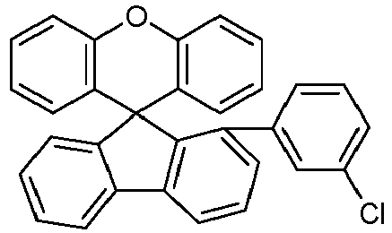


82% 2-5 


89% 2-6 


69% 2-7 


88% 2-8 


85% 2-9 


75% 2-10 


75% - Es werden OLED-Vorrichtungen gemäß der vorliegenden Anmeldung sowie Vergleichsvorrichtungen hergestellt, um die technischen Effekte der erfindungsgemäßen OLED-Devices zu zeigen. Die OLEDs werden gemäß dem allgemeinen Verfahren, das in den Ausführungsbeispielen der
Offenlegungsschrift WO 2004/058911 beschrieben ist, hergestellt, sofern unten nichts anderes angegeben ist. - Die hergestellten OLEDs haben als Substrate Glassplatten, welche mit strukturiertem ITO (Indium-Zinn-Oxid) in einer Dicke von 50 nm beschichtet sind. Die Schichten, welche auf das Substrat folgen, ihre Dicke und die Substanzen, aus denen sie bestehen, werden für jede Beispielvorrichtung in einer der folgenden Tabellen separat aufgelistet. Als Gegenelektrode wird als letzte Schicht eine Aluminiumschicht in einer Dicke von 100 nm aufgetragen.
- Alle Materialien werden durch thermische Gasphasenabscheidung in einer Vakuumkammer aufgetragen. In den Beispielen besteht die Emissionsschicht immer aus wenigstens einem Matrixmaterial und einer emittierenden Verbindung als Dotand. Letztere wird dem Matrixmaterial bzw. den Matrixmaterialien durch Co-Evaporation zugefügt. Ein Ausdruck SMB:SEB (5%) bedeutet dabei, dass das Material SMB in einem Anteil von 95 Vol.-% in der Schicht vorliegt, und das Material SEB in einem Anteil von 5 Vol.-% in der Schicht vorliegt. Nicht nur die Emissionsschicht, sondern auch andere Schichten können analog aus einer Mischung von zwei oder mehr Materialien bestehen.
- Die OLEDs werden nach Standardmethoden charakterisiert. Hierzu werden die Elektrolumineszenzspektren, die externe Quanteneffizienz (EQE, gemessen in %) als Funktion der Leuchtdichte, berechnet aus Strom/Spannung/Leuchdichte-Kennlinien (IUL-Kennlinien) unter Annahme Lambert'scher Emissionscharakteristik, und die Lebensdauer bestimmt. Der Ausdruck EQE @ 40 mA/cm2 bedeutet dann zum Beispiel die externe Quanteneffizienz bei einer Betriebsleuchtdichte von 40 mA/cm2. Die Lebensdauer wird für grün emittierende Vorrichtungen bei 20 mA/cm2, und für blau emittierende Vorrichtungen bei 60 mA/cm2 gemessen. Unter Annahme eines exponentiellen Abfalls bei den OLEDs werden die LT80-Werte für die Lebensdauer dann mit einem Beschleunigungsfaktor von 1.8 auf die Lebensdauer bei 1000 cd/m2 hin angenähert. LT80 @ 1000 cd/m2 ist dann die angenäherte Lebensdauer, bis zu der die OLED von einer initialen Leuchtdichte von 1000 cd/m2 auf eine Leuchtdichte von 800 cd/m2 abgefallen ist.
- Die chemischen Strukturen der Materialien, die in den Beispielen eingesetzt werden, ist in Tabelle A genannt. Die Synthese der Spiroxanthen-Amine erfolgt wie im vorangehenden Synthesebeispiel-Teil, oder sie kann wie im Stand der Technik bekannt, beispielsweise wie in
WO 2014/072017 offenbart, erfolgen.Tabelle A 


F4TCNQ LiQ H1 


H2 TEG ETM 


SMB SEB HTMV1 = HIM 


HTMV2 HTM1 HTM2 


HTM4 HTM5 HTM6 


HTM7 HTM8 HTM9 


HTM13 HTM14 HTM15 - Es werden die folgenden OLEDs V3 (Vergleichsbeispiel) und E3, E5, E7, E9, E10, E14, E15, und E16 (nicht Bestandteil der beanspruchten Erfindung) hergestellt.
- V3 als Vergleichsbeispiel enthält die Verbindung HIM (ein Spirobifluorenderivat) als HTL- und HIL-Material. Die oben genannten Verwendungsbeispiele E3, E5, E7, E9, E10, E14, E15, und E16 enthalten die Materialien HTM2, HTM4, HTM5, HTM6, HTM7, HTM8, HTM9, HTM13, HTM14, und HTM15 als HTL- und HIL-Materialien. Ansonsten ist ihr Aufbau identisch zu dem von V3 (Tabelle 1).
- Für Vorrichtungen E3, E5, E7, E9, E10, E14, E15 und E16 wird ein starker Anstieg in der Lebensdauer verglichen mit dem Beispiel V3 beobachtet (Tabelle 2).
- Dies zeigt die hervorragende Eignung der Spiroxanthen-Amine HTM2, HTM4, HTM6, HTM8, HTM9, HTM13 und HTM14 als HIL- und HTL-Materialien, verglichen mit dem HTL-/HIL-Material HIM gemäß dem Stand der Technik.
Tabelle 1: Aufbau der OLEDs Bsp HIL HTL EBL EML ETL EIL Dicke / nm Dicke / nm Dicke / nm Dicke / nm Dicke / nm Dicke / nm V3 HIM:F4TCNQ(5%) HIM HTMV2 SMB:SEB(5%) ETM:LiQ(50%) LiQ 20nm 180nm 10nm 20 nm 30 nm 1nm E3 HTM2:F4TCNQ(5%) HTM2 HTMV2 SMB:SEB(5%) ETM:LiQ(50%) LiQ 20nm 180nm 10nm 20 nm 30 nm 1nm E5 HTM4:F4TCNQ(5%) HTM4 HTMV2 SMB:SEB(5%) ETM:LiQ(50%) LiQ 20nm 180nm 10nm 20 nm 30 nm 1nm E7 HTM6:F4TCNQ(5%) HTM6 HTMV2 SMB:SEB(5%) ETM:LiQ(50°,6) LiQ 20nm 180nm 10nm 20 nm 30 nm 1nm E9 HTM8:F4TCNQ(5%) HTM8 HTMV2 SMB:SEB(5%) ETM:LiQ(50°,6) LiQ 20nm 180nm 10nm 20 nm 30 nm 1nm E10 HTM9:F4TCNQ(5%) HTM9 HTMV2 SMB:SEB(5%) ETM:LiQ(50°,6) LiQ 20nm 180nm 10nm 20 nm 30 nm 1nm E14 HTM5:F4TCNQ(5%) HTM13 HTMV2 SMB:SEB(5%) ETM:LiQ(50°,6) LiQ 20nm 180nm 10nm 20 nm 30 nm 1nm E15 HTM6:F4TCNQ(5%) HTM14 HTMV2 SMB:SEB(5%) ETM:LiQ(50°,6) LiQ 20nm 180nm 10nm 20 nm 30 nm 1nm E16 HTM7:F4TCNQ(5%) HTM15 HTMV2 SMB:SEB(5%) ETM:LiQ(50°,6) LiQ 20nm 180nm 10nm 20 nm 30 nm 1nm Tabelle 2: Daten der OLEDs Bsp. U @ 10mA/cm2 LT80 @ 1000cd/m2 [V] [h] V3 3.8 4790 E3 4.4 6800 E5 4.3 4960 E7 3.8 5610 E9 4.3 5180 E10 4.2 7390 E14 3.9 5500 E15 3.8 6600 E16 4.0 7400 - Ein Vergleich zwischen OLEDs, die sich lediglich durch die Tatsache, dass die Spiroxanthen-Amine in der EBL anstatt in der HTL / HIL enthalten sind, unterscheiden, ist in den folgenden Tabellen 3 und 4 gezeigt.
- Tabelle 3 zeigt dabei den Aufbau der Vergleichs-OLEDs.
- Tabelle 4 zeigt dabei die Ergebnisse der Direktvergleiche einander gegenübergestellt. In einer Zeile sind jeweils die miteinander zu vergleichenden Daten aufgelistet. In allen Fällen werden für den Fall, dass die Spiro-Xanthene in der HIL/HTL enthalten sind, signifikant höhere Lebensdauern erhalten (Beispiele auf der rechten Seite der Tabelle 4). Dies zeigt die Vorteile, die durch die Verwendung der Spiroxanthen-Aminverbindungen in der HIL und der HTL von OLEDs erhalten werden.
Tabelle 3: Aufbau der OLEDs Bsp HIL HTL EBL EML ETL EIL Dicke / nm Dicke / nm Dicke / nm Dicke / nm Dicke / nm Dicke / nm E17 HIM:F4TCNQ(5°,6) 20nm HIM 180nm HTM2 10nm SMB:SEB(5%) 20 nm ETM:LiQ(50%) 30 nm LiQ 1nm E19 HIM:F4TCNQ(5°,6) 20nm HIM 180nm HTM4 10nm SMB:SEB(5%) 20 nm ETM:LiQ(50%) 30 nm LiQ 1nm E21 HIM:F4TCNQ(5°,6) 20nm HIM 180nm HTM6 20nm SMB:SEB(5%) 20 nm ETM:LiQ(50%) 30 nm LiQ 1nm E23 HIM:F4TCNQ(5°,6) 20nm HIM 180nm HTM8 10nm SMB:SEB(5%) 20 nm ETM:LiQ(50%) 30 nm LiQ 1nm E24 HIM:F4TCNQ(5°,6) 20nm HIM 180nm HTM9 10nm SMB:SEB(5%) 20 nm ETM:LiQ(50%) 30 nm LiQ 1nm Tabelle 4: Daten der OLEDs Bsp. U @ 10mA/cm2 LT80 @ 1000cd/m2 LT80 @ 1000cd/m2 U @ 10mA/cm2 Bsp. [V] [h] [h] [V] E17 3.9 3082 6800 4.4 E3 E19 3.8 2278 4960 4.3 E5 E21 3.9 2464 5610 3.8 E7 E23 3.7 3881 5180 4.3 E9 E24 3.7 4126 7390 4.2 E10 - Die folgenden OLEDs V1, V2, E1 und E2 werden hergestellt (Aufbau s. Tabelle 5).
- V1 und V2 sind Vergleichsbeispiele, die ein 4-Spirobifluoren-Amin (HTMV2) als EBL-Material verwenden. V1 unterscheidet sich von V2 dadurch, dass ein anderes Spirobifluoren-Amin als HIL- und HTL-Material verwendet wird (HTMV1 in V1, und HTMV2 in V2).
- E1 ist ein Direktvergleich zu V1. In E1 wird das Spiroxanthen-Amin HTM1 als EBL-Material anstelle des Spirobifluoren-Amins HTMV2 verwendet. E2 ist ein Direktvergleich zu V2. In E2 wird das Spiroxanthen-Amin HTM1 als EBL-Material anstelle des Spirobifluoren-Amins HTMV2 verwendet.
- Sowohl für E1 als auch für E2 wird ein starker relativer Anstieg der Lebensdauer (LT80) beobachtet, verglichen mit den Beispielen V1 und V2. Parallel dazu verbessert sich die Effizienz der OLEDs (Tabelle 6).
- Dies zeigt den technischen Effekt, der mit 1-Spiroxanthen-Aminen HTM1 und HTM2 erzielt wird, insbesondere bei der Verwendung als EBL-Materialien.
Tabelle 5: Aufbau der OLEDs Bsp. HIL HTL EBL EML HBL ETL EIL Dicke / nm Dicke / nm Dicke / nm Dicke / nm Dicke / nm Dicke / nm Dicke / nm V1 HTMV1: F4TCNQ(5%) 20nm HTMV1 220nm HTMV2 10nm H1:H2(29%): TEG(12%) 30 nm ETM 10 nm ETM: LiQ(50°,6) 30 nm LiQ 1nm E1 HTMV1: F4TCNQ(5%) 20nm HTMV1 220nm HTM1 10nm H1:H2(29%): TEG(12%) 30 nm ETM 10 nm ETM: LiQ(50°,6) 30 nm LiQ 1nm V2 HTMV2: F4TCNQ(5%) 20nm HTMV2 220nm HTMV2 10nm H1:H2(29%): TEG(12%) 30 nm ETM 10 nm ETM: LiQ(50°,6) 30 nm LiQ 1nm E2 HTMV2: F4TCNQ(5%) 20nm HTMV2 220nm HTM1 10nm H1:H2(29%): TEG(12%) 30 nm ETM 10 nm ETM: LiQ(50°,6) 30 nm LiQ 1nm Tabelle 6: Daten der OLEDs Ex. U @ 2mA/cm2 EQE @ 2mA/cm2 LT80 @ 1000 cd/m2 [V] % [h] V1 3.1 17.4 53400 E1 3.3 18.0 69900 V2 3.2 17.7 69000 E2 3.5 17.9 76400
Claims (12)
- Verbindung einer Formel (I)
 A entspricht einer Formel (A)
 Ar1 ist Dibenzofuranyl, das mit einem oder mehreren Resten R1 substituiert sein kann;Y ist gewählt aus einer Einfachbindung, BR1, C(R1)2, C(R1)2-C(R1)2, Si(R1)2, Si(R1)2-Si(R1)2, C=O, C=NR1, C=C(R1)2, C(=O)N(R1), O, S, S=O, SO2 und NR1;k ist gleich 0;m ist gleich 0 oder 1; wobei die Gruppe A über die mit * markierte Bindung an den Rest der Verbindung der Formel (I) gebunden ist;E ist eine Einfachbindung;X ist O oder S;Z ist bei jedem Auftreten gleich oder verschieden CR2 oder N oder C, wobei eine Gruppe Z genau dann gleich C ist, wenn eine Gruppe A oder E an die betreffende Gruppe Z gebunden ist;R1 ist bei jedem Auftreten gleich oder verschieden gewählt aus H, D, F, C(=O)R3, CN, Si(R3)3, N(R3)2, P(=O)(R3)2, OR3, S(=O)R3, S(=O)2R3, geradkettigen Alkyl- oder Alkoxygruppen mit 1 bis 20 C-Atomen, verzweigten oder cyclischen Alkyl- oder Alkoxygruppen mit 3 bis 20 C-Atomen, Alkenyl- oder Alkinylgruppen mit 2 bis 20 C-Atomen, aromatischen Ringsystemen mit 6 bis 40 aromatischen Ringatomen, und heteroaromatischen Ringsystemen mit 5 bis 40 aromatischen Ringatomen; wobei zwei oder mehr Reste R1 miteinander verknüpft sein können und einen Ring bilden können; wobei die genannten Alkyl-, Alkoxy-, Alkenyl- und Alkinylgruppen und die genannten aromatischen Ringsysteme und heteroaromatischen Ringsysteme jeweils mit einem oder mehreren Resten R3 substituiert sein können; und wobei eine oder mehrere CH2-Gruppen in den genannten Alkyl-, Alkoxy-, Alkenyl- und Alkinylgruppen durch -R3C=CR3-, -C=C-, Si(R3)2, C=O, C=NR3, -C(=O)O-, -C(=O)NR3-, NR3, P(=O)(R3), -O-, -S-, SO oder SO2 ersetzt sein können;R2 ist bei jedem Auftreten gleich oder verschieden gewählt aus H, D, F, C(=O)R3, CN, Si(R3)3, N(R3)2, P(=O)(R3)2, OR3, S(=O)R3, S(=O)2R3, geradkettigen Alkyl- oder Alkoxygruppen mit 1 bis 20 C-Atomen, verzweigten oder cyclischen Alkyl- oder Alkoxygruppen mit 3 bis 20 C-Atomen, Alkenyl- oder Alkinylgruppen mit 2 bis 20 C-Atomen, aromatischen Ringsystemen mit 6 bis 40 aromatischen Ringatomen, und heteroaromatischen Ringsystemen mit 5 bis 40 aromatischen Ringatomen; wobei die genannten Alkyl-, Alkoxy-, Alkenyl-und Alkinylgruppen und die genannten aromatischen Ringsysteme und heteroaromatischen Ringsysteme jeweils mit einem oder mehreren Resten R3 substituiert sein können; und wobei eine oder mehrere CH2-Gruppen in den genannten Alkyl-, Alkoxy-, Alkenyl- und Alkinylgruppen durch -R3C=CR3-, -C=C-, Si(R3)2, C=O, C=NR3, -C(=O)O-, -C(=O)NR3-, NR3, P(=O)(R3), -O-, -S-, SO oder SO2 ersetzt sein können;R3 ist bei jedem Auftreten gleich oder verschieden gewählt aus H, D, F, C(=O)R4, CN, Si(R4)3, N(R4)2, P(=O)(R4)2, OR4, S(=O)R4, S(=O)2R4, geradkettigen Alkyl- oder Alkoxygruppen mit 1 bis 20 C-Atomen, verzweigten oder cyclischen Alkyl- oder Alkoxygruppen mit 3 bis 20 C-Atomen, Alkenyl- oder Alkinylgruppen mit 2 bis 20 C-Atomen, aromatischen Ringsystemen mit 6 bis 40 aromatischen Ringatomen, und heteroaromatischen Ringsystemen mit 5 bis 40 aromatischen Ringatomen; wobei zwei oder mehr Reste R3 miteinander verknüpft sein können und einen Ring bilden können; wobei die genannten Alkyl-, Alkoxy-, Alkenyl- und Alkinylgruppen und die genannten aromatischen Ringsysteme und heteroaromatischen Ringsysteme jeweils mit einem oder mehreren Resten R4 substituiert sein können; und wobei eine oder mehrere CH2-Gruppen in den genannten Alkyl-, Alkoxy-, Alkenyl- und Alkinylgruppen durch -R4C=CR4-, -C=C-, Si(R4)2, C=O, C=NR4, -C(=O)O-, -C(=O)NR4-, NR4, P(=O)(R4), -O-, -S-, SO oder SO2 ersetzt sein können;R4 ist bei jedem Auftreten gleich oder verschieden gewählt aus H, D, F, CN, Alkyl- oder Alkoxygruppen mit 1 bis 20 C-Atomen, Alkenyl- oder Alkinylgruppen mit 2 bis 20 C-Atomen, aromatischen Ringsystemen mit 6 bis 40 aromatischen Ringatomen und heteroaromatischen Ringsystemen mit 5 bis 40 aromatischen Ringatomen; wobei zwei oder mehr Reste R4 miteinander verknüpft sein können und einen Ring bilden können; und wobei die genannten Alkyl-, Alkoxy-, Alkenyl- und Alkinylgruppen, aromatischen Ringsysteme und heteroaromatischen Ringsysteme mit F oder CN substituiert sein können;i ist gleich 1;n ist bei jedem Auftreten gleich oder verschieden 0 oder 1, wobei die Summe aller indices n gleich 1, 2, 3 oder 4 ist.
 - Verbindung nach Anspruch 1, dadurch gekennzeichnet, dass X gleich O ist.
- Verbindung nach Anspruch 1 oder 2, dadurch gekennzeichnet, dass die Summe der indices n gleich 1 ist.
- Verbindung nach einem oder mehreren der Ansprüche 1 bis 3, dadurch gekennzeichnet, dass R1 bei jedem Auftreten gleich oder verschieden gewählt ist aus H, F, CN, geradkettigen Alkylgruppen mit 1 bis 20 C-Atomen, verzweigten oder cyclischen Alkylgruppen mit 3 bis 20 C-Atomen, aromatischen Ringsystemen mit 6 bis 40 aromatischen Ringatomen, und heteroaromatischen Ringsystemen mit 5 bis 40 aromatischen Ringatomen; wobei die genannten Alkylgruppen, die genannten aromatischen Ringsysteme und die genannten heteroaromatischen Ringsysteme jeweils mit einem oder mehreren Resten R3 substituiert sein können.
- Verbindung nach einem oder mehreren der Ansprüche 1 bis 4, dadurch gekennzeichnet, dass R2 bei jedem Auftreten gleich oder verschieden gewählt ist aus H, F, CN, geradkettigen Alkylgruppen mit 1 bis 20 C-Atomen, verzweigten oder cyclischen Alkylgruppen mit 3 bis 20 C-Atomen, aromatischen Ringsystemen mit 6 bis 40 aromatischen Ringatomen, und heteroaromatischen Ringsystemen mit 5 bis 40 aromatischen Ringatomen; wobei die genannten Alkylgruppen, die genannten aromatischen Ringsysteme und die genannten heteroaromatischen Ringsysteme jeweils mit einem oder mehreren Resten R3 substituiert sein können.
- Verbindung nach einem oder mehreren der Ansprüche 1 bis 5, dadurch gekennzeichnet, dass R3 bei jedem Auftreten gleich oder verschieden gewählt ist aus H, F, CN, geradkettigen Alkylgruppen mit 1 bis 20 C-Atomen, verzweigten oder cyclischen Alkylgruppen mit 3 bis 20 C-Atomen, aromatischen Ringsystemen mit 6 bis 40 aromatischen Ringatomen, und heteroaromatischen Ringsystemen mit 5 bis 40 aromatischen Ringatomen; wobei die genannten Alkylgruppen, die genannten aromatischen Ringsysteme und die genannten heteroaromatischen Ringsysteme jeweils mit einem oder mehreren Resten R4 substituiert sein können.
- Verbindung nach einem oder mehreren der Ansprüche 1 bis 6, dadurch gekennzeichnet, dass die Verbindung der Formel (I) einer der folgenden Formeln entspricht


- Verbindung nach Anspruch 7, dadurch gekennzeichnet, dass X gleich O ist, und sie an den unsubstituiert gezeichneten Positionen an den Benzolringen jeweils unsubstituiert ist.
- Verbindung nach einem oder mehreren der Ansprüche 1 bis 8, dadurch gekennzeichnet, dass m gleich 0 ist.
- Elektronische Vorrichtung, gewählt aus der Gruppe bestehend aus organischen integrierten Schaltungen (OICs), organischen Feld-Effekt-Transistoren (OFETs), organischen Dünnfilmtransistoren (OTFTs), organischen lichtemittierenden Transistoren (OLETs), organischen Solarzellen (OSCs), organischen optischen Detektoren, organischen Photorezeptoren, organischen Feld-Quench-Devices (OFQDs), organischen lichtemittierenden elektrochemischen Zellen (OLECs), organischen Laserdioden (O-Laser) und organischen Elektrolumineszenzvorrichtungen (OLEDs), dadurch gekennzeichnet, dass sie eine Verbindung nach einem oder mehreren der Ansprüche 1 bis 9 enthält.
- Elektronische Vorrichtung gemäß Anspruch 10, dadurch gekennzeichnet, dass sie eine organische Elektrolumineszenzvorrichtung (OLED) ist.
- Verwendung einer Verbindung gemäß einem oder mehreren der Ansprüche 1 bis 9 in einer elektronischen Vorrichtung, bevorzugt einer organischen Elektrolumineszenzvorrichtung (OLED).
Priority Applications (1)
| Application Number | Priority Date | Filing Date | Title |
|---|---|---|---|
| EP23186951.2A EP4255151A3 (de) | 2016-10-10 | 2017-10-06 | Spiro[fluoren-9,9'-(thio)xanthen] verbindungen |
Applications Claiming Priority (3)
| Application Number | Priority Date | Filing Date | Title |
|---|---|---|---|
| EP16193116 | 2016-10-10 | ||
| EP17787893.1A EP3523834B1 (de) | 2016-10-10 | 2017-10-06 | Elektronische vorrichtung |
| PCT/EP2017/075437 WO2018069167A1 (de) | 2016-10-10 | 2017-10-06 | Elektronische vorrichtung |
Related Parent Applications (2)
| Application Number | Title | Priority Date | Filing Date |
|---|---|---|---|
| EP17787893.1A Division-Into EP3523834B1 (de) | 2016-10-10 | 2017-10-06 | Elektronische vorrichtung |
| EP17787893.1A Division EP3523834B1 (de) | 2016-10-10 | 2017-10-06 | Elektronische vorrichtung |
Related Child Applications (1)
| Application Number | Title | Priority Date | Filing Date |
|---|---|---|---|
| EP23186951.2A Division EP4255151A3 (de) | 2016-10-10 | 2017-10-06 | Spiro[fluoren-9,9'-(thio)xanthen] verbindungen |
Publications (2)
| Publication Number | Publication Date |
|---|---|
| EP4113643A1 EP4113643A1 (de) | 2023-01-04 |
| EP4113643B1 true EP4113643B1 (de) | 2023-08-09 |
Family
ID=57137859
Family Applications (3)
| Application Number | Title | Priority Date | Filing Date |
|---|---|---|---|
| EP22190898.1A Active EP4113643B1 (de) | 2016-10-10 | 2017-10-06 | Spiro[fluoren-9,9'-(thio)xanthen] verbindungen |
| EP23186951.2A Pending EP4255151A3 (de) | 2016-10-10 | 2017-10-06 | Spiro[fluoren-9,9'-(thio)xanthen] verbindungen |
| EP17787893.1A Active EP3523834B1 (de) | 2016-10-10 | 2017-10-06 | Elektronische vorrichtung |
Family Applications After (2)
| Application Number | Title | Priority Date | Filing Date |
|---|---|---|---|
| EP23186951.2A Pending EP4255151A3 (de) | 2016-10-10 | 2017-10-06 | Spiro[fluoren-9,9'-(thio)xanthen] verbindungen |
| EP17787893.1A Active EP3523834B1 (de) | 2016-10-10 | 2017-10-06 | Elektronische vorrichtung |
Country Status (7)
| Country | Link |
|---|---|
| US (2) | US20200044160A1 (de) |
| EP (3) | EP4113643B1 (de) |
| JP (1) | JP6987870B2 (de) |
| KR (4) | KR102333243B1 (de) |
| CN (3) | CN111978283A (de) |
| TW (1) | TWI764942B (de) |
| WO (1) | WO2018069167A1 (de) |
Families Citing this family (26)
| Publication number | Priority date | Publication date | Assignee | Title |
|---|---|---|---|---|
| CN109867652B (zh) * | 2017-12-04 | 2023-11-10 | Cmdl有限公司 | 新型有机化合物及包含其的有机电致发光器件 |
| KR20190120538A (ko) * | 2018-04-16 | 2019-10-24 | 주식회사 두산 | 유기 발광 화합물 및 이를 이용한 유기 전계 발광 소자 |
| KR102290023B1 (ko) * | 2018-11-06 | 2021-08-13 | 주식회사 엘지화학 | 유기 발광 소자 |
| US20230059210A1 (en) * | 2018-11-29 | 2023-02-23 | Merck Patent Gmbh | Electronic device |
| KR102684985B1 (ko) * | 2018-12-07 | 2024-07-12 | 엘지디스플레이 주식회사 | 신규 화합물, 이를 포함하는 유기발광소자 및 유기발광 표시장치 |
| KR102100581B1 (ko) * | 2019-01-30 | 2020-04-14 | 두산솔루스 주식회사 | 유기 발광 화합물 및 이를 이용한 유기 전계 발광 소자 |
| KR102360902B1 (ko) * | 2019-02-08 | 2022-02-09 | 주식회사 엘지화학 | 신규한 헤테로 고리 화합물 및 이를 이용한 유기발광 소자 |
| WO2020218680A1 (ko) * | 2019-04-25 | 2020-10-29 | 두산솔루스 주식회사 | 유기 화합물 및 이를 이용한 유기 전계 발광 소자 |
| TW202110788A (zh) | 2019-05-03 | 2021-03-16 | 德商麥克專利有限公司 | 電子裝置 |
| TW202110789A (zh) | 2019-05-03 | 2021-03-16 | 德商麥克專利有限公司 | 電子裝置 |
| KR102780443B1 (ko) * | 2019-10-25 | 2025-03-11 | 주식회사 엘지화학 | 신규한 아민계 화합물 및 이를 이용한 유기발광 소자 |
| KR102780442B1 (ko) * | 2019-10-25 | 2025-03-11 | 주식회사 엘지화학 | 신규한 아민계 화합물 및 이를 이용한 유기발광 소자 |
| US12545667B2 (en) | 2019-11-19 | 2026-02-10 | Duk San Neolux Co., Ltd. | Compound for organic electronic element, organic electronic element using the same, and an electronic device thereof |
| CN118745171A (zh) * | 2019-11-19 | 2024-10-08 | 德山新勒克斯有限公司 | 用于有机电子元件的化合物、使用所述化合物的有机电子元件及其电子装置 |
| US11925112B2 (en) | 2019-11-19 | 2024-03-05 | Duk San Neolux Co., Ltd. | Compound for organic electronic element, organic electronic element using the same, and an electronic device thereof |
| CN111205262B (zh) * | 2020-01-21 | 2023-04-25 | 吉林省元合电子材料有限公司 | 一种含有螺芴基团的胺衍生物及其在有机电致发光器件中的应用 |
| KR102199111B1 (ko) * | 2020-02-17 | 2021-01-06 | 솔루스첨단소재 주식회사 | 유기 화합물 및 이를 이용한 유기 전계 발광 소자 |
| KR102768533B1 (ko) * | 2020-05-14 | 2025-02-18 | 덕산네오룩스 주식회사 | 유기전기소자용 화합물을 포함하는 유기전기소자 및 그 전자 장치 |
| TW202208594A (zh) | 2020-05-27 | 2022-03-01 | 德商麥克專利有限公司 | 電子裝置用材料 |
| KR102807691B1 (ko) * | 2020-07-31 | 2025-05-19 | 덕산네오룩스 주식회사 | 유기전기 소자용 화합물, 이를 이용한 유기전기소자 및 그 전자 장치 |
| CN112521361B (zh) * | 2020-12-18 | 2022-09-20 | 河南省科学院化学研究所有限公司 | 一种螺[芴-9,9’-氧杂蒽]类化合物及其制备方法 |
| TW202328052A (zh) * | 2021-09-08 | 2023-07-16 | 德商麥克專利有限公司 | 電子裝置 |
| CN114426530B (zh) * | 2022-02-10 | 2025-11-07 | 阜阳欣奕华新材料科技股份有限公司 | 一种螺芴杂蒽类化合物及其在发光层掺杂材料中的应用 |
| CN120051463A (zh) | 2022-09-29 | 2025-05-27 | 出光兴产株式会社 | 化合物、有机电致发光元件用材料、有机电致发光元件和电子设备 |
| CN118324733A (zh) * | 2024-06-17 | 2024-07-12 | 浙江华显光电科技有限公司 | 一种有机化合物、具有该化合物的oled和有机发光装置 |
| WO2025262148A1 (en) | 2024-06-21 | 2025-12-26 | Merck Patent Gmbh | Materials for organic light emitting devices |
Family Cites Families (160)
| Publication number | Priority date | Publication date | Assignee | Title |
|---|---|---|---|---|
| US5061569A (en) | 1990-07-26 | 1991-10-29 | Eastman Kodak Company | Electroluminescent device with organic electroluminescent medium |
| DE4111878A1 (de) | 1991-04-11 | 1992-10-15 | Wacker Chemie Gmbh | Leiterpolymere mit konjugierten doppelbindungen |
| JP3295088B2 (ja) | 1993-09-29 | 2002-06-24 | 出光興産株式会社 | 有機エレクトロルミネッセンス素子 |
| JPH07133483A (ja) | 1993-11-09 | 1995-05-23 | Shinko Electric Ind Co Ltd | El素子用有機発光材料及びel素子 |
| EP0676461B1 (de) | 1994-04-07 | 2002-08-14 | Covion Organic Semiconductors GmbH | Spiroverbindungen und ihre Verwendung als Elektrolumineszenzmaterialien |
| DE4436773A1 (de) | 1994-10-14 | 1996-04-18 | Hoechst Ag | Konjugierte Polymere mit Spirozentren und ihre Verwendung als Elektrolumineszenzmaterialien |
| JP3865406B2 (ja) | 1995-07-28 | 2007-01-10 | 住友化学株式会社 | 2,7−アリール−9−置換フルオレン及び9−置換フルオレンオリゴマー及びポリマー |
| DE19614971A1 (de) | 1996-04-17 | 1997-10-23 | Hoechst Ag | Polymere mit Spiroatomen und ihre Verwendung als Elektrolumineszenzmaterialien |
| JP3302945B2 (ja) | 1998-06-23 | 2002-07-15 | ネースディスプレイ・カンパニー・リミテッド | 新規な有機金属発光物質およびそれを含む有機電気発光素子 |
| DE19846766A1 (de) | 1998-10-10 | 2000-04-20 | Aventis Res & Tech Gmbh & Co | Konjugierte Polymere, enthaltend spezielle Fluorenbausteine mit verbesserten Eigenschaften |
| US6166172A (en) | 1999-02-10 | 2000-12-26 | Carnegie Mellon University | Method of forming poly-(3-substituted) thiophenes |
| EP1729327B2 (de) | 1999-05-13 | 2022-08-10 | The Trustees Of Princeton University | Verwendung einer phosphoreszierenden Iridiumverbindung als Emissionsmolekül in einer organischen lichtemittierenden Vorrichtung |
| EP1933395B2 (de) | 1999-12-01 | 2019-08-07 | The Trustees of Princeton University | Komplex der Formel L2IrX |
| KR100377321B1 (ko) | 1999-12-31 | 2003-03-26 | 주식회사 엘지화학 | 피-형 반도체 성질을 갖는 유기 화합물을 포함하는 전기소자 |
| US6660410B2 (en) | 2000-03-27 | 2003-12-09 | Idemitsu Kosan Co., Ltd. | Organic electroluminescence element |
| US20020121638A1 (en) | 2000-06-30 | 2002-09-05 | Vladimir Grushin | Electroluminescent iridium compounds with fluorinated phenylpyridines, phenylpyrimidines, and phenylquinolines and devices made with such compounds |
| EP1325671B1 (de) | 2000-08-11 | 2012-10-24 | The Trustees Of Princeton University | Organometallische verbdindungen und emissionsverschobene organische elektrolumineszens |
| JP4154140B2 (ja) | 2000-09-26 | 2008-09-24 | キヤノン株式会社 | 金属配位化合物 |
| JP4154138B2 (ja) | 2000-09-26 | 2008-09-24 | キヤノン株式会社 | 発光素子、表示装置及び金属配位化合物 |
| JP4154139B2 (ja) | 2000-09-26 | 2008-09-24 | キヤノン株式会社 | 発光素子 |
| EP2365735B1 (de) | 2000-11-24 | 2013-08-28 | Toray Industries Inc. | Luminiszentes Elementmaterial und lumineszentes Element damit |
| KR20080110928A (ko) | 2001-03-10 | 2008-12-19 | 메르크 파텐트 게엠베하 | 유기 반도체 용액 및 분산액 |
| DE10141624A1 (de) | 2001-08-24 | 2003-03-06 | Covion Organic Semiconductors | Lösungen polymerer Halbleiter |
| JP4843889B2 (ja) * | 2001-09-26 | 2011-12-21 | 東レ株式会社 | 発光素子 |
| KR100691543B1 (ko) | 2002-01-18 | 2007-03-09 | 주식회사 엘지화학 | 새로운 전자 수송용 물질 및 이를 이용한 유기 발광 소자 |
| ITRM20020411A1 (it) | 2002-08-01 | 2004-02-02 | Univ Roma La Sapienza | Derivati dello spirobifluorene, loro preparazione e loro uso. |
| US7839074B2 (en) | 2002-08-23 | 2010-11-23 | Idemitsu Kosan Co., Ltd. | Organic electroluminescence device and anthracene derivative |
| US20060035109A1 (en) | 2002-09-20 | 2006-02-16 | Idemitsu Kosan Co., Ltd. | Organic electroluminescent element |
| GB0226010D0 (en) | 2002-11-08 | 2002-12-18 | Cambridge Display Tech Ltd | Polymers for use in organic electroluminescent devices |
| US20060063027A1 (en) | 2002-12-23 | 2006-03-23 | Covion Organic Semiconductors Gmbh | Organic electroluminescent element |
| DE10304819A1 (de) | 2003-02-06 | 2004-08-19 | Covion Organic Semiconductors Gmbh | Carbazol-enthaltende konjugierte Polymere und Blends, deren Darstellung und Verwendung |
| DE10310887A1 (de) | 2003-03-11 | 2004-09-30 | Covion Organic Semiconductors Gmbh | Matallkomplexe |
| EP2174932B1 (de) | 2003-03-13 | 2019-07-03 | Idemitsu Kosan Co., Ltd. | Stickstoffhaltiges heterozyklisches Derivat und daraus erhältliches organisches Elektrolumineszenzelement |
| JP4411851B2 (ja) | 2003-03-19 | 2010-02-10 | コニカミノルタホールディングス株式会社 | 有機エレクトロルミネッセンス素子 |
| EP1618170A2 (de) | 2003-04-15 | 2006-01-25 | Covion Organic Semiconductors GmbH | Mischungen von organischen zur emission befähigten halbleitern und matrixmaterialien, deren verwendung und elektronikbauteile enthaltend diese mischungen |
| JP4635870B2 (ja) | 2003-04-23 | 2011-02-23 | コニカミノルタホールディングス株式会社 | 有機エレクトロルミネッセンス素子、照明装置及び表示装置 |
| US7014925B2 (en) | 2003-04-29 | 2006-03-21 | Canon Kabushiki Kaisha | Heterogeneous spiro compounds in organic light emitting device elements |
| EP1491568A1 (de) | 2003-06-23 | 2004-12-29 | Covion Organic Semiconductors GmbH | Halbleitende Polymere |
| DE10328627A1 (de) | 2003-06-26 | 2005-02-17 | Covion Organic Semiconductors Gmbh | Neue Materialien für die Elektrolumineszenz |
| DE10337346A1 (de) | 2003-08-12 | 2005-03-31 | Covion Organic Semiconductors Gmbh | Konjugierte Polymere enthaltend Dihydrophenanthren-Einheiten und deren Verwendung |
| DE10338550A1 (de) | 2003-08-19 | 2005-03-31 | Basf Ag | Übergangsmetallkomplexe mit Carbenliganden als Emitter für organische Licht-emittierende Dioden (OLEDs) |
| DE10345572A1 (de) | 2003-09-29 | 2005-05-19 | Covion Organic Semiconductors Gmbh | Metallkomplexe |
| US7795801B2 (en) | 2003-09-30 | 2010-09-14 | Konica Minolta Holdings, Inc. | Organic electroluminescent element, illuminator, display and compound |
| JP2007517079A (ja) | 2003-10-22 | 2007-06-28 | メルク パテント ゲーエムベーハー | エレクトロルミネセンスのための新規材料、およびそれらの使用 |
| DE102004008304A1 (de) | 2004-02-20 | 2005-09-08 | Covion Organic Semiconductors Gmbh | Organische elektronische Vorrichtungen |
| WO2005086538A1 (ja) | 2004-03-05 | 2005-09-15 | Idemitsu Kosan Co., Ltd. | 有機エレクトロルミネッセンス素子及び有機エレクトロルミネッセンス表示装置 |
| US7790890B2 (en) | 2004-03-31 | 2010-09-07 | Konica Minolta Holdings, Inc. | Organic electroluminescence element material, organic electroluminescence element, display device and illumination device |
| KR100787425B1 (ko) | 2004-11-29 | 2007-12-26 | 삼성에스디아이 주식회사 | 페닐카바졸계 화합물 및 이를 이용한 유기 전계 발광 소자 |
| DE102004020298A1 (de) | 2004-04-26 | 2005-11-10 | Covion Organic Semiconductors Gmbh | Elektrolumineszierende Polymere und deren Verwendung |
| DE102004023277A1 (de) | 2004-05-11 | 2005-12-01 | Covion Organic Semiconductors Gmbh | Neue Materialmischungen für die Elektrolumineszenz |
| US7598388B2 (en) | 2004-05-18 | 2009-10-06 | The University Of Southern California | Carbene containing metal complexes as OLEDs |
| CN1960957A (zh) | 2004-05-27 | 2007-05-09 | 出光兴产株式会社 | 不对称芘衍生物以及使用该衍生物的有机电致发光器件 |
| JP4862248B2 (ja) | 2004-06-04 | 2012-01-25 | コニカミノルタホールディングス株式会社 | 有機エレクトロルミネッセンス素子、照明装置及び表示装置 |
| DE102004032527A1 (de) | 2004-07-06 | 2006-02-02 | Covion Organic Semiconductors Gmbh | Elektrolumineszierende Polymere |
| ITRM20040352A1 (it) | 2004-07-15 | 2004-10-15 | Univ Roma La Sapienza | Derivati oligomerici dello spirobifluorene, loro preparazione e loro uso. |
| EP1655359A1 (de) | 2004-11-06 | 2006-05-10 | Covion Organic Semiconductors GmbH | Organische Elektrolumineszenzvorrichtung |
| EP1669386A1 (de) | 2004-12-06 | 2006-06-14 | Covion Organic Semiconductors GmbH | Teilkonjugierte Polymere, deren Darstellung und Verwendung |
| JP5242373B2 (ja) | 2005-03-16 | 2013-07-24 | メルク パテント ゲーエムベーハー | 有機エレクトロルミネセンスデバイスのための新規材料 |
| KR100949214B1 (ko) | 2005-03-18 | 2010-03-24 | 이데미쓰 고산 가부시키가이샤 | 방향족 아민 유도체 및 그것을 사용한 유기 전기발광 소자 |
| US8334058B2 (en) | 2005-04-14 | 2012-12-18 | Merck Patent Gmbh | Compounds for organic electronic devices |
| EP1888706B1 (de) | 2005-05-03 | 2017-03-01 | Merck Patent GmbH | Organische elektrolumineszenzvorrichtung und in deren herstellung verwendete boronsäure- und borinsäure-derivate |
| DE102005023437A1 (de) | 2005-05-20 | 2006-11-30 | Merck Patent Gmbh | Verbindungen für organische elektronische Vorrichtungen |
| DE102005026651A1 (de) | 2005-06-09 | 2006-12-14 | Merck Patent Gmbh | Neue Materialien für organische Elektrolumineszenzvorrichtungen |
| JP2007015961A (ja) | 2005-07-06 | 2007-01-25 | Idemitsu Kosan Co Ltd | ピレン誘導体及びそれらを用いた有機エレクトロルミネッセンス素子 |
| BRPI0613785A2 (pt) | 2005-07-08 | 2011-02-01 | Unilever Nv | produto alimentìcio que contém amido, processo para a preparação de células vegetais intactas contendo amido e processo para a preparação do produto alimentìcio que contém amido |
| DE102005037734B4 (de) | 2005-08-10 | 2018-02-08 | Merck Patent Gmbh | Elektrolumineszierende Polymere, ihre Verwendung und bifunktionelle monomere Verbindungen |
| WO2007063754A1 (ja) | 2005-12-01 | 2007-06-07 | Nippon Steel Chemical Co., Ltd. | 有機電界発光素子用化合物及び有機電界発光素子 |
| DE102005058557A1 (de) | 2005-12-08 | 2007-06-14 | Merck Patent Gmbh | Organische Elektrolumineszenzvorrichtung |
| US8795847B2 (en) | 2005-12-08 | 2014-08-05 | Merck Patent Gmbh | Materials for organic electroluminescent devices |
| DE102005060473A1 (de) | 2005-12-17 | 2007-06-28 | Merck Patent Gmbh | Konjugierte Polymere, deren Darstellung und Verwendung |
| JP4929186B2 (ja) | 2005-12-27 | 2012-05-09 | 出光興産株式会社 | 有機エレクトロルミネッセンス素子用材料及び有機エレクトロルミネッセンス素子 |
| DE102006013802A1 (de) | 2006-03-24 | 2007-09-27 | Merck Patent Gmbh | Neue Materialien für organische Elektrolumineszenzvorrichtungen |
| DE102006025777A1 (de) | 2006-05-31 | 2007-12-06 | Merck Patent Gmbh | Neue Materialien für organische Elektrolumineszenzvorrichtungen |
| DE102006025846A1 (de) | 2006-06-02 | 2007-12-06 | Merck Patent Gmbh | Neue Materialien für organische Elektrolumineszenzvorrichtungen |
| DE102006031990A1 (de) | 2006-07-11 | 2008-01-17 | Merck Patent Gmbh | Neue Materialien für organische Elektrolumineszenzvorrichtungen |
| US8062769B2 (en) | 2006-11-09 | 2011-11-22 | Nippon Steel Chemical Co., Ltd. | Indolocarbazole compound for use in organic electroluminescent device and organic electroluminescent device |
| DE102007002714A1 (de) | 2007-01-18 | 2008-07-31 | Merck Patent Gmbh | Neue Materialien für organische Elektrolumineszenzvorrichtungen |
| US8044390B2 (en) | 2007-05-25 | 2011-10-25 | Idemitsu Kosan Co., Ltd. | Material for organic electroluminescent device, organic electroluminescent device, and organic electroluminescent display |
| DE102007024850A1 (de) | 2007-05-29 | 2008-12-04 | Merck Patent Gmbh | Neue Materialien für organische Elektrolumineszenzvorrichtungen |
| DE102007031220B4 (de) | 2007-07-04 | 2022-04-28 | Novaled Gmbh | Chinoide Verbindungen und deren Verwendung in halbleitenden Matrixmaterialien, elektronischen und optoelektronischen Bauelementen |
| KR101414914B1 (ko) | 2007-07-18 | 2014-07-04 | 이데미쓰 고산 가부시키가이샤 | 유기 전계발광 소자용 재료 및 유기 전계발광 소자 |
| DE102007053771A1 (de) | 2007-11-12 | 2009-05-14 | Merck Patent Gmbh | Organische Elektrolumineszenzvorrichtungen |
| US7862908B2 (en) | 2007-11-26 | 2011-01-04 | National Tsing Hua University | Conjugated compounds containing hydroindoloacridine structural elements, and their use |
| ATE554073T1 (de) | 2007-11-30 | 2012-05-15 | Idemitsu Kosan Co | Azaindenofluorendionderivat, material für ein organisches elektrolumineszierendes gerät und organisches lumineszierendes gerät |
| DE102008008953B4 (de) | 2008-02-13 | 2019-05-09 | Merck Patent Gmbh | Neue Materialien für organische Elektrolumineszenzvorrichtungen |
| JP5416906B2 (ja) * | 2008-02-18 | 2014-02-12 | 凸版印刷株式会社 | 蛍光性化合物、発光性インク組成物および有機el素子 |
| TWI478624B (zh) | 2008-03-27 | 2015-03-21 | Nippon Steel & Sumikin Chem Co | Organic electroluminescent elements |
| US8057712B2 (en) | 2008-04-29 | 2011-11-15 | Novaled Ag | Radialene compounds and their use |
| DE102008033943A1 (de) | 2008-07-18 | 2010-01-21 | Merck Patent Gmbh | Neue Materialien für organische Elektrolumineszenzvorrichtungen |
| DE102008035413A1 (de) | 2008-07-29 | 2010-02-04 | Merck Patent Gmbh | Verbindungen für organische elektronische Vorrichtungen |
| DE102008036982A1 (de) | 2008-08-08 | 2010-02-11 | Merck Patent Gmbh | Organische Elektrolumineszenzvorrichtung |
| US8119037B2 (en) | 2008-10-16 | 2012-02-21 | Novaled Ag | Square planar transition metal complexes and organic semiconductive materials using them as well as electronic or optoelectric components |
| KR101506919B1 (ko) | 2008-10-31 | 2015-03-30 | 롬엔드하스전자재료코리아유한회사 | 신규한 유기 전자재료용 화합물 및 이를 포함하는 유기 전자 소자 |
| DE102008056688A1 (de) | 2008-11-11 | 2010-05-12 | Merck Patent Gmbh | Materialien für organische Elektrolumineszenzvorrichtungen |
| JP5701766B2 (ja) | 2008-11-11 | 2015-04-15 | メルク パテント ゲーエムベーハー | 有機エレクトロルミネセント素子 |
| DE102008064200A1 (de) | 2008-12-22 | 2010-07-01 | Merck Patent Gmbh | Organische Elektrolumineszenzvorrichtung |
| DE102009009277B4 (de) | 2009-02-17 | 2023-12-07 | Merck Patent Gmbh | Organische elektronische Vorrichtung, Verfahren zu deren Herstellung und Verwendung von Verbindungen |
| DE102009023155A1 (de) | 2009-05-29 | 2010-12-02 | Merck Patent Gmbh | Materialien für organische Elektrolumineszenzvorrichtungen |
| DE102009031021A1 (de) | 2009-06-30 | 2011-01-05 | Merck Patent Gmbh | Materialien für organische Elektrolumineszenzvorrichtungen |
| DE102009041289A1 (de) | 2009-09-16 | 2011-03-17 | Merck Patent Gmbh | Organische Elektrolumineszenzvorrichtung |
| DE102009048791A1 (de) | 2009-10-08 | 2011-04-14 | Merck Patent Gmbh | Materialien für organische Elektrolumineszenzvorrichtungen |
| DE102009053191A1 (de) * | 2009-11-06 | 2011-05-12 | Merck Patent Gmbh | Materialien für elektronische Vorrichtungen |
| ES2525757T3 (es) | 2009-12-14 | 2014-12-30 | Basf Se | Complejos metálicos que contienen ligandos de diazabencimidazolcarbeno y su uso en OLED |
| WO2011077691A1 (ja) | 2009-12-21 | 2011-06-30 | 出光興産株式会社 | ピレン誘導体を用いた有機エレクトロルミネッセンス素子 |
| DE102010005697A1 (de) | 2010-01-25 | 2011-07-28 | Merck Patent GmbH, 64293 | Verbindungen für elektronische Vorrichtungen |
| DE102010012738A1 (de) | 2010-03-25 | 2011-09-29 | Merck Patent Gmbh | Materialien für organische Elektrolumineszenzvorrichtungen |
| DE102010013495A1 (de) | 2010-03-31 | 2011-10-06 | Siemens Aktiengesellschaft | Dotierstoff für eine Lochleiterschicht für organische Halbleiterbauelemente und Verwendung dazu |
| DE102010019306B4 (de) | 2010-05-04 | 2021-05-20 | Merck Patent Gmbh | Organische Elektrolumineszenzvorrichtungen |
| DE102010045405A1 (de) | 2010-09-15 | 2012-03-15 | Merck Patent Gmbh | Materialien für organische Elektrolumineszenzvorrichtungen |
| DE102010048607A1 (de) | 2010-10-15 | 2012-04-19 | Merck Patent Gmbh | Verbindungen für elektronische Vorrichtungen |
| DE102010048608A1 (de) | 2010-10-15 | 2012-04-19 | Merck Patent Gmbh | Materialien für organische Elektrolumineszenzvorrichtungen |
| DE112011104715A5 (de) | 2011-01-13 | 2014-02-06 | Merck Patent Gmbh | Verbindungen für organische Elektrolumineszenzvorrichtungen |
| EP2699571B1 (de) | 2011-04-18 | 2018-09-05 | Merck Patent GmbH | Materialien für organische elektrolumineszenzvorrichtungen |
| KR101970940B1 (ko) | 2011-05-05 | 2019-04-22 | 메르크 파텐트 게엠베하 | 전자 소자용 화합물 |
| JP6174030B2 (ja) | 2011-09-21 | 2017-08-02 | メルク パテント ゲーエムベーハー | 有機エレクトロルミネッセンスデバイス用のカルバゾール誘導体 |
| US10305040B2 (en) | 2011-11-17 | 2019-05-28 | Merck Patent Gmbh | Spiro dihydroacridine derivatives and the use thereof as materials for organic electroluminescence devices |
| KR102015765B1 (ko) | 2012-02-14 | 2019-10-21 | 메르크 파텐트 게엠베하 | 유기 전계발광 소자용 스피로비플루오렌 화합물 |
| DE102012209523A1 (de) | 2012-06-06 | 2013-12-12 | Osram Opto Semiconductors Gmbh | Hauptgruppenmetallkomplexe als p-Dotanden für organische elektronische Matrixmaterialien |
| WO2013185871A1 (en) | 2012-06-12 | 2013-12-19 | Merck Patent Gmbh | Compounds for electronic devices |
| KR20130140303A (ko) * | 2012-06-14 | 2013-12-24 | (주) 에프엔지리서치 | 유기전계발광 소자 제조용 신규 화합물 |
| JP6422861B2 (ja) | 2012-06-29 | 2018-11-14 | メルク パテント ゲーエムベーハー | 2,7−ピレン構造単位を含むポリマー |
| KR101807925B1 (ko) | 2012-07-23 | 2017-12-11 | 메르크 파텐트 게엠베하 | 화합물 및 유기 전계 발광 디바이스 |
| EP3424907B1 (de) | 2012-07-23 | 2025-03-12 | Merck Patent GmbH | Verbindungen und organische elektronische vorrichtungen |
| CN104488359B (zh) | 2012-07-23 | 2018-01-23 | 默克专利有限公司 | 2‑二芳基氨基芴的衍生物和含有所述2‑二芳基氨基芴衍生物的有机电子复合体 |
| CN104684886B (zh) | 2012-09-04 | 2017-07-18 | 默克专利有限公司 | 用于电子器件的化合物 |
| KR102153871B1 (ko) * | 2012-10-09 | 2020-09-09 | 메르크 파텐트 게엠베하 | 전자 디바이스 |
| KR101716069B1 (ko) * | 2012-11-12 | 2017-03-13 | 메르크 파텐트 게엠베하 | 전자 소자용 재료 |
| CN104884572B (zh) | 2013-01-03 | 2017-09-19 | 默克专利有限公司 | 用于电子器件的材料 |
| KR102249277B1 (ko) | 2013-05-15 | 2021-05-07 | 에스에프씨 주식회사 | 유기발광 화합물 및 이를 포함하는 유기전계발광소자 |
| US10651389B2 (en) | 2013-07-02 | 2020-05-12 | Merck Patent Gmbh | Materials for electronic devices |
| JP6567520B2 (ja) | 2013-08-15 | 2019-08-28 | メルク パテント ゲーエムベーハー | 電子素子のための材料 |
| WO2014111269A2 (de) | 2013-10-14 | 2014-07-24 | Merck Patent Gmbh | Materialien für elektronische vorrichtungen |
| CN103664860A (zh) | 2013-12-03 | 2014-03-26 | 方圆环球光电技术盐城有限公司 | 一种新颖的有机电致发光化合物及制备 |
| CN103666454A (zh) * | 2013-12-03 | 2014-03-26 | 方圆环球光电技术盐城有限公司 | 一种新颖的有机电致发光化合物及制备 |
| CN103666455A (zh) | 2013-12-03 | 2014-03-26 | 方圆环球光电技术盐城有限公司 | 一种新颖螺芴氧杂蒽类有机发光材料及其制备 |
| JP6896422B2 (ja) | 2013-12-06 | 2021-06-30 | メルク パテント ゲーエムベーハー | 化合物および有機電子素子 |
| WO2015086108A1 (de) | 2013-12-12 | 2015-06-18 | Merck Patent Gmbh | Materialien für elektronische vorrichtungen |
| JP6591433B2 (ja) | 2014-03-07 | 2019-10-16 | メルク パテント ゲーエムベーハー | 電子素子のための材料 |
| KR102216673B1 (ko) * | 2014-03-11 | 2021-02-18 | 삼성디스플레이 주식회사 | 화합물 및 이를 포함한 유기 발광 소자 |
| JP6651460B2 (ja) | 2014-04-14 | 2020-02-19 | メルク パテント ゲーエムベーハー | 電子素子のための材料 |
| US11063221B2 (en) | 2014-04-16 | 2021-07-13 | Merck Patent Gmbh | Materials for electronic devices |
| KR102278853B1 (ko) * | 2014-06-17 | 2021-07-19 | 에스에프씨주식회사 | 방향족 아민기를 포함하는 신규한 아민 화합물 및 이를 포함하는 유기 발광 소자 |
| US9691989B2 (en) * | 2014-08-11 | 2017-06-27 | The University Of Hong Kong | Carbo- and heterocyclic spiro compounds as donor materials for organic photovoltaics and their preparation |
| US10396297B2 (en) * | 2014-10-24 | 2019-08-27 | Merck Patent Gmbh | Materials for electronic devices |
| US10510960B2 (en) | 2014-11-18 | 2019-12-17 | Merck Patent Gmbh | Materials for organic electroluminescent devices |
| US10573818B2 (en) | 2014-12-01 | 2020-02-25 | Merck Patent Gmbh | Materials for organic electroluminescent devices |
| US10224492B2 (en) | 2014-12-22 | 2019-03-05 | Merck Patent Gmbh | Materials for electronic devices |
| WO2016131521A1 (de) | 2015-02-16 | 2016-08-25 | Merck Patent Gmbh | Materialien auf basis von spirobifluorenderivaten für elektronische vorrichtungen |
| EP3274419B1 (de) | 2015-03-25 | 2019-04-03 | Merck Patent GmbH | Materialien für organische elektrolumineszenzvorrichtungen |
| KR101722861B1 (ko) * | 2015-07-28 | 2017-04-03 | 서울대학교산학협력단 | 마이크로알엔에이 193a를 포함하는 신경세포 분화 촉진용 조성물 및 방법 |
| JP6749999B2 (ja) | 2015-08-12 | 2020-09-02 | メルク、パテント、ゲゼルシャフト、ミット、ベシュレンクテル、ハフツングMerck Patent GmbH | 電子素子のための材料 |
| CN107922402B (zh) | 2015-08-14 | 2021-12-31 | 默克专利有限公司 | 用于有机电致发光器件的吩噁嗪衍生物 |
| KR102599157B1 (ko) | 2015-08-14 | 2023-11-06 | 메르크 파텐트 게엠베하 | 유기 전계발광 소자용 페녹사진 유도체 |
| JP6935391B2 (ja) | 2015-08-28 | 2021-09-15 | メルク、パテント、ゲゼルシャフト、ミット、ベシュレンクテル、ハフツングMerck Patent GmbH | 6,9,15,18−テトラヒドロ−s−インダセノ[1,2−b:5,6−b’]ジフルオレン誘導体、および電子素子におけるそれらの使用 |
| WO2017036573A1 (en) | 2015-08-28 | 2017-03-09 | Merck Patent Gmbh | Compounds for electronic devices |
| KR101781739B1 (ko) | 2015-10-07 | 2017-09-25 | 주식회사 엘지화학 | 신규 화합물 및 이를 포함하는 유기 발광 소자 |
| KR101755986B1 (ko) * | 2016-02-23 | 2017-07-07 | 주식회사 엘지화학 | 헤테로고리 화합물 및 이를 포함하는 유기 발광 소자 |
| CN105778891B (zh) * | 2016-03-11 | 2019-03-19 | 中节能万润股份有限公司 | 有机光电材料、其制备方法以及包括该有机材料的有机电致发光器件 |
| CN105924395B (zh) * | 2016-05-10 | 2018-11-30 | 中节能万润股份有限公司 | 一种蓝光掺杂材料、其制备方法及有机电致发光器件 |
| CN105906640B (zh) * | 2016-05-12 | 2018-03-30 | 中节能万润股份有限公司 | 一种蓝光掺杂材料的制备方法 |
-
2017
- 2017-10-05 TW TW106134335A patent/TWI764942B/zh not_active IP Right Cessation
- 2017-10-06 EP EP22190898.1A patent/EP4113643B1/de active Active
- 2017-10-06 JP JP2019540690A patent/JP6987870B2/ja active Active
- 2017-10-06 US US16/339,594 patent/US20200044160A1/en active Pending
- 2017-10-06 CN CN202010756399.1A patent/CN111978283A/zh active Pending
- 2017-10-06 WO PCT/EP2017/075437 patent/WO2018069167A1/de not_active Ceased
- 2017-10-06 KR KR1020197013271A patent/KR102333243B1/ko active Active
- 2017-10-06 KR KR1020227025302A patent/KR102711569B1/ko active Active
- 2017-10-06 EP EP23186951.2A patent/EP4255151A3/de active Pending
- 2017-10-06 EP EP17787893.1A patent/EP3523834B1/de active Active
- 2017-10-06 CN CN202310594455.XA patent/CN116751181A/zh active Pending
- 2017-10-06 CN CN201780058591.XA patent/CN109791979B/zh active Active
- 2017-10-06 KR KR1020217028098A patent/KR102425601B1/ko active Active
- 2017-10-06 KR KR1020247031824A patent/KR20240148440A/ko not_active Ceased
-
2023
- 2023-07-03 US US18/217,636 patent/US12604660B2/en active Active
Also Published As
| Publication number | Publication date |
|---|---|
| TWI764942B (zh) | 2022-05-21 |
| TW201827562A (zh) | 2018-08-01 |
| KR102425601B1 (ko) | 2022-07-27 |
| CN109791979B (zh) | 2023-06-20 |
| KR20190058640A (ko) | 2019-05-29 |
| EP3523834B1 (de) | 2023-01-25 |
| CN111978283A (zh) | 2020-11-24 |
| JP2019531608A (ja) | 2019-10-31 |
| EP4255151A2 (de) | 2023-10-04 |
| EP4255151A3 (de) | 2023-11-15 |
| EP4113643A1 (de) | 2023-01-04 |
| US20200044160A1 (en) | 2020-02-06 |
| JP6987870B2 (ja) | 2022-01-05 |
| KR102333243B1 (ko) | 2021-12-01 |
| KR102711569B1 (ko) | 2024-09-27 |
| KR20220107323A (ko) | 2022-08-02 |
| CN116751181A (zh) | 2023-09-15 |
| CN109791979A (zh) | 2019-05-21 |
| US12604660B2 (en) | 2026-04-14 |
| US20240008359A1 (en) | 2024-01-04 |
| WO2018069167A1 (de) | 2018-04-19 |
| EP3523834A1 (de) | 2019-08-14 |
| KR20240148440A (ko) | 2024-10-11 |
| KR20210112409A (ko) | 2021-09-14 |
Similar Documents
| Publication | Publication Date | Title |
|---|---|---|
| EP4113643B1 (de) | Spiro[fluoren-9,9'-(thio)xanthen] verbindungen | |
| EP3378857B1 (de) | Materialien für elektronische vorrichtungen | |
| EP3259330B1 (de) | Materialien auf basis von spirobifluorenderivaten für elektronische vorrichtungen | |
| EP3114102B1 (de) | Materialien für elektronische vorrichtungen | |
| EP3238286B1 (de) | Materialien für elektronische vorrichtungen | |
| EP3131901B1 (de) | Materialien für elektronische vorrichtungen | |
| EP2875092B1 (de) | Verbindungen und organische elektrolumineszierende vorrichtungen | |
| EP3033405B1 (de) | Materialien für elektronische vorrichtungen | |
| EP3411455B1 (de) | Materialien für elektronische vorrichtungen | |
| EP2931698B1 (de) | Materialien für elektronische vorrichtungen | |
| EP3615542B1 (de) | Verbindungen für elektronische vorrichtungen | |
| WO2014079527A1 (de) | Materialien für elektronische vorrichtungen | |
| EP4242286B1 (de) | Materialien für elektronische vorrichtungen | |
| EP3679023B1 (de) | Materialien für elektronische vorrichtungen | |
| EP4483687A2 (de) | Materialien für elektronische vorrichtungen | |
| EP3589624A1 (de) | Materialien für organische elektronische vorrichtungen | |
| EP4240718A1 (de) | Materialien für elektronische vorrichtungen | |
| EP4158703B1 (de) | Materialien für elektronische vorrichtungen | |
| EP4263512A1 (de) | Materialien für elektronische vorrichtungen | |
| EP4225733A2 (de) | Verbindungen für elektronische vorrichtungen | |
| EP3394036B1 (de) | Materialien für elektronische vorrichtungen | |
| WO2024126322A1 (de) | Materialien für elektronische vorrichtungen |
Legal Events
| Date | Code | Title | Description |
|---|---|---|---|
| PUAI | Public reference made under article 153(3) epc to a published international application that has entered the european phase |
Free format text: ORIGINAL CODE: 0009012 |
|
| STAA | Information on the status of an ep patent application or granted ep patent |
Free format text: STATUS: REQUEST FOR EXAMINATION WAS MADE |
|
| 17P | Request for examination filed |
Effective date: 20221128 |
|
| AC | Divisional application: reference to earlier application |
Ref document number: 3523834 Country of ref document: EP Kind code of ref document: P |
|
| AK | Designated contracting states |
Kind code of ref document: A1 Designated state(s): AL AT BE BG CH CY CZ DE DK EE ES FI FR GB GR HR HU IE IS IT LI LT LU LV MC MK MT NL NO PL PT RO RS SE SI SK SM TR |
|
| RBV | Designated contracting states (corrected) |
Designated state(s): AL AT BE BG CH CY CZ DE DK EE ES FI FR GB GR HR HU IE IS IT LI LT LU LV MC MK MT NL NO PL PT RO RS SE SI SK SM TR |
|
| REG | Reference to a national code |
Ref country code: DE Ref legal event code: R079 Ref document number: 502017015211 Country of ref document: DE Free format text: PREVIOUS MAIN CLASS: H01L0051540000 Ipc: H10K0085600000 Ref country code: DE Ref legal event code: R079 Free format text: PREVIOUS MAIN CLASS: H01L0051540000 Ipc: H10K0085600000 |
|
| GRAP | Despatch of communication of intention to grant a patent |
Free format text: ORIGINAL CODE: EPIDOSNIGR1 |
|
| STAA | Information on the status of an ep patent application or granted ep patent |
Free format text: STATUS: GRANT OF PATENT IS INTENDED |
|
| RIC1 | Information provided on ipc code assigned before grant |
Ipc: H10K 50/18 20230101ALN20230329BHEP Ipc: H10K 85/60 20230101AFI20230329BHEP |
|
| GRAJ | Information related to disapproval of communication of intention to grant by the applicant or resumption of examination proceedings by the epo deleted |
Free format text: ORIGINAL CODE: EPIDOSDIGR1 |
|
| STAA | Information on the status of an ep patent application or granted ep patent |
Free format text: STATUS: REQUEST FOR EXAMINATION WAS MADE |
|
| RIC1 | Information provided on ipc code assigned before grant |
Ipc: H10K 50/18 20230101ALN20230412BHEP Ipc: H10K 85/60 20230101AFI20230412BHEP |
|
| INTG | Intention to grant announced |
Effective date: 20230502 |
|
| RIN1 | Information on inventor provided before grant (corrected) |
Inventor name: EBERLE, THOMAS Inventor name: MONTENEGRO, ELVIRA Inventor name: MUJICA-FERNAUD, ELVIRA Inventor name: VOGES, FRANK |
|
| INTC | Intention to grant announced (deleted) | ||
| GRAP | Despatch of communication of intention to grant a patent |
Free format text: ORIGINAL CODE: EPIDOSNIGR1 |
|
| STAA | Information on the status of an ep patent application or granted ep patent |
Free format text: STATUS: GRANT OF PATENT IS INTENDED |
|
| P01 | Opt-out of the competence of the unified patent court (upc) registered |
Effective date: 20230519 |
|
| GRAS | Grant fee paid |
Free format text: ORIGINAL CODE: EPIDOSNIGR3 |
|
| GRAA | (expected) grant |
Free format text: ORIGINAL CODE: 0009210 |
|
| STAA | Information on the status of an ep patent application or granted ep patent |
Free format text: STATUS: THE PATENT HAS BEEN GRANTED |
|
| RIC1 | Information provided on ipc code assigned before grant |
Ipc: H10K 50/18 20230101ALN20230602BHEP Ipc: H10K 85/60 20230101AFI20230602BHEP |
|
| INTG | Intention to grant announced |
Effective date: 20230627 |
|
| AC | Divisional application: reference to earlier application |
Ref document number: 3523834 Country of ref document: EP Kind code of ref document: P |
|
| AK | Designated contracting states |
Kind code of ref document: B1 Designated state(s): AL AT BE BG CH CY CZ DE DK EE ES FI FR GB GR HR HU IE IS IT LI LT LU LV MC MK MT NL NO PL PT RO RS SE SI SK SM TR |
|
| REG | Reference to a national code |
Ref country code: GB Ref legal event code: FG4D Free format text: NOT ENGLISH |
|
| REG | Reference to a national code |
Ref country code: CH Ref legal event code: EP |
|
| REG | Reference to a national code |
Ref country code: DE Ref legal event code: R096 Ref document number: 502017015211 Country of ref document: DE |
|
| REG | Reference to a national code |
Ref country code: IE Ref legal event code: FG4D Free format text: LANGUAGE OF EP DOCUMENT: GERMAN |
|
| REG | Reference to a national code |
Ref country code: LT Ref legal event code: MG9D |
|
| REG | Reference to a national code |
Ref country code: NL Ref legal event code: MP Effective date: 20230809 |
|
| PG25 | Lapsed in a contracting state [announced via postgrant information from national office to epo] |
Ref country code: GR Free format text: LAPSE BECAUSE OF FAILURE TO SUBMIT A TRANSLATION OF THE DESCRIPTION OR TO PAY THE FEE WITHIN THE PRESCRIBED TIME-LIMIT Effective date: 20231110 |
|
| PG25 | Lapsed in a contracting state [announced via postgrant information from national office to epo] |
Ref country code: IS Free format text: LAPSE BECAUSE OF FAILURE TO SUBMIT A TRANSLATION OF THE DESCRIPTION OR TO PAY THE FEE WITHIN THE PRESCRIBED TIME-LIMIT Effective date: 20231209 |
|
| PG25 | Lapsed in a contracting state [announced via postgrant information from national office to epo] |
Ref country code: SE Free format text: LAPSE BECAUSE OF FAILURE TO SUBMIT A TRANSLATION OF THE DESCRIPTION OR TO PAY THE FEE WITHIN THE PRESCRIBED TIME-LIMIT Effective date: 20230809 Ref country code: RS Free format text: LAPSE BECAUSE OF FAILURE TO SUBMIT A TRANSLATION OF THE DESCRIPTION OR TO PAY THE FEE WITHIN THE PRESCRIBED TIME-LIMIT Effective date: 20230809 Ref country code: PT Free format text: LAPSE BECAUSE OF FAILURE TO SUBMIT A TRANSLATION OF THE DESCRIPTION OR TO PAY THE FEE WITHIN THE PRESCRIBED TIME-LIMIT Effective date: 20231211 Ref country code: NO Free format text: LAPSE BECAUSE OF FAILURE TO SUBMIT A TRANSLATION OF THE DESCRIPTION OR TO PAY THE FEE WITHIN THE PRESCRIBED TIME-LIMIT Effective date: 20231109 Ref country code: NL Free format text: LAPSE BECAUSE OF FAILURE TO SUBMIT A TRANSLATION OF THE DESCRIPTION OR TO PAY THE FEE WITHIN THE PRESCRIBED TIME-LIMIT Effective date: 20230809 Ref country code: LV Free format text: LAPSE BECAUSE OF FAILURE TO SUBMIT A TRANSLATION OF THE DESCRIPTION OR TO PAY THE FEE WITHIN THE PRESCRIBED TIME-LIMIT Effective date: 20230809 Ref country code: LT Free format text: LAPSE BECAUSE OF FAILURE TO SUBMIT A TRANSLATION OF THE DESCRIPTION OR TO PAY THE FEE WITHIN THE PRESCRIBED TIME-LIMIT Effective date: 20230809 Ref country code: IS Free format text: LAPSE BECAUSE OF FAILURE TO SUBMIT A TRANSLATION OF THE DESCRIPTION OR TO PAY THE FEE WITHIN THE PRESCRIBED TIME-LIMIT Effective date: 20231209 Ref country code: HR Free format text: LAPSE BECAUSE OF FAILURE TO SUBMIT A TRANSLATION OF THE DESCRIPTION OR TO PAY THE FEE WITHIN THE PRESCRIBED TIME-LIMIT Effective date: 20230809 Ref country code: GR Free format text: LAPSE BECAUSE OF FAILURE TO SUBMIT A TRANSLATION OF THE DESCRIPTION OR TO PAY THE FEE WITHIN THE PRESCRIBED TIME-LIMIT Effective date: 20231110 Ref country code: FI Free format text: LAPSE BECAUSE OF FAILURE TO SUBMIT A TRANSLATION OF THE DESCRIPTION OR TO PAY THE FEE WITHIN THE PRESCRIBED TIME-LIMIT Effective date: 20230809 |
|
| PG25 | Lapsed in a contracting state [announced via postgrant information from national office to epo] |
Ref country code: PL Free format text: LAPSE BECAUSE OF FAILURE TO SUBMIT A TRANSLATION OF THE DESCRIPTION OR TO PAY THE FEE WITHIN THE PRESCRIBED TIME-LIMIT Effective date: 20230809 |
|
| PG25 | Lapsed in a contracting state [announced via postgrant information from national office to epo] |
Ref country code: ES Free format text: LAPSE BECAUSE OF FAILURE TO SUBMIT A TRANSLATION OF THE DESCRIPTION OR TO PAY THE FEE WITHIN THE PRESCRIBED TIME-LIMIT Effective date: 20230809 |
|
| PG25 | Lapsed in a contracting state [announced via postgrant information from national office to epo] |
Ref country code: SM Free format text: LAPSE BECAUSE OF FAILURE TO SUBMIT A TRANSLATION OF THE DESCRIPTION OR TO PAY THE FEE WITHIN THE PRESCRIBED TIME-LIMIT Effective date: 20230809 Ref country code: RO Free format text: LAPSE BECAUSE OF FAILURE TO SUBMIT A TRANSLATION OF THE DESCRIPTION OR TO PAY THE FEE WITHIN THE PRESCRIBED TIME-LIMIT Effective date: 20230809 Ref country code: ES Free format text: LAPSE BECAUSE OF FAILURE TO SUBMIT A TRANSLATION OF THE DESCRIPTION OR TO PAY THE FEE WITHIN THE PRESCRIBED TIME-LIMIT Effective date: 20230809 Ref country code: EE Free format text: LAPSE BECAUSE OF FAILURE TO SUBMIT A TRANSLATION OF THE DESCRIPTION OR TO PAY THE FEE WITHIN THE PRESCRIBED TIME-LIMIT Effective date: 20230809 Ref country code: DK Free format text: LAPSE BECAUSE OF FAILURE TO SUBMIT A TRANSLATION OF THE DESCRIPTION OR TO PAY THE FEE WITHIN THE PRESCRIBED TIME-LIMIT Effective date: 20230809 Ref country code: CZ Free format text: LAPSE BECAUSE OF FAILURE TO SUBMIT A TRANSLATION OF THE DESCRIPTION OR TO PAY THE FEE WITHIN THE PRESCRIBED TIME-LIMIT Effective date: 20230809 Ref country code: SK Free format text: LAPSE BECAUSE OF FAILURE TO SUBMIT A TRANSLATION OF THE DESCRIPTION OR TO PAY THE FEE WITHIN THE PRESCRIBED TIME-LIMIT Effective date: 20230809 |
|
| REG | Reference to a national code |
Ref country code: DE Ref legal event code: R097 Ref document number: 502017015211 Country of ref document: DE |
|
| PG25 | Lapsed in a contracting state [announced via postgrant information from national office to epo] |
Ref country code: IT Free format text: LAPSE BECAUSE OF FAILURE TO SUBMIT A TRANSLATION OF THE DESCRIPTION OR TO PAY THE FEE WITHIN THE PRESCRIBED TIME-LIMIT Effective date: 20230809 Ref country code: MC Free format text: LAPSE BECAUSE OF FAILURE TO SUBMIT A TRANSLATION OF THE DESCRIPTION OR TO PAY THE FEE WITHIN THE PRESCRIBED TIME-LIMIT Effective date: 20230809 |
|
| REG | Reference to a national code |
Ref country code: CH Ref legal event code: PL |
|
| PLBE | No opposition filed within time limit |
Free format text: ORIGINAL CODE: 0009261 |
|
| STAA | Information on the status of an ep patent application or granted ep patent |
Free format text: STATUS: NO OPPOSITION FILED WITHIN TIME LIMIT |
|
| REG | Reference to a national code |
Ref country code: BE Ref legal event code: MM Effective date: 20231031 |
|
| PG25 | Lapsed in a contracting state [announced via postgrant information from national office to epo] |
Ref country code: LU Free format text: LAPSE BECAUSE OF NON-PAYMENT OF DUE FEES Effective date: 20231006 |
|
| PG25 | Lapsed in a contracting state [announced via postgrant information from national office to epo] |
Ref country code: LU Free format text: LAPSE BECAUSE OF NON-PAYMENT OF DUE FEES Effective date: 20231006 |
|
| 26N | No opposition filed |
Effective date: 20240513 |
|
| PG25 | Lapsed in a contracting state [announced via postgrant information from national office to epo] |
Ref country code: CH Free format text: LAPSE BECAUSE OF NON-PAYMENT OF DUE FEES Effective date: 20231031 |
|
| PG25 | Lapsed in a contracting state [announced via postgrant information from national office to epo] |
Ref country code: FR Free format text: LAPSE BECAUSE OF NON-PAYMENT OF DUE FEES Effective date: 20231009 Ref country code: CH Free format text: LAPSE BECAUSE OF NON-PAYMENT OF DUE FEES Effective date: 20231031 Ref country code: SI Free format text: LAPSE BECAUSE OF FAILURE TO SUBMIT A TRANSLATION OF THE DESCRIPTION OR TO PAY THE FEE WITHIN THE PRESCRIBED TIME-LIMIT Effective date: 20230809 |
|
| PG25 | Lapsed in a contracting state [announced via postgrant information from national office to epo] |
Ref country code: BE Free format text: LAPSE BECAUSE OF NON-PAYMENT OF DUE FEES Effective date: 20231031 |
|
| PG25 | Lapsed in a contracting state [announced via postgrant information from national office to epo] |
Ref country code: IE Free format text: LAPSE BECAUSE OF NON-PAYMENT OF DUE FEES Effective date: 20231006 |
|
| PG25 | Lapsed in a contracting state [announced via postgrant information from national office to epo] |
Ref country code: IE Free format text: LAPSE BECAUSE OF NON-PAYMENT OF DUE FEES Effective date: 20231006 |
|
| PG25 | Lapsed in a contracting state [announced via postgrant information from national office to epo] |
Ref country code: BG Free format text: LAPSE BECAUSE OF FAILURE TO SUBMIT A TRANSLATION OF THE DESCRIPTION OR TO PAY THE FEE WITHIN THE PRESCRIBED TIME-LIMIT Effective date: 20230809 |
|
| PG25 | Lapsed in a contracting state [announced via postgrant information from national office to epo] |
Ref country code: BG Free format text: LAPSE BECAUSE OF FAILURE TO SUBMIT A TRANSLATION OF THE DESCRIPTION OR TO PAY THE FEE WITHIN THE PRESCRIBED TIME-LIMIT Effective date: 20230809 |
|
| REG | Reference to a national code |
Ref country code: AT Ref legal event code: MM01 Ref document number: 1599046 Country of ref document: AT Kind code of ref document: T Effective date: 20231006 |
|
| PG25 | Lapsed in a contracting state [announced via postgrant information from national office to epo] |
Ref country code: AT Free format text: LAPSE BECAUSE OF NON-PAYMENT OF DUE FEES Effective date: 20231006 |
|
| PG25 | Lapsed in a contracting state [announced via postgrant information from national office to epo] |
Ref country code: AT Free format text: LAPSE BECAUSE OF NON-PAYMENT OF DUE FEES Effective date: 20231006 |
|
| PG25 | Lapsed in a contracting state [announced via postgrant information from national office to epo] |
Ref country code: CY Free format text: LAPSE BECAUSE OF FAILURE TO SUBMIT A TRANSLATION OF THE DESCRIPTION OR TO PAY THE FEE WITHIN THE PRESCRIBED TIME-LIMIT; INVALID AB INITIO Effective date: 20171006 |
|
| PG25 | Lapsed in a contracting state [announced via postgrant information from national office to epo] |
Ref country code: HU Free format text: LAPSE BECAUSE OF FAILURE TO SUBMIT A TRANSLATION OF THE DESCRIPTION OR TO PAY THE FEE WITHIN THE PRESCRIBED TIME-LIMIT; INVALID AB INITIO Effective date: 20171006 |
|
| PGFP | Annual fee paid to national office [announced via postgrant information from national office to epo] |
Ref country code: GB Payment date: 20250923 Year of fee payment: 9 |
|
| PG25 | Lapsed in a contracting state [announced via postgrant information from national office to epo] |
Ref country code: TR Free format text: LAPSE BECAUSE OF FAILURE TO SUBMIT A TRANSLATION OF THE DESCRIPTION OR TO PAY THE FEE WITHIN THE PRESCRIBED TIME-LIMIT Effective date: 20230809 |
|
| PGFP | Annual fee paid to national office [announced via postgrant information from national office to epo] |
Ref country code: DE Payment date: 20250923 Year of fee payment: 9 |