WO2011037005A1 - Plaque originale d'impression lithographique - Google Patents
Plaque originale d'impression lithographique Download PDFInfo
- Publication number
- WO2011037005A1 WO2011037005A1 PCT/JP2010/065285 JP2010065285W WO2011037005A1 WO 2011037005 A1 WO2011037005 A1 WO 2011037005A1 JP 2010065285 W JP2010065285 W JP 2010065285W WO 2011037005 A1 WO2011037005 A1 WO 2011037005A1
- Authority
- WO
- WIPO (PCT)
- Prior art keywords
- lithographic printing
- printing plate
- aluminum alloy
- plate precursor
- treatment
- Prior art date
- Legal status (The legal status is an assumption and is not a legal conclusion. Google has not performed a legal analysis and makes no representation as to the accuracy of the status listed.)
- Ceased
Links
Images



Classifications
-
- G—PHYSICS
- G03—PHOTOGRAPHY; CINEMATOGRAPHY; ANALOGOUS TECHNIQUES USING WAVES OTHER THAN OPTICAL WAVES; ELECTROGRAPHY; HOLOGRAPHY
- G03F—PHOTOMECHANICAL PRODUCTION OF TEXTURED OR PATTERNED SURFACES, e.g. FOR PRINTING, FOR PROCESSING OF SEMICONDUCTOR DEVICES; MATERIALS THEREFOR; ORIGINALS THEREFOR; APPARATUS SPECIALLY ADAPTED THEREFOR
- G03F7/00—Photomechanical, e.g. photolithographic, production of textured or patterned surfaces, e.g. printing surfaces; Materials therefor, e.g. comprising photoresists; Apparatus specially adapted therefor
- G03F7/004—Photosensitive materials
- G03F7/09—Photosensitive materials characterised by structural details, e.g. supports, auxiliary layers
-
- B—PERFORMING OPERATIONS; TRANSPORTING
- B41—PRINTING; LINING MACHINES; TYPEWRITERS; STAMPS
- B41C—PROCESSES FOR THE MANUFACTURE OR REPRODUCTION OF PRINTING SURFACES
- B41C1/00—Forme preparation
- B41C1/10—Forme preparation for lithographic printing; Master sheets for transferring a lithographic image to the forme
-
- B—PERFORMING OPERATIONS; TRANSPORTING
- B41—PRINTING; LINING MACHINES; TYPEWRITERS; STAMPS
- B41C—PROCESSES FOR THE MANUFACTURE OR REPRODUCTION OF PRINTING SURFACES
- B41C1/00—Forme preparation
- B41C1/10—Forme preparation for lithographic printing; Master sheets for transferring a lithographic image to the forme
- B41C1/1008—Forme preparation for lithographic printing; Master sheets for transferring a lithographic image to the forme by removal or destruction of lithographic material on the lithographic support, e.g. by laser or spark ablation; by the use of materials rendered soluble or insoluble by heat exposure, e.g. by heat produced from a light to heat transforming system; by on-the-press exposure or on-the-press development, e.g. by the fountain of photolithographic materials
-
- B—PERFORMING OPERATIONS; TRANSPORTING
- B41—PRINTING; LINING MACHINES; TYPEWRITERS; STAMPS
- B41C—PROCESSES FOR THE MANUFACTURE OR REPRODUCTION OF PRINTING SURFACES
- B41C1/00—Forme preparation
- B41C1/10—Forme preparation for lithographic printing; Master sheets for transferring a lithographic image to the forme
- B41C1/1008—Forme preparation for lithographic printing; Master sheets for transferring a lithographic image to the forme by removal or destruction of lithographic material on the lithographic support, e.g. by laser or spark ablation; by the use of materials rendered soluble or insoluble by heat exposure, e.g. by heat produced from a light to heat transforming system; by on-the-press exposure or on-the-press development, e.g. by the fountain of photolithographic materials
- B41C1/1016—Forme preparation for lithographic printing; Master sheets for transferring a lithographic image to the forme by removal or destruction of lithographic material on the lithographic support, e.g. by laser or spark ablation; by the use of materials rendered soluble or insoluble by heat exposure, e.g. by heat produced from a light to heat transforming system; by on-the-press exposure or on-the-press development, e.g. by the fountain of photolithographic materials characterised by structural details, e.g. protective layers, backcoat layers or several imaging layers
-
- B—PERFORMING OPERATIONS; TRANSPORTING
- B41—PRINTING; LINING MACHINES; TYPEWRITERS; STAMPS
- B41N—PRINTING PLATES OR FOILS; MATERIALS FOR SURFACES USED IN PRINTING MACHINES FOR PRINTING, INKING, DAMPING, OR THE LIKE; PREPARING SUCH SURFACES FOR USE AND CONSERVING THEM
- B41N1/00—Printing plates or foils; Materials therefor
- B41N1/04—Printing plates or foils; Materials therefor metallic
- B41N1/08—Printing plates or foils; Materials therefor metallic for lithographic printing
- B41N1/083—Printing plates or foils; Materials therefor metallic for lithographic printing made of aluminium or aluminium alloys or having such surface layers
-
- G—PHYSICS
- G03—PHOTOGRAPHY; CINEMATOGRAPHY; ANALOGOUS TECHNIQUES USING WAVES OTHER THAN OPTICAL WAVES; ELECTROGRAPHY; HOLOGRAPHY
- G03F—PHOTOMECHANICAL PRODUCTION OF TEXTURED OR PATTERNED SURFACES, e.g. FOR PRINTING, FOR PROCESSING OF SEMICONDUCTOR DEVICES; MATERIALS THEREFOR; ORIGINALS THEREFOR; APPARATUS SPECIALLY ADAPTED THEREFOR
- G03F7/00—Photomechanical, e.g. photolithographic, production of textured or patterned surfaces, e.g. printing surfaces; Materials therefor, e.g. comprising photoresists; Apparatus specially adapted therefor
- G03F7/20—Exposure; Apparatus therefor
-
- G—PHYSICS
- G03—PHOTOGRAPHY; CINEMATOGRAPHY; ANALOGOUS TECHNIQUES USING WAVES OTHER THAN OPTICAL WAVES; ELECTROGRAPHY; HOLOGRAPHY
- G03F—PHOTOMECHANICAL PRODUCTION OF TEXTURED OR PATTERNED SURFACES, e.g. FOR PRINTING, FOR PROCESSING OF SEMICONDUCTOR DEVICES; MATERIALS THEREFOR; ORIGINALS THEREFOR; APPARATUS SPECIALLY ADAPTED THEREFOR
- G03F7/00—Photomechanical, e.g. photolithographic, production of textured or patterned surfaces, e.g. printing surfaces; Materials therefor, e.g. comprising photoresists; Apparatus specially adapted therefor
- G03F7/26—Processing photosensitive materials; Apparatus therefor
- G03F7/30—Imagewise removal using liquid means
- G03F7/32—Liquid compositions therefor, e.g. developers
-
- B—PERFORMING OPERATIONS; TRANSPORTING
- B41—PRINTING; LINING MACHINES; TYPEWRITERS; STAMPS
- B41C—PROCESSES FOR THE MANUFACTURE OR REPRODUCTION OF PRINTING SURFACES
- B41C2201/00—Location, type or constituents of the non-imaging layers in lithographic printing formes
- B41C2201/02—Cover layers; Protective layers
-
- B—PERFORMING OPERATIONS; TRANSPORTING
- B41—PRINTING; LINING MACHINES; TYPEWRITERS; STAMPS
- B41C—PROCESSES FOR THE MANUFACTURE OR REPRODUCTION OF PRINTING SURFACES
- B41C2201/00—Location, type or constituents of the non-imaging layers in lithographic printing formes
- B41C2201/04—Intermediate layers
-
- B—PERFORMING OPERATIONS; TRANSPORTING
- B41—PRINTING; LINING MACHINES; TYPEWRITERS; STAMPS
- B41C—PROCESSES FOR THE MANUFACTURE OR REPRODUCTION OF PRINTING SURFACES
- B41C2201/00—Location, type or constituents of the non-imaging layers in lithographic printing formes
- B41C2201/10—Location, type or constituents of the non-imaging layers in lithographic printing formes characterised by inorganic compounds, e.g. pigments
-
- B—PERFORMING OPERATIONS; TRANSPORTING
- B41—PRINTING; LINING MACHINES; TYPEWRITERS; STAMPS
- B41C—PROCESSES FOR THE MANUFACTURE OR REPRODUCTION OF PRINTING SURFACES
- B41C2201/00—Location, type or constituents of the non-imaging layers in lithographic printing formes
- B41C2201/14—Location, type or constituents of the non-imaging layers in lithographic printing formes characterised by macromolecular organic compounds, e.g. binder, adhesives
-
- B—PERFORMING OPERATIONS; TRANSPORTING
- B41—PRINTING; LINING MACHINES; TYPEWRITERS; STAMPS
- B41C—PROCESSES FOR THE MANUFACTURE OR REPRODUCTION OF PRINTING SURFACES
- B41C2210/00—Preparation or type or constituents of the imaging layers, in relation to lithographic printing forme preparation
- B41C2210/02—Positive working, i.e. the exposed (imaged) areas are removed
-
- B—PERFORMING OPERATIONS; TRANSPORTING
- B41—PRINTING; LINING MACHINES; TYPEWRITERS; STAMPS
- B41C—PROCESSES FOR THE MANUFACTURE OR REPRODUCTION OF PRINTING SURFACES
- B41C2210/00—Preparation or type or constituents of the imaging layers, in relation to lithographic printing forme preparation
- B41C2210/04—Negative working, i.e. the non-exposed (non-imaged) areas are removed
-
- B—PERFORMING OPERATIONS; TRANSPORTING
- B41—PRINTING; LINING MACHINES; TYPEWRITERS; STAMPS
- B41C—PROCESSES FOR THE MANUFACTURE OR REPRODUCTION OF PRINTING SURFACES
- B41C2210/00—Preparation or type or constituents of the imaging layers, in relation to lithographic printing forme preparation
- B41C2210/06—Developable by an alkaline solution
-
- B—PERFORMING OPERATIONS; TRANSPORTING
- B41—PRINTING; LINING MACHINES; TYPEWRITERS; STAMPS
- B41C—PROCESSES FOR THE MANUFACTURE OR REPRODUCTION OF PRINTING SURFACES
- B41C2210/00—Preparation or type or constituents of the imaging layers, in relation to lithographic printing forme preparation
- B41C2210/14—Multiple imaging layers
-
- B—PERFORMING OPERATIONS; TRANSPORTING
- B41—PRINTING; LINING MACHINES; TYPEWRITERS; STAMPS
- B41C—PROCESSES FOR THE MANUFACTURE OR REPRODUCTION OF PRINTING SURFACES
- B41C2210/00—Preparation or type or constituents of the imaging layers, in relation to lithographic printing forme preparation
- B41C2210/22—Preparation or type or constituents of the imaging layers, in relation to lithographic printing forme preparation characterised by organic non-macromolecular additives, e.g. dyes, UV-absorbers, plasticisers
-
- B—PERFORMING OPERATIONS; TRANSPORTING
- B41—PRINTING; LINING MACHINES; TYPEWRITERS; STAMPS
- B41C—PROCESSES FOR THE MANUFACTURE OR REPRODUCTION OF PRINTING SURFACES
- B41C2210/00—Preparation or type or constituents of the imaging layers, in relation to lithographic printing forme preparation
- B41C2210/24—Preparation or type or constituents of the imaging layers, in relation to lithographic printing forme preparation characterised by a macromolecular compound or binder obtained by reactions involving carbon-to-carbon unsaturated bonds, e.g. acrylics, vinyl polymers
-
- B—PERFORMING OPERATIONS; TRANSPORTING
- B41—PRINTING; LINING MACHINES; TYPEWRITERS; STAMPS
- B41C—PROCESSES FOR THE MANUFACTURE OR REPRODUCTION OF PRINTING SURFACES
- B41C2210/00—Preparation or type or constituents of the imaging layers, in relation to lithographic printing forme preparation
- B41C2210/26—Preparation or type or constituents of the imaging layers, in relation to lithographic printing forme preparation characterised by a macromolecular compound or binder obtained by reactions not involving carbon-to-carbon unsaturated bonds
- B41C2210/262—Phenolic condensation polymers, e.g. novolacs, resols
Definitions
- the present invention relates to a lithographic printing plate precursor.
- an offset printing plate or a lithographic printing plate the surface of an aluminum alloy base plate is subjected to a surface treatment such as roughening treatment or anodizing treatment to form a support, and a photosensitive material is applied onto the support and dried.
- a so-called PS plate is used which has been subjected to plate making processing such as image exposure, development and gumming on the PS plate.
- the photosensitive layer that remains undissolved by the development process forms an image portion, while the portion where the photosensitive layer is removed and the underlying aluminum surface is hydrophilic has a hydrophilic property. Thus, a non-image part is formed.
- an aluminum alloy rolled plate that is lightweight and excellent in surface treatment, workability, and corrosion resistance is used.
- an aluminum alloy rolled sheet for such purposes conventionally, an aluminum alloy rolled sheet having a thickness of about 0.1 to 0.5 mm made of JIS1050, JIS1100, JIS3003, or the like has been used. Is used for a printing plate after roughening the surface and then anodizing it.
- Patent Document 1 an aluminum lithographic printing plate subjected to mechanical surface roughening treatment, chemical etching treatment, and anodized film treatment in order, or as described in Patent Document 2
- An aluminum lithographic printing plate subjected to electrochemical treatment, post-treatment and anodizing treatment in order, an aluminum lithographic printing plate subjected to chemical etching treatment and anodizing treatment described in Patent Document 3 are known. .
- Patent Document 4 storage is achieved by using an aluminum alloy support for a printing plate in which the number of aluminum carbides having a maximum length of 1 ⁇ m or more in a rolled plate made of a pure aluminum alloy is regulated to 30000 pieces / g or less. It is described that defects in the photosensitive layer can be suppressed.
- Patent Document 5 a lithographic printing plate precursor excellent in adhesion to a photosensitive layer and printing durability is obtained by using a support in which an intermetallic compound having a diameter of 0.1 ⁇ m or more is present at 5000 to 35000 / mm 2. It is described that it is obtained.
- Patent Document 6 discloses a laser using a support obtained by roughening an aluminum plate in which the density of intermetallic compounds existing at a depth of 2 ⁇ m or less from the surface is in the range of 500 to 35,000 / mm 2. A lithographic printing plate precursor excellent in exposure suitability and printing performance is described.
- Patent Document 7 a lithographic printing plate precursor is obtained using a support having a uniform rough surface state using an aluminum alloy in which intermetallic compounds are dispersed at a density of 3000 to 30000 pieces / mm 2 in the surface direction. It is described. However, even when these supports are used, it has not been sufficient to prevent the photosensitive layer from being defective when the lithographic printing plate precursor obtained is stored.
- the plate making process in the conventional PS plate requires an operation of dissolving and removing the non-image area with a highly alkaline developing solution after exposure, and simplifies such additional wet processing or Making it unnecessary is one problem that has been desired to be improved with respect to the prior art.
- disposal of the waste liquid discharged with wet processing has become a major concern for the entire industry due to consideration of the global environment, and the demand for improvement in this aspect has become even stronger.
- lithographic printing plate precursors that can be mounted on a printing machine and printed without being developed after exposure have been studied, and various methods have been proposed. Yes.
- One method of eliminating the processing step is to mount the exposed lithographic printing plate precursor on the plate cylinder of the printing press, and supply dampening water and ink while rotating the plate cylinder to remove the lithographic printing plate precursor.
- a lithographic printing plate precursor suitable for on-press development has an image recording layer that is soluble in fountain solution or an ink solvent, and is bright when developed on a press in a bright room. It is required to have room handling properties.
- Patent Document 8 describes a lithographic printing plate precursor in which an image recording layer in which fine particles of a thermoplastic hydrophobic polymer are dispersed in a hydrophilic binder polymer is provided on a hydrophilic support.
- a lithographic printing plate precursor is subjected to laser exposure, and the thermoplastic hydrophobic polymer particles in the image recording layer are coalesced by heat to form an image, and then the plate is mounted on a plate cylinder of a printing press, It is described that an unexposed portion can be removed (on-press development) with fountain solution and / or ink.
- This lithographic printing plate precursor also has suitability for handling a bright room because the photosensitive region is an infrared region.
- Patent Document 9 discloses a lithographic printing plate having an image recording layer containing at least one of thermoplastic polymer fine particles, polymer fine particles having a thermoreactive group, and microcapsules encapsulating a compound having a thermoreactive group. It is described that the original plate has good on-press developability, high sensitivity and high printing resistance.
- the lithographic printing plate precursors described in Patent Documents 8 and 9 have spots that appear where ink tends to adhere to a part of the surface of the non-image area when stored for a long period of time and appear on printed paper or the like. Or annular dirt (hereinafter also referred to as “micro-corrosive dirt”) may occur.
- lithographic printing plate precursors one promising method suitable for simple development processing is to use a hydrophilic layer in which hydrophobic thermoplastic polymer particles are dispersed in a hydrophilic binder polymer as an image recording layer.
- This is a lithographic printing plate precursor.
- the hydrophobic thermoplastic polymer particles are fused, and the hydrophilic layer surface is converted into an oleophilic image portion.
- Patent Documents 10 and 11 describe a method for producing a lithographic printing plate in which an image recording layer having hydrophobic thermoplastic polymer particles is developed by a simple development method.
- a positive recording material for infrared lasers having a photosensitive wavelength of 760 nm or more a lithographic printing plate material having an essential component of an alkaline aqueous solution-soluble binder resin and an infrared absorbing dye that absorbs light and generates heat is used.
- a positive recording material compatible with an infrared laser the solubility of the binder resin is substantially reduced in the non-exposed area (image area) due to the interaction between the infrared absorbing dye and the binder resin.
- the infrared absorbing dye or the like absorbs light and generates heat, the interaction between the infrared absorbing dye and the binder resin is weakened. As a result, at the time of development, only the exposed portion is dissolved and removed in the alkaline developer, and a lithographic printing plate is formed.
- the first problem of the present invention is that the roughened surface of the support has a uniform shape, and the lithographic printing plate using the support has excellent printing durability and stain resistance. There is no planographic printing plate precursor.
- a second object of the present invention is to provide a lithographic printing plate precursor excellent in printing durability, stain resistance and microcorrosion stain resistance.
- the third object of the present invention is to provide a lithographic printing plate precursor capable of suppressing the generation of pot-like residual film and development residue and obtaining a lithographic printing plate excellent in stain resistance.
- the exposed portion is cured and the ink Becomes an image part to which the toner is attached, and the unexposed part is developed to become a non-image part.
- a lithographic printing plate precursor is stored for a long period of time, there may be a problem that an exposed portion that should be an image portion is lost in a circle and becomes a non-image portion (in this application, it may be referred to as a “white spot failure”). is there).
- the present inventor has an aluminum alloy plate in which the density of intermetallic compounds on the surface is not less than a predetermined number, and the number of aluminum carbides having a predetermined size or more in the aluminum bulk is not more than the predetermined number. The present inventors have found that this problem can be solved by using a support prepared from the above, and have reached the first aspect of the present invention.
- the first aspect of the present invention provides the following (1) to (7).
- (1) Lithographic printing having a photosensitive layer and a protective layer in this order (A) a sensitizing dye, (B) a polymerization initiator, (C) a polymerizable compound, and (D) a binder polymer on a support.
- the above-mentioned support is an aluminum alloy in which the density of an intermetallic compound having an equivalent circle diameter of 0.2 ⁇ m or more on the surface is 35,000 pieces / mm 2 or more and the number of aluminum carbides having a maximum length of 1 ⁇ m or more is 30,000 pieces / g or less.
- the lithographic printing plate precursor as described in (1), wherein the support is a support obtained by subjecting the surface of the aluminum alloy plate to a roughening treatment including an electrochemical roughening treatment.
- the lithographic printing plate precursor as described in (1) or (2), wherein the support is further anodized after the roughening treatment and has an anodized film having an average thickness of 1.0 ⁇ m or more.
- lithographic printing plate precursor as described in any one of (1) to (4), wherein a photosensitive layer having a mass ratio of the polymerizable compound to the binder polymer and a polymerizable compound mass / binder polymer mass of 2 to 4 is provided.
- the sensitizing dye is a sensitizing dye having an absorption maximum at 350 to 450 nm.
- the protective layer is a composition containing polyvinyl alcohol.
- the image recording layer having hydrophobic thermoplastic polymer particles is an image recording layer in which hydrophobic thermoplastic polymer particles are arranged.
- the image recording layer easily contained moisture.
- anion the hydrophilic component anionized by the moisture
- the intermetallic compounds of the aluminum alloy plate are included in the aluminum alloy plate for a lithographic printing plate, for example, in JP-A No. 2005-330588, JP-A No. 2005-232596, and JP-A No. 11-151870. Contents related to intermetallic compounds are described. Specifically, the Al—Fe-based intermetallic compound is more likely to be a starting point of pits during electrolytic surface roughening than the Al—Fe—Si-based intermetallic compound, and among the Al—Fe-based intermetallic compounds, It is described that a metastable phase Al—Fe intermetallic compound tends to be the starting point of pits.
- JP-A-2005-330588 discloses that the number of metastable phase particles having a Fe / Al ratio of 0.6 or less is 0.35 or more with respect to the total number of intermetallic compound particles, and uniform sand. It is described that eyes form. Further, Japanese Patent Application Laid-Open No. 2005-232596 describes an aluminum alloy plate containing 0.5 to 2.0% of an average AlFe-based crystal precipitate. Japanese Patent Laid-Open No. 11-151870 is characterized in that the ratio of the number of Al—Fe intermetallic particles / the number of Al—Fe—Si intermetallic particles is 0.7 or more. However, these patent documents do not describe an intermetallic compound for suppressing corrosion of the aluminum substrate by the image recording layer.
- the present inventor is excellent in printing durability, stain resistance and micro-corrosion stain resistance by using a support made of an aluminum alloy plate having an intermetallic compound density of 35000 pieces / mm 2 or more on the surface. It was found that a lithographic printing plate precursor could be obtained, and the second and third aspects of the present invention were completed.
- the second aspect of the present invention provides the following (8) to (15).
- a lithographic printing plate precursor having an image recording layer containing (E) an infrared absorbing dye and (F) hydrophobic thermoplastic particles on a support
- a lithographic printing plate precursor, wherein the support is prepared using an aluminum alloy plate having a density of an intermetallic compound having a circle-equivalent diameter of 0.2 ⁇ m or more on the surface of 35000 pieces / mm 2 or more.
- the anodized film is formed by anodization using an electrolytic solution containing sulfuric acid or phosphoric acid. Lithographic printing plate precursor.
- the third aspect of the present invention provides the following (16) to (26).
- a lithographic printing plate precursor where the layer is removed with printing ink and / or fountain solution
- a lithographic printing plate precursor, wherein the support is prepared using an aluminum alloy plate having a density of an intermetallic compound having a circle-equivalent diameter of 0.2 ⁇ m or more on the surface of 35000 pieces / mm 2 or more.
- the peak count value of the Al—Fe-based intermetallic compound of the aluminum alloy plate measured using an X-ray diffractometer (XRD) is 400 cps or less, (16) to (16) above 21) The lithographic printing plate precursor as described in any one of 21).
- the peak count value of the AlFeSi-based intermetallic compound of the aluminum alloy plate measured using an X-ray diffractometer (XRD) is 30 cps or less, (16) to (22) A lithographic printing plate precursor as described in any of the above.
- An anodized film having micropores is formed on the surface of the support on the side where the image recording layer is formed, and the average pore diameter in the surface layer of the anodized film is 10 to 75 nm.
- the lithographic printing plate precursor as described in any one of (16) to (23) above, wherein the average value of the maximum diameter inside the pore is 1.1 to 3.0 times the average pore diameter.
- Lithographic printing plate precursor The lithographic printing plate precursor as described in any one of (16) to (25) above, wherein the aluminum alloy plate is an aluminum alloy plate produced by a continuous casting method.
- the present inventors have conducted extensive studies and as a result, by using the aluminum alloy plate having more than a circle equivalent diameter of more than intermetallic compound 0.2 [mu] m 35000 pieces / mm 2 on the surface forming It was found that by using such a support, it is possible to obtain a lithographic printing plate excellent in stain resistance by suppressing generation of pot-like residual film and development residue, and the fourth aspect of the present invention was completed.
- the fourth aspect of the present invention provides the following (27) to (36).
- (27) A lithographic printing plate precursor having an image recording layer containing (K) an infrared absorber and (L) an alkali-soluble resin on the support and having increased alkali-solubility in the exposed portion after infrared exposure.
- It said support is a lithographic printing plate precursor circle corresponding to the surface diameter is formed using an aluminum alloy plate having more than the above intermetallic compound 0.2 [mu] m 35000 pieces / mm 2.
- the aluminum alloy plate is obtained by continuous casting in which a molten aluminum alloy is supplied between a pair of cooling rollers via a molten metal supply nozzle, and rolling is performed while the molten aluminum alloy is solidified by the pair of cooling rollers.
- the lithographic printing plate precursor as described in (31) above.
- Lithographic printing plate precursor (34) The lithographic printing plate precursor as described in (33) above, wherein the roughening treatment is a roughening treatment comprising an anodizing treatment after the electrochemical roughening treatment.
- a plate making method of a lithographic printing plate comprising: a development step of obtaining a lithographic printing plate by subjecting the lithographic printing plate precursor on which an image has been recorded to a development treatment using a developer having a pH of 9 or more.
- the planographic printing plate precursor according to the first aspect of the present invention is excellent in printing durability and stain resistance.
- a lithographic printing plate precursor capable of suppressing the generation of pot-like residual film and development residue and obtaining a lithographic printing plate having excellent stain resistance.
- production of a pot-like residual film is not clear, this inventor thinks as follows.
- the occurrence of a pot-like residual film occurs when the image recording layer enters a relatively large recess that can be formed when the surface of the aluminum alloy plate is roughened, and is not dissolved during the development process. There is a cause in remaining.
- this inventor has a comparatively large intermetallic compound (for example, a circle equivalent diameter is 1.0 micrometer or more) on the surface of an aluminum alloy plate, roughening processing (especially, It was clarified that a relatively large concave portion was generated during the alkali etching treatment.
- the aluminum alloy plate circle surface equivalent diameter have more than the above intermetallic compound 0.2 [mu] m 35000 pieces / mm 2, there is less of a relatively large intermetallic compounds, resulting rough surface It is considered that large concave portions are not formed even by the crystallization treatment, and the generation of a pot-like residual film is suppressed.
- the present inventor has found that a relatively large intermetallic compound exists on the surface of the non-image area of the lithographic printing plate precursor, that is, the surface of the aluminum alloy plate (support), and this is a development bath. It became clear that it became the nucleus (starting point) of the residue. Therefore, by using the aluminum alloy plate circle surface equivalent diameter have more than the above intermetallic compound 0.2 [mu] m 35000 pieces / mm 2, there is less of a relatively large intermetallic compounds, resulting, developing bath It is thought that the generation of nuclei of scum is suppressed.
- FIG. 2 is a layout view showing a configuration of an automatic processor suitable for development processing of the lithographic printing plate preparation method of the present invention.
- the lithographic printing plate precursor according to the first aspect of the present invention comprises a photosensitive layer having (A) a sensitizing dye, (B) a polymerization initiator, (C) a polymerizable compound, and (D) a binder polymer on a support. And a lithographic printing plate precursor having a protective layer in this order,
- the support is an aluminum alloy in which the density of an intermetallic compound having an equivalent circle diameter of 0.2 ⁇ m or more on the surface is 35,000 pieces / mm 2 or more and the number of aluminum carbides having a maximum length of 1 ⁇ m or more is 30000 pieces / g or less. It is produced using a board.
- the density of the intermetallic compound having an equivalent circle diameter of 0.2 ⁇ m or more on the surface is preferably more than 30000 / mm 2, and more preferably 35000 / mm 2 or more.
- the surface is an aluminum alloy plate having an intermetallic compound in this range, the size of each intermetallic compound existing on the surface of the aluminum alloy plate is reduced, and rough surface sand obtained by roughening treatment is used. Since the eye shape is uniform, the lithographic printing plate using this aluminum support has excellent printing durability and stain resistance, and if the amount of aluminum carbide in the aluminum alloy is adjusted, the above-mentioned white defect may occur. Becomes smaller.
- the intermetallic compound present on the surface of the aluminum alloy plate has been newly found to be an effective reaction starting point when electrochemically roughening the aluminum alloy plate.
- an aluminum alloy plate having an equivalent diameter of 0.2 ⁇ m or more and an intermetallic compound density of 35000 pieces / mm 2 or more the uniformity of the electrolytic roughened surface becomes better.
- the number of intermetallic compounds having an equivalent circle diameter of more than 1 ⁇ m existing on the surface of the aluminum alloy plate is small.
- the number of intermetallic compounds having an equivalent circle diameter of 1.0 ⁇ m or more on the surface of the aluminum alloy plate is preferably 2500 / mm 2 or less, and more preferably 2000 / mm 2 or less. .
- the number and density of intermetallic compounds on the surface of the aluminum alloy plate can be measured by the following method.
- a scanning electron microscope (PC-SEM7401F, manufactured by JEOL Ltd.)
- a reflected electron image on the surface of the aluminum alloy plate is taken under the conditions of an acceleration voltage of 12.0 kV and a magnification of 2000 times.
- five images arbitrarily selected from the obtained backscattered electron images are stored in JPEG format, and converted into bmf (bitmap file) format using MS-Paint (manufactured by Microsoft).
- This bmf format file is stored in the image analysis software ImageFactory Ver. 3.2 After reading into the Japanese version (Asahi Hitech Co., Ltd.) and performing image analysis, static binarization of the image is performed, and the portion corresponding to the white intermetallic compound is counted as a feature value. Specify the equivalent circle diameter (equivalent circle diameter) to obtain the particle size distribution. From the result of the particle size distribution, the density of an intermetallic compound having an equivalent circle diameter of 0.2 ⁇ m or more is calculated. This calculation is performed by rounding off the average value of the number calculated from each of the five pieces of image data (particle size distribution) to the nearest hundred. The density of the intermetallic compound on the surface of the aluminum alloy plate or the number of intermetallic compounds is the same on the back surface of the aluminum alloy plate on which the photosensitive layer is not formed after the lithographic printing plate precursor is produced. Can be measured.
- intermetallic compound present in the aluminum alloy plate varies depending on the type of metal element contained in the aluminum alloy plate, but in the case of a preferred embodiment of the aluminum alloy plate described later, which contains Al, Si and Fe as essential components, the aluminum alloy plate
- specific examples of intermetallic compounds present in the above include, for example, Al—Fe intermetallic compounds such as Al 3 Fe, Al 6 Fe, and Al m Fe, and AlFeSi intermetallic compounds such as ⁇ -AlFeSi and ⁇ -AlFeSi. Compounds.
- the aluminum alloy plate used in the first aspect of the present invention has an Al content of 99% by mass or more, and as trace elements, Si, Fe, Ni, Mn, Cu, Mg, Cr, Zn, Bi, Ti, And at least one element selected from the group consisting of V.
- the aluminum alloy plate used in the first embodiment of the present invention is preferably a preferred embodiment of an aluminum alloy plate described later containing Al, Si and Fe as essential components.
- size and number of the intermetallic compound of an aluminum alloy plate can be made into an appropriate value by making the heat processing temperature and time at the time of manufacture of an aluminum alloy plate into an appropriate value.
- the size and number of intermetallic compounds of the aluminum alloy plate are set to specific values using a continuous casting and rolling method described later.
- the aluminum alloy plate used in the first aspect of the present invention has 30000 or less aluminum carbides having a maximum length of 1 ⁇ m or more.
- An extremely minute aluminum carbide having a maximum length of less than 1 ⁇ m is usually corroded during the surface roughening treatment and disappears, and since an anodic oxide film is normally formed in that portion, there is no particular problem.
- aluminum carbide having a maximum length of 1 ⁇ m or more remains after the surface roughening treatment, so that an anodic oxide film is not formed on the surface, and the aluminum carbide is corroded upon contact with dampening water thereafter.
- the number of aluminum carbides having a maximum length of 1 ⁇ m or more in the rolled sheet is 30000 pieces / g or less, and the density of the intermetallic compound having a circle-equivalent diameter of 0.2 ⁇ m or more on the surface is set. This problem was solved by setting it to 35000 pieces / mm 2 or more. More preferably, the number of aluminum carbides having a maximum length of 1 ⁇ m or more is 27000 pieces / g or less. Furthermore, 19000 pieces / g or less is preferable and 10,000 pieces / g or less is more preferable.
- the number of carbides in aluminum is measured as follows. First, 1 g of an aluminum sample is taken from a rolled plate, immersed in 100 ml of dehydrated methanol (special reagent grade), and then mixed with several drops of bromine (special reagent express) (cool the entire container so as not to exceed 40 ° C.). Add 5 ml and completely dissolve the aluminum at 40 ° C. for 3 hr. Thereafter, the mixture is filtered through a Teflon (registered trademark) filter having a mesh diameter of 1 ⁇ m, and 50 ml of 10% NaOH solution is poured onto the filter at room temperature for 10 minutes.
- Teflon registered trademark
- the filter is washed with water and dried, and a fixed area of the filter is observed with a 2000 times SEM, and the number of aluminum carbides confirmed by elemental analysis such as EPMA or EDX analysis is measured. Then, the number of aluminum carbides contained in 1 g of dissolved aluminum is obtained by calculation from the relationship between the number in the fixed area measured here and the total filtration area of the filter.
- a preferred embodiment of the aluminum alloy plate used in the first embodiment of the present invention is that the Al content is 99% by mass or more, 0.03 to 0.20% by mass of Si, and 0.11 to 0.45. It contains Fe in mass%, the solid solution amount of Si is preferably 120 to 600 ppm, and the solid solution amount of Fe is preferably 100 ppm or less.
- the alloy component in the suitable aspect of the aluminum alloy plate mentioned above is Al, Fe, and Si, you may contain copper (Cu) as an arbitrary component.
- Si is an element contained as an inevitable impurity in an Al ingot, which is a raw material, in an amount of about 0.03 to 0.1% by mass, and is often intentionally added in a small amount to prevent variation due to a difference in raw materials.
- Si exists as a solid solution in aluminum, or as an intermetallic compound or a single precipitate.
- the Si content is preferably 0.03 to 0.20% by mass, more preferably 0.04 to 0.18% by mass, and 0.05 to 0%. More preferably, it is 15% by mass.
- the Si content is within this range, the necessary amount of Si solid solution is ensured, and even when anodizing is performed after electrolytic surface roughening, defects in the anodized film are unlikely to occur.
- the stain resistance as a lithographic printing plate is also improved.
- the solid solution amount of Si is preferably 120 to 600 ppm, more preferably 150 to 600 ppm, and further preferably 150 to 500 ppm.
- the electrolytic roughened surface becomes uniform, and pits having average opening diameters of 0.01 to 0.05 ⁇ m and 0.05 to 1.5 ⁇ m are uniform over the entire surface. Formed.
- Fe is an element that hardly dissolves in aluminum and remains as an intermetallic compound.
- the Fe content is preferably 0.11 to 0.45% by mass, more preferably 0.15 to 0.45% by mass, and 0.20 to 0%. More preferably, it is .43% by mass.
- Fe content is within this range, Fe is dispersed as a fine intermetallic compound, and as a result of acting as a starting point for the electrolytic roughening treatment, the electrolytic roughened surface becomes uniform.
- the solid solution amount of Fe is preferably 100 ppm or less, more preferably 50 ppm or less, and 40 ppm or less. More preferably. From the viewpoint of ensuring the heat resistance of the aluminum alloy plate, the solid solution amount of Fe is preferably 10 ppm or more.
- Cu is an important element for controlling the electrolytic surface roughening treatment, but may be included arbitrarily.
- the content when Cu is contained is preferably 0.030% by mass or less from the viewpoint of maintaining the uniformity of electrolytic roughening.
- the grain refinement element does not affect the uniformity of the electrolytic surface roughening, it may be added as appropriate to prevent cracking during casting. Therefore, for example, Ti can be added in a range of 0.05% by mass or less, and B can be added in a range of 0.02% by mass or less.
- the balance of the aluminum alloy plate is made of Al and inevitable impurities.
- Mg, Mn, Zn, Cr, Zr, V, Zn, Be etc. are mentioned, for example, These may each be contained 0.05 mass% or less.
- most of inevitable impurities are contained in the Al ingot.
- the inevitable impurities are contained in a metal having an Al purity of 99.5%, the effects of the present invention are not impaired.
- L.A. F The amount of impurities described in “Aluminum Alloys: Structure and properties” (1976) by Mondolfo may be contained.
- the preferred embodiment of the aluminum alloy plate described above is based on continuous casting in which molten aluminum alloy is supplied between a pair of cooling rollers via a molten metal supply nozzle, and rolling is performed while the molten aluminum alloy is solidified by the pair of cooling rollers.
- Rolling by continuous casting has a high solidification rate on the surface of the cast material, so that the crystallized material is fine and uniform, does not require the homogenization heat treatment of the ingot required by the DC casting method, and is not subjected to long-time processing. Therefore, it is suitable as a base plate for a lithographic printing plate support.
- a molten aluminum alloy adjusted to a predetermined alloy component content can be subjected to a cleaning treatment as necessary according to a conventional method.
- the cleaning treatment include degassing treatment for removing unnecessary gases such as hydrogen in the molten metal (eg flux treatment using argon gas, chlorine gas, etc.); ceramic tube filter, ceramic foam filter, etc.
- the alloy In producing a rolled plate made of an aluminum alloy, the alloy is melted at the melting stage before casting, and 1) the molten metal is held for 10 minutes or more, 2) then subjected to in-line degassing treatment, or 3) further molten metal.
- the maximum length in the rolled plate is 1 ⁇ m or more. It is preferable because the number of aluminum carbides can be easily reduced to 30000 pieces / g or less.
- the process is simple as in the continuous casting method, the number of aluminum carbide having a maximum length of 1 ⁇ m or more can be easily reduced to 30000 pieces / g or less because there is little carbon (C) contamination from the outside. Therefore, it is preferable.
- These cleaning treatments are preferably carried out in order to prevent defects caused by foreign substances such as non-metallic inclusions and oxides in the molten metal and defects caused by gas dissolved in the molten metal.
- filtering of the molten metal JP-A-6-57432, JP-A-3-162530, JP-A-5-140659, JP-A-4-231425, JP-A-4-276031, JP-A-5-311261, and JP-A-5-311261 are disclosed. It is described in each publication of JP-A-6-136466. Further, the degassing of the molten metal is described in JP-A-5-1659, JP-A-5-49148, and the like. The present applicant has also proposed a technique relating to degassing of molten metal in Japanese Patent Application Laid-Open No. 7-40017.
- Continuous casting is a process in which a molten aluminum alloy is supplied between a pair of cooling rollers via a molten metal supply nozzle, and rolling is performed while the molten aluminum alloy is solidified by the pair of cooling rollers.
- Method a method using a cooling roll represented by the 3C method, a double belt method (Hasley method), a method using a cooling belt or a cooling block represented by the Al-Swiss Caster II type, and the like. Since the continuous casting method generally has a higher cooling rate than the DC casting method, it has a feature that the solid solubility of the alloy component in the aluminum matrix can be increased.
- a cooling rate within this range is preferable because the density of an intermetallic compound having an equivalent circle diameter of 0.2 ⁇ m or more on the surface of the obtained aluminum alloy plate can be easily set to 35000 pieces / mm 2 or more.
- the techniques proposed by the present applicant are disclosed in JP-A-3-79798, JP-A-5-201166, JP-A-5-156414, JP-A-6-262203, and JP-A-6-122949. JP-A-6-210406, JP-A-6-26308, and the like.
- a method using a cooling roll such as the Hunter method
- a cast plate having a thickness of 1 to 10 mm can be directly continuously cast, and the hot rolling step can be omitted. Benefits are gained.
- a method using a cooling belt such as the Husley method
- a cast plate having a thickness of 10 to 50 mm can be cast.
- a hot rolling roll is arranged immediately after casting and continuously rolled.
- a continuous cast and rolled plate having a thickness of 1 to 10 mm can be obtained.
- the plate thickness is preferably 7 mm or less.
- the obtained aluminum alloy sheet is finished to a predetermined thickness, for example, a thickness of 0.1 to 0.5 mm, through a cold rolling process or the like applied as necessary.
- intermediate annealing treatment may be performed from the viewpoint of increasing the solid solution amount of Si or suppressing the solid solution amount of Fe before, after, or during the cold rolling. Good. Further, the appropriate intermediate annealing treatment has an effect of making the crystal grains fine, and the surface quality can be improved. From the viewpoint of optimizing the size and number of intermetallic compounds, it is desirable to avoid the intermediate annealing treatment from being performed at an excessively high temperature or excessively for a long time. In particular, it is desirable to avoid heat treatment exceeding 550 ° C. or heat treatment exceeding 36 hours.
- the intermetallic compound may be re-dissolved in aluminum, or a metastable intermetallic compound such as ⁇ -AlFeSi or ⁇ -AlFeSi may be changed to stable Al 3 Fe. is there.
- a batch annealing furnace is used for 2 to 20 hours at 280 to 550 ° C., preferably 2 to 10 hours at 350 to 550 ° C., more preferably 2 to 5 at 350 to 550 ° C.
- Conditions for heating for a period of time conditions for heating at 400 to 550 ° C. for 6 minutes or less, preferably 450 to 550 ° C. for 2 minutes or less using a continuous annealing furnace;
- the flatness of the aluminum alloy plate finished to a predetermined thickness, for example, 0.1 to 0.5 mm by the above steps may be further improved by a correction device such as a roller leveler or a tension leveler.
- the flatness may be improved after the aluminum alloy plate is cut into a sheet shape, but in order to improve productivity, it is preferably performed in a continuous coil state. Further, a slitter line may be used for processing into a predetermined plate width.
- ⁇ Roughening treatment> By subjecting the surface of the aluminum alloy plate obtained through the above-described continuous casting process and various processes performed as desired (for example, an intermediate annealing process, a cold rolling process, etc.) to a roughening treatment, the first of the present invention.
- the support used for the lithographic printing plate precursor according to the embodiment can be prepared.
- the roughening treatment generally one or a combination of two or more of mechanical roughening treatment, chemical roughening treatment and electrochemical roughening treatment is used.
- the roughening treatment it is preferable to perform at least an electrolytic roughening treatment and to perform an alkali etching treatment (first alkaline etching treatment) before the electrolytic roughening treatment. It is preferable to perform an alkali etching process (second alkali etching process) after the surface treatment.
- electrochemical surface roughening treatment is preferably performed twice, and an etching treatment in an alkaline aqueous solution is preferably performed between them.
- 1 alkali etching treatment desmutting treatment in acidic aqueous solution (first desmutting treatment), electrochemical roughening treatment in aqueous solution containing nitric acid or hydrochloric acid (first electrolytic roughening treatment), in alkaline aqueous solution Etching treatment (second alkali etching treatment), desmutting treatment in acidic aqueous solution (second desmutting treatment), electrochemical surface roughening treatment in aqueous solution containing hydrochloric acid (second electrolytic surface roughening treatment) Etching treatment in alkaline aqueous solution (third alkaline etching treatment), desmutting treatment in acidic aqueous solution (third desmutting treatment), and anodizing treatment in this order Be treated are preferably exemplified.
- the brush grain method generally uses a roller-shaped brush in which a large number of brush hairs such as synthetic resin hair made of synthetic resin such as nylon (trade name), propylene, and vinyl chloride resin are implanted on the surface of a cylindrical body. This is performed by rubbing one or both of the surfaces of the aluminum alloy plate while spraying a slurry liquid containing an abrasive on a rotating roller brush.
- a polishing roller which is a roller having a polishing layer on the surface can be used.
- the flexural modulus is preferably 10,000 to 40,000 kg / cm 2 , more preferably 15,000 to 35,000 kg / cm 2 , and the bristle strength is preferably Brush hair that is 500 g or less, more preferably 400 g or less is used.
- the diameter of the bristles is generally 0.2 to 0.9 mm.
- the length of the brush bristles can be appropriately determined according to the outer diameter of the roller brush and the diameter of the cylinder, but is generally 10 to 100 mm.
- it is preferable to use a plurality of nylon brushes specifically, 3 or more are more preferable, and 4 or more are particularly preferable. By adjusting the number of brushes, the wavelength component of the recesses formed on the aluminum alloy plate surface can be adjusted.
- the load of the drive motor for rotating the brush is preferably 1 kW plus or more, more preferably 2 kW plus or more, and particularly preferably 8 kW plus or more with respect to the load before the brush roller is pressed against the aluminum alloy plate.
- the number of rotations of the brush is preferably 100 or more, and particularly preferably 200 or more.
- abrasives such as pumice stone (pumice stone), silica sand, aluminum hydroxide, alumina powder, silicon carbide, silicon nitride, volcanic ash, carborundum, and gold sand; a mixture thereof can be used.
- pumiston and silica sand are preferable. Quartz sand is harder and less fragile than Pamiston, so it has excellent roughening efficiency.
- aluminum hydroxide is suitable when an excessive load is applied and the particles are damaged, so that it is not desired to generate deep recesses locally.
- the median diameter of the abrasive is preferably 2 to 100 ⁇ m, and more preferably 20 to 60 ⁇ m, from the viewpoints of excellent surface roughening efficiency and narrowing the graining pitch.
- the abrasive is suspended in water and used as a slurry.
- the slurry liquid may contain a thickener, a dispersant (for example, a surfactant), a preservative, and the like.
- the specific gravity of the slurry is preferably 0.5-2.
- an apparatus suitable for the mechanical surface roughening treatment for example, an apparatus described in Japanese Patent Publication No. 50-40047 can be given.
- JP-A-2002-2111159 As the details of an apparatus for performing a mechanical surface roughening process using a brush and an abrasive, those described in JP-A-2002-2111159 can be used by the present applicant.
- Examples of the mechanical surface roughening process other than the brush grain method include a process of forming irregularities on the surface by transfer at the end of the cold rolling described above, and in the first aspect of the present invention, instead of the brush grain method. Or with the brush grain method.
- the first alkali etching treatment is a treatment for dissolving the surface layer by bringing the aluminum alloy plate into contact with an alkali solution.
- the first alkali etching treatment performed before the electrolytic surface roughening treatment is to smooth the uneven shape when the mechanical surface roughening is performed.
- the etching amount is preferably 0.1 g / m 2 or more, more preferably 0.5 g / m 2 or more, and further preferably 1 g / m 2 or more.
- the etching amount is in the above range, uniform pits can be generated in the electrolytic surface roughening treatment (first electrolytic surface roughening treatment), and further, the occurrence of processing unevenness can be prevented.
- the upper limit of the etching amount is in the above range, the amount of the alkaline aqueous solution used is reduced, which is economically advantageous.
- Examples of the alkali used in the alkaline solution include caustic alkali and alkali metal salts.
- caustic alkali include caustic soda and caustic potash.
- alkali metal salt include alkali metal silicates such as sodium metasilicate, sodium silicate, potassium metasilicate, and potassium silicate; alkali metal carbonates such as sodium carbonate and potassium carbonate; sodium aluminate and alumina.
- Alkali metal aluminates such as potassium acid; alkali metal aldones such as sodium gluconate and potassium gluconate; dibasic sodium phosphate, dibasic potassium phosphate, primary sodium phosphate, primary potassium phosphate, etc.
- An alkali metal hydrogen phosphate is mentioned.
- a caustic alkali solution and a solution containing both a caustic alkali and an alkali metal aluminate are preferable from the viewpoint of high etching rate and low cost.
- an aqueous solution of caustic soda is preferable.
- the concentration of the alkaline solution is preferably 30 g / L or more, more preferably 300 g / L or more, and preferably 500 g / L or less, 450 g / L.
- the alkaline solution preferably contains aluminum ions.
- the aluminum ion concentration is preferably 1 g / L or more, more preferably 50 g / L or more, and preferably 200 g / L or less, more preferably 150 g / L or less.
- Such an alkaline solution can be prepared using, for example, water, a 48 mass% sodium hydroxide aqueous solution, and sodium aluminate.
- the temperature of the alkali solution is preferably 30 ° C. or higher, more preferably 50 ° C. or higher, and preferably 80 ° C. or lower, and 75 ° C. or lower. Is more preferable.
- the treatment time is preferably 1 second or longer, more preferably 2 seconds or longer, more preferably 30 seconds or shorter, and more preferably 15 seconds or shorter. preferable.
- the composition management of the etching solution is preferably performed as follows. That is, a matrix of conductivity, specific gravity, and temperature, or a matrix of conductivity, ultrasonic propagation velocity, and temperature corresponding to the matrix of caustic soda concentration and aluminum ion concentration is prepared in advance, and the conductivity and specific gravity are prepared.
- the liquid composition is measured according to the temperature and temperature, or the electrical conductivity, the ultrasonic wave propagation speed, and the temperature, and caustic soda and water are added so that the control target value of the liquid composition is reached.
- the amount of the etching liquid increased by adding caustic soda and water is overflowed from the circulation tank, thereby keeping the liquid amount constant.
- caustic soda to be added 40 to 60% by mass for industrial use can be used.
- conductivity meter and the specific gravity meter it is preferable to use those that are temperature-compensated.
- specific gravity meter a differential pressure type is preferably used.
- Examples of the method of bringing the aluminum alloy plate into contact with the alkaline solution include, for example, a method of passing the aluminum alloy plate through a tank containing an alkaline solution, a method of immersing the aluminum alloy plate in a tank containing an alkaline solution, and an alkali.
- the method of spraying a solution on the surface of an aluminum alloy plate is mentioned.
- a method of spraying an alkaline solution onto the surface of the aluminum alloy plate is preferable.
- a method of spraying an etching solution in an amount of 10 to 100 L / min per spray tube from a spray tube having holes of ⁇ 2 to 5 mm at a pitch of 10 to 50 mm is preferable. It is preferable to provide a plurality of spray tubes.
- the alkali etching treatment After the alkali etching treatment is completed, it is preferable to drain the liquid with a nip roller, and further perform the water washing treatment for 1 to 10 seconds and then drain the liquid with a nip roller.
- the water washing treatment is preferably carried out using an apparatus for washing with a free-falling curtain-like liquid film, and further using a spray tube.
- the apparatus for washing with a free-fall curtain liquid film is a water storage tank for storing water, a water supply pipe for supplying water to the water storage tank, and a free-fall curtain liquid film from the water storage tank to the aluminum alloy plate. And a rectifying unit.
- water is supplied to the water supply tank from the water supply cylinder, and when the water overflows from the water supply tank, the water is rectified by the rectifying unit, and a free-falling curtain-like liquid film is supplied to the aluminum alloy plate.
- the liquid volume is preferably 10 to 100 L / min.
- the distance L between the rectifying unit and the aluminum where the water exists as a free-falling curtain-like liquid film is preferably 20 to 50 mm.
- the angle ⁇ of the aluminum alloy plate is preferably 30 to 80 ° with respect to the horizontal direction.
- the aluminum alloy plate can be uniformly washed with water, so that the uniformity of the treatment performed before the water washing can be improved.
- an apparatus for washing with a free-fall curtain-like liquid film for example, an apparatus described in Japanese Patent Application Laid-Open No. 2003-96584 is preferable.
- a spray tube having a plurality of spray tips spreading in the fan shape in the width direction of the aluminum alloy plate can be used as the spray tube used for the water washing treatment.
- the interval between spray tips is preferably 20 to 100 mm, and the amount of liquid per spray tip is preferably 0.5 to 20 L / min. It is preferable to use a plurality of spray tubes.
- First desmut treatment After the first alkali etching treatment, it is preferable to perform pickling (first desmutting treatment) in order to remove dirt (smut) remaining on the surface.
- the desmut treatment is performed by bringing the aluminum alloy plate into contact with an acidic solution.
- the acid used examples include nitric acid, sulfuric acid, phosphoric acid, chromic acid, hydrofluoric acid, and borohydrofluoric acid.
- first desmutting process performed after the first alkali etching process, when nitric acid electrolysis is subsequently performed as the electrolytic surface roughening process (first electrolytic surface roughening process), the electrolytic solution used for nitric acid electrolysis It is preferable to use an overflow waste liquid.
- composition management of the desmut treatment liquid a method of managing by conductivity and temperature, a method of managing by conductivity, specific gravity and temperature, and a conductivity and super-corresponding to the matrix of acidic solution concentration and aluminum ion concentration. Either of the methods of managing by the propagation speed of sound waves and temperature can be selected and used.
- the first desmutting treatment it is preferable to use an acidic solution containing 1 to 400 g / L of acid and 0.1 to 5 g / L of aluminum ions.
- the temperature of the acidic solution is preferably 20 ° C. or higher, more preferably 30 ° C. or higher, more preferably 70 ° C. or lower, and more preferably 60 ° C. or lower.
- the treatment time is preferably 1 second or longer, more preferably 4 seconds or longer, and preferably 60 seconds or shorter, more preferably 40 seconds or shorter. .
- Examples of the method of bringing an aluminum alloy plate into contact with an acidic solution include a method of passing an aluminum alloy plate through a tank containing an acidic solution, a method of immersing an aluminum alloy plate in a tank containing an acidic solution, and an acidic solution.
- the method of spraying a solution on the surface of an aluminum alloy plate is mentioned.
- a method in which an acidic solution is sprayed on the surface of the aluminum alloy plate is preferable.
- a method of spraying an etching solution in an amount of 10 to 100 L / min per spray tube from a spray tube having holes of ⁇ 2 to 5 mm at a pitch of 10 to 50 mm is preferable. It is preferable to provide a plurality of spray tubes.
- the desmutting process After the desmutting process is completed, it is preferable to drain the liquid with a nip roller, and further perform the water washing process for 1 to 10 seconds and then drain the liquid with a nip roller.
- the water washing treatment is the same as the water washing treatment after the alkali etching treatment.
- the amount of liquid per spray tip is preferably 1 to 20 L / min.
- the draining with a nip roller and the water washing process are not performed. It is preferable to handle the aluminum alloy plate until the nitric acid electrolysis step while spraying a desmut treatment liquid as necessary so that the surface does not dry.
- the first electrolytic surface roughening treatment is an electrolytic surface roughening treatment in an aqueous solution containing nitric acid or hydrochloric acid.
- the first electrolytic surface roughening treatment is a treatment using a trapezoidal waveform alternating current in an electrolytic solution containing nitric acid.
- the treatment using a sinusoidal alternating current in an electrolytic solution containing hydrochloric acid is preferable because the surface shape of the electrolytic roughened surface can be easily controlled.
- the average roughness R a of the aluminum alloy plate surface of the first electrolytic graining treatment is preferably 0.2 ⁇ 1.0 .mu.m.
- a suitable uneven structure can be formed on the surface of the aluminum alloy plate by nitric acid electrolysis.
- the aluminum alloy plate contains a relatively large amount of Cu, a relatively large and uniform recess is formed in nitric acid electrolysis.
- the lithographic printing plate using the lithographic printing plate support according to the first aspect of the present invention has excellent printing durability.
- An aqueous solution containing nitric acid can be used for an ordinary electrochemical surface roughening treatment using direct current or alternating current, and an aqueous solution of nitric acid having a concentration of 1 to 100 g / L, aluminum nitrate, sodium nitrate, ammonium nitrate, etc. At least one of the nitrate compounds having the nitrate ion can be added and used in the range from 1 g / L to saturation.
- the metal contained in aluminum alloys, such as iron, copper, manganese, nickel, titanium, magnesium, a silica, may melt
- Hypochlorous acid or hydrogen peroxide may be added at 1 to 100 g / L.
- a solution prepared by dissolving aluminum nitrate in an aqueous nitric acid solution having a nitric acid concentration of 5 to 15 g / L and adjusting the aluminum ion concentration to 3 to 7 g / L is preferable.
- the temperature of the aqueous solution containing nitric acid is preferably 20 ° C or higher, and preferably 55 ° C or lower.
- Nitric acid electrolysis can form pits with an average opening diameter of 1 to 10 ⁇ m. However, when the amount of electricity is relatively large, the electrolytic reaction is concentrated, and honeycomb pits exceeding 10 ⁇ m are also generated.
- the total amount of electricity furnished to anode reaction on the aluminum alloy plate up until the electrolysis reaction is completed is preferably at 150C / dm 2 or more, 170C / dm 2 or more more preferably is, but preferably not 600C / dm 2 or less, more preferably 500C / dm 2 or less.
- the current density at this time is preferably 5 A / dm 2 or more, more preferably 20 to 100 A / dm 2 in terms of the peak current value.
- hydrochloric acid electrolysis Electrolytic roughening treatment in aqueous solution containing hydrochloric acid (hydrochloric acid electrolysis)
- hydrochloric acid or nitric acid compounds having nitrate ions such as sodium nitrate and ammonium nitrate
- hydrochloric acid ions such as aluminum chloride, sodium chloride and ammonium chloride can be added to 1 g / L to saturation.
- the metal contained in aluminum alloys such as iron, copper, manganese, nickel, titanium, magnesium, a silica, may melt
- Hypochlorous acid or hydrogen peroxide may be added at 1 to 100 g / L.
- the compound that forms a complex with copper can be added at a rate of 1 to 200 g / L.
- sulfuric acid can be added at a rate of 1 to 100 g / L.
- the aqueous solution containing hydrochloric acid has an aluminum ion concentration of 3 to 7 g / L, preferably by adding an aluminum salt (aluminum chloride, AlCl 3 .6H 2 O) to an aqueous solution containing 2 to 10 g / L of hydrochloric acid.
- An aqueous solution of 4 to 6 g / L is particularly preferable.
- the temperature of the aqueous solution containing hydrochloric acid is preferably 20 ° C or higher, more preferably 30 ° C or higher, more preferably 55 ° C or lower, and even more preferably 50 ° C or lower.
- an apparatus As an additive, an apparatus, a power source, a current density, a flow rate, and a temperature to an aqueous solution containing hydrochloric acid, those used for known electrochemical surface roughening can be used.
- AC or DC is used as the power source used for electrochemical roughening, but AC is particularly preferable.
- the total amount of electricity involved in the anode reaction of the aluminum alloy plate at the time when the electrolytic reaction is completed is preferably 10 C / dm 2 or more, and more preferably 50 C / dm 2 or more. Is more preferable, and more preferably 100 C / dm 2 or more. But preferably not more 2000C / dm 2 or less, more preferably 600C / dm 2 or less.
- the current density is preferably 5 A / dm 2 or more, more preferably 20 to 100 A / dm 2 at the peak current value.
- the first electrolytic surface roughening treatment can be performed according to, for example, the electrochemical grain method (electrolytic grain method) described in Japanese Patent Publication No. 48-28123 and British Patent No. 896,563.
- This electrolytic grain method uses a sinusoidal alternating current, but it may be performed using a special waveform as described in JP-A-52-58602. Further, the waveform described in JP-A-3-79799 can also be used.
- the methods described in JP-A-3-267400 and JP-A-1-141094 can also be applied.
- the composition management of the nitric acid electrolytic solution or hydrochloric acid electrolytic solution is preferably performed as follows. That is, a matrix of conductivity, specific gravity, and temperature, or a matrix of conductivity, ultrasonic propagation velocity, and temperature corresponding to a matrix of nitric acid concentration or hydrochloric acid concentration and aluminum ion concentration is prepared in advance.
- the liquid composition is measured by the degree, specific gravity and temperature, or the electric conductivity, the ultrasonic wave propagation speed and the temperature, and nitric acid or hydrochloric acid and water are added so as to reach the control target value of the liquid composition. Then, the electrolytic solution increased by adding nitric acid or hydrochloric acid and water is overflowed from the circulation tank, so that the amount of the electrolytic solution is kept constant.
- nitric acid to be added 30 to 70% by mass of industrial grade can be used.
- hydrochloric acid to be added 30 to 40% by mass of industrial grade can be used.
- the conductivity meter and the specific gravity meter it is preferable to use those that are temperature-compensated.
- a differential pressure type is preferably used. Samples taken from the electrolyte for use in measurement of the liquid composition are used for measurement after being controlled at a constant temperature (for example, 40 ⁇ 0.5 ° C.) using a heat exchanger different from the electrolyte. However, it is preferable in that the accuracy of measurement is increased.
- the AC power supply wave used for the electrochemical surface roughening treatment is not particularly limited, and a sine wave (sin wave, sine wave), a rectangular wave, a trapezoidal wave, a triangular wave, or the like is used. Waves are preferred and trapezoidal waves are particularly preferred.
- a sine wave is particularly preferable in that pits having an average diameter of 1 ⁇ m or more are easily generated.
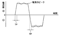
- the sine wave refers to that shown in FIG.
- a trapezoidal wave means what was shown in FIG. In this trapezoidal wave, the time (TP) until the current reaches a peak from zero is preferably 0.5 to 3 msec.
- TP exceeds 3 msec, especially when an aqueous solution containing nitric acid is used, it becomes susceptible to the influence of trace components in the electrolytic solution typified by ammonium ions and the like that spontaneously increase by electrolytic treatment, and uniform graining. Is difficult to be performed. As a result, the stain resistance tends to decrease when a lithographic printing plate is obtained.
- An AC duty ratio of 1: 2 to 2: 1 can be used. However, as described in Japanese Patent Application Laid-Open No. 5-195300, in an indirect power feeding method in which no conductor roll is used for aluminum, the duty ratio is used. Is preferably 1: 1.
- An AC frequency of 0.1 to 120 Hz can be used, but 50 to 70 Hz is preferable in terms of equipment. If it is lower than 50 Hz, the carbon electrode of the main electrode is likely to be dissolved, and if it is higher than 70 Hz, it is likely to be affected by the inductance component on the power supply circuit and the power supply cost is increased.
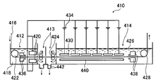
- FIG. 2 is a side view showing an example of a radial type cell used for electrochemical surface roughening using alternating current.
- One or more AC power supplies can be connected to the electrolytic cell.
- uniform graining, and dissolving the carbon of the main electrode are shown in FIG.
- 11 is an aluminum alloy plate
- 12 is a radial drum roller
- 13a and 13b are main poles
- 14 is an electrolytic treatment liquid
- 15 is an electrolytic solution supply port
- 16 is a slit.
- 17 is an electrolyte passage
- 18 is an auxiliary anode
- 19a and 19b are thyristors
- 20 is an AC power source
- 40 is a main electrolytic cell
- 50 is an auxiliary anode cell.
- An anode acting on the aluminum alloy plate facing the main electrode by diverting a part of the current value as a direct current to an auxiliary anode provided in a tank separate from the two main electrodes via a rectifying element or a switching element
- the ratio of the current value involved in the reaction to the current value involved in the cathode reaction can be controlled.
- the ratio of the amount of electricity involved in the anodic reaction and the cathodic reaction is preferably 0.3 to 0.95.
- electrolytic cell electrolytic cells used for known surface treatments such as a vertical type, a flat type, and a radial type can be used, but a radial type electrolytic cell as described in JP-A-5-195300 is particularly preferable.
- the electrolytic solution passing through the electrolytic cell may be parallel to the traveling direction of the aluminum web or may be a counter.
- an electrolytic solution used for the electrochemical surface roughening treatment using ordinary direct current can be used.
- the same electrolyte solution used for the electrochemical surface roughening treatment using the alternating current can be used.
- the DC power source wave used for the electrochemical surface roughening treatment is not particularly limited as long as the current does not change in polarity. Smoothed continuous direct current is preferred.
- the electrochemical surface roughening treatment using direct current can be performed by any of a batch method, a semi-continuous method and a continuous method, but is preferably performed by a continuous method.
- the apparatus used for the electrochemical surface roughening treatment using direct current applies a direct current voltage between anodes and cathodes arranged alternately, and an aluminum alloy plate is spaced from the anode and cathode. If it can be passed, it will not be specifically limited.
- An electrode is not specifically limited, The conventionally well-known electrode used for an electrochemical roughening process can be used.
- a valve metal such as titanium, tantalum, or niobium is plated or clad with a platinum group metal; the valve metal is coated with an oxide of a platinum group metal or sintered. Aluminium; stainless steel. Among these, a valve metal obtained by cladding platinum is preferable.
- the life of the anode can be further extended by a method such as passing water through the electrode to cool it.
- a metal that does not dissolve when the electrode potential is negative can be selected and used from the Boolean Bay diagram. Among these, carbon is preferable.
- the electrode arrangement can be appropriately selected according to the wave structure.
- the structure can be adjusted.
- the electrolysis conditions of each treatment tank can be changed.
- the first electrolytic surface roughening treatment After the first electrolytic surface roughening treatment is completed, it is preferable to drain the liquid with a nip roller, and further perform the water washing treatment for 1 to 10 seconds and then drain the liquid with a nip roller.
- the washing treatment is preferably carried out using a spray tube.
- a spray tube used for the water washing treatment for example, a spray tube having a plurality of spray tips in the width direction of the aluminum alloy plate in which spray water spreads in a fan shape can be used.
- the interval between spray tips is preferably 20 to 100 mm, and the amount of liquid per spray tip is preferably 1 to 20 L / min. It is preferable to use a plurality of spray tubes.
- the second alkaline etching process performed between the first electrolytic surface roughening process and the second electrolytic surface roughening process includes dissolving the smut generated in the first electrolytic surface roughening process, and the first electrolytic roughing process. This is performed for the purpose of dissolving the edge portion of the pit formed by the surface treatment. As a result, the edge portion of the large pit formed by the first electrolytic surface roughening treatment is melted and the surface becomes smooth, so that the ink is not easily caught on the edge portion. Obtainable. Since the second alkali etching process is basically the same as the first alkali etching process, only different points will be described below.
- the etching amount is preferably at 0.05 g / m 2 or more, more preferably 0.1 g / m 2 or more, and it is at 4g / m 2 or less Preferably, it is 3.5 g / m 2 or less.
- the etching amount is 0.05 g / m 2 or more, in the non-image portion of the lithographic printing plate, the edge portion of the pit generated by the first electrolytic surface-roughening treatment becomes smooth and the ink is difficult to be caught. Excellent in properties.
- the etching amount is 4 g / m 2 or less, the unevenness generated by the first electrolytic surface roughening treatment becomes large, so that the printing durability is excellent.
- the concentration of the alkali solution is preferably 30 g / L or more, more preferably 300 g / L or more, and preferably 500 g / L or less, 450 g / L.
- the alkaline solution preferably contains aluminum ions.
- the aluminum ion concentration is preferably 1 g / L or more, more preferably 50 g / L or more, and preferably 200 g / L or less, more preferably 150 g / L or less.
- Such an alkaline solution can be prepared using, for example, water, a 48 mass% sodium hydroxide aqueous solution, and sodium aluminate.
- nitric acid or sulfuric acid is preferably used.
- an acidic solution containing 1 to 400 g / L of acid and 0.1 to 8 g / L of aluminum ions In the case of using sulfuric acid, specifically, a solution prepared by dissolving aluminum sulfate in a sulfuric acid aqueous solution having a sulfuric acid concentration of 100 to 350 g / L to adjust the aluminum ion concentration to 0.1 to 5 g / L is used. Can do.
- the overflow waste liquid of the electrolyte solution used for the anodizing process mentioned later can also be used.
- the treatment time is preferably 1 second or more, more preferably 4 seconds or more, and preferably 60 seconds or less, more preferably 20 seconds or less.
- the temperature of the acid aqueous solution is preferably 20 ° C. or higher, more preferably 30 ° C. or higher, and preferably 70 ° C. or lower, and preferably 60 ° C. or lower. More preferred.
- the second electrolytic surface roughening treatment is an electrochemical surface roughening treatment using alternating current or direct current in an aqueous solution containing hydrochloric acid.
- first electrolytic surface roughening treatment described above may be used, but by combining this second electrolytic surface roughening treatment, a more complicated uneven structure is formed on the surface of the aluminum alloy plate. As a result, the printing durability can be improved.
- the second electrolytic surface roughening treatment is basically the same as the hydrochloric acid electrolysis described in the first electrolytic surface roughening treatment.
- the total amount of electricity that the aluminum alloy plate takes part in the anodic reaction by electrochemical surface roughening in an aqueous solution containing hydrochloric acid in the second electrolytic surface roughening treatment is the time when the electrochemical surface roughening treatment is completed. in may be selected from the range of 10 ⁇ 200C / dm 2, in order not to destroying large rough surface formed by the first electrolytic graining treatment is preferably 10 ⁇ 100C / dm 2, is 50 ⁇ 80C / dm 2 Particularly preferred.
- Second hydrochloric acid electrolysis in which the total amount of electricity in the anodic reaction is 25 to 100 C / dm 2 in an electrolytic solution containing hydrochloric acid, and alkaline etching treatment in which the dissolution amount is 0.03 g / m 2 or more. It is preferable to apply in order. By roughening with this combination, a lithographic printing plate precursor having better stain resistance and printing durability can be obtained.
- the third alkali etching process performed after the second electrolytic surface roughening process involves dissolving the smut generated by the second electrolytic surface roughening process, and the edge of the pit formed by the second electrolytic surface roughening process. This is done for the purpose of dissolving the part. Since the third alkali etching process is basically the same as the first alkali etching process, only different points will be described below.
- the etching amount is preferably at 0.05 g / m 2 or more, more preferably 0.1 g / m 2 or more, is 0.3 g / m 2 or less Of 0.25 g / m 2 or less is more preferable.
- the etching amount is 0.05 g / m 2 or more, in the non-image portion of the lithographic printing plate, the edge portion of the pit generated by the second hydrochloric acid electrolysis becomes smooth and the ink is not easily caught, so that the stain resistance is excellent.
- the etching amount is 0.3 g / m 2 or less, the unevenness generated by the first electrolytic surface roughening treatment and the second electrolytic surface roughening treatment becomes large, so that the printing durability is excellent.
- the concentration of the alkaline solution is preferably 30 g / L or more, and in order not to make the unevenness caused by the hydrochloric acid alternating current electrolysis in the previous stage too small, the concentration is 100 g / L or less. It is preferable that it is 70 g / L or less.
- the alkaline solution preferably contains aluminum ions.
- the aluminum ion concentration is preferably 1 g / L or more, more preferably 3 g / L or more, and preferably 50 g / L or less, more preferably 8 g / L or less.
- Such an alkaline solution can be prepared using, for example, water, a 48 mass% sodium hydroxide aqueous solution, and sodium aluminate.
- the temperature of the alkaline solution is preferably 25 ° C or higher, more preferably 30 ° C or higher, and preferably 60 ° C or lower, and 50 ° C or lower. Is more preferable.
- the treatment time is preferably 1 second or longer, more preferably 2 seconds or longer, more preferably 30 seconds or shorter, and more preferably 10 seconds or shorter. preferable.
- pickling is preferably performed to remove dirt (smut) remaining on the surface. Since the third desmut process is basically the same as the first desmut process, only the differences will be described below.
- the third desmutting treatment it is preferable to use an acidic solution containing 5 to 400 g / L of acid and 0.5 to 8 g / L of aluminum ions.
- sulfuric acid specifically, a solution prepared by dissolving aluminum sulfate in a sulfuric acid aqueous solution having a sulfuric acid concentration of 100 to 350 g / L to adjust the aluminum ion concentration to 1 to 5 g / L is preferable.
- the treatment time is preferably 1 second or longer, more preferably 4 seconds or longer, more preferably 60 seconds or shorter, and more preferably 15 seconds or shorter.
- the draining with a nip roller and the water washing process can be omitted after the desmut process.
- anodizing treatment can be performed by a method conventionally used in this field.
- an anodized film can be formed by energizing an aluminum alloy plate as an anode in a solution having a sulfuric acid concentration of 50 to 300 g / L and an aluminum concentration of 5% by mass or less.
- sulfuric acid, phosphoric acid, chromic acid, oxalic acid, sulfamic acid, benzenesulfonic acid, amidosulfonic acid and the like can be used alone or in combination of two or more.
- anodizing treatment using sulfuric acid or phosphoric acid aqueous solution is preferable.
- the second and third components may be added.
- the second and third components herein include metal ions such as Na, K, Mg, Li, Ca, Ti, Al, V, Cr, Mn, Fe, Co, Ni, Cu, and Zn; Cation such as ammonium ion; anion such as nitrate ion, carbonate ion, chloride ion, phosphate ion, fluoride ion, sulfite ion, titanate ion, silicate ion, borate ion, etc., 0 to 10,000 ppm It may be contained at a concentration of about.
- the conditions for anodizing treatment vary depending on the electrolyte used, and thus cannot be determined unconditionally. In general, however, the electrolyte concentration is 1 to 80% by mass, the solution temperature is 5 to 70 ° C., and the current density is 0.5. It is appropriate that ⁇ 60 A / dm 2 , voltage 1 ⁇ 100 V, and electrolysis time 15 seconds ⁇ 50 minutes, which are adjusted so as to obtain a desired anodic oxide film amount.
- the methods described in JP-A-207299, JP-A-5-24377, JP-A-5-32083, JP-A-5-125597, JP-A-5-195291 and the like can also be used.
- a sulfuric acid solution as the electrolytic solution.
- the sulfuric acid concentration in the electrolytic solution is preferably 10 to 300 g / L (1 to 30% by mass), more preferably 50 to 200 g / L (5 to 20% by mass), and the aluminum ion concentration Is preferably 1 to 25 g / L (0.1 to 2.5% by mass), more preferably 2 to 10 g / L (0.2 to 1% by mass).
- Such an electrolytic solution can be prepared, for example, by adding aluminum sulfate or the like to dilute sulfuric acid having a sulfuric acid concentration of 50 to 200 g / L.
- composition management of the electrolyte is conducted using the same method as in the case of nitric acid electrolysis described above, and the conductivity, specific gravity and temperature, or conductivity and ultrasonic wave propagation corresponding to the matrix of sulfuric acid concentration and aluminum ion concentration. It is preferable to control by speed and temperature.
- the liquid temperature of the electrolytic solution is preferably 25 to 55 ° C, more preferably 30 to 50 ° C.
- a direct current may be applied between the aluminum alloy plate and the counter electrode, or an alternating current may be applied.
- the current density is preferably 1 to 60 A / dm 2 , and more preferably 5 to 40 A / dm 2 .
- the current density it is preferable to increase the current density to 30 to 50 A / dm 2 or higher as the anodic oxidation process proceeds by applying a current at a low current density of 5 to 10 A / m 2 .
- the current distribution of the DC power supply is set so that the current of the downstream DC power supply is equal to or greater than the current of the upstream DC power supply.
- the average pore diameter is about 5 to 50 nm, and the average pore density is 300. It is about 800 / ⁇ m 2 .
- the amount of the anodized film is preferably 1.0 ⁇ m or more, more preferably 1.3 ⁇ m or more, and further preferably 2 ⁇ m or more. It is preferably 1 to 5 g / m 2 . If it is less than 1 g / m 2 , the plate tends to be damaged, whereas if it exceeds 5 g / m 2 , a large amount of electric power is required for production, which is economically disadvantageous.
- the amount of the anodized film is more preferably 1.5 to 4 g / m 2 . Further, it is preferable that the difference in the amount of the anodized film between the center portion of the aluminum alloy plate and the vicinity of the edge portion is 1 g / m 2 or less.
- FIG. 3 is a schematic view showing an example of an apparatus for anodizing the surface of an aluminum alloy plate.
- the feeding tank 412 is upstream of the aluminum alloy plate 416 in the traveling direction, and the anodizing tank is downstream. 414 is installed.
- Aluminum alloy plate 416 is conveyed by pass rollers 422 and 428 as indicated by arrows in FIG.
- an anode 420 connected to the positive electrode of the DC power supply 434 is installed, and the aluminum alloy plate 416 serves as a cathode. Therefore, a cathode reaction occurs in the aluminum alloy plate 416.
- a cathode 430 connected to the negative electrode of the DC power source 434 is installed, and the aluminum alloy plate 416 serves as an anode. Therefore, an anodic reaction occurs in the aluminum alloy plate 416, and an anodized film is formed on the surface of the aluminum alloy plate 416.
- the distance between the aluminum alloy plate 416 and the cathode 430 is preferably 50 to 200 mm.
- Aluminum is used as the cathode 430.
- the cathode 430 is not an electrode having a large area but an electrode divided into a plurality of pieces in the traveling direction of the aluminum alloy plate 416 so that the hydrogen gas generated by the anode reaction can easily escape from the system. preferable.
- an intermediate tank 413 in which the electrolytic solution does not accumulate between the power supply tank 412 and the anodizing treatment tank 414.
- the intermediate tank 413 it is possible to prevent the current from bypassing the anode 420 to the cathode 430 without passing through the aluminum alloy plate 416. It is preferable to reduce the bypass current as much as possible by installing a nip roller 424 in the intermediate tank 413 to drain the liquid. The electrolyte discharged by draining is discharged out of the anodizing apparatus 410 from the drain port 442.
- the electrolyte solution 418 stored in the power supply tank 412 has a higher temperature and / or higher concentration than the electrolyte solution 426 stored in the anodizing tank 414 in order to reduce voltage loss.
- the composition, temperature, and the like of the electrolytic solutions 418 and 426 are determined from the formation efficiency of the anodized film, the micropore shape of the anodized film, the hardness of the anodized film, the voltage, the cost of the electrolytic solution, and the like.
- the electrolytic solution is ejected from the liquid supply nozzles 436 and 438 and supplied to the power supply tank 412 and the anodizing treatment tank 414.
- the liquid supply nozzles 436 and 438 are provided with slits, and the ejected liquid flow is changed in the width direction. It has a structure that makes it constant.
- a shielding plate 440 is provided on the opposite side of the aluminum alloy plate 416 from the anode 430, and current flows on the opposite side of the surface of the aluminum alloy plate 416 where the anodized film is to be formed. Suppresses
- the distance between the aluminum alloy plate 416 and the shielding plate 440 is preferably 5 to 30 mm. It is preferable to use a plurality of DC power supplies 434 and connect the positive electrode sides in common. Thereby, the current distribution in the anodizing bath 414 can be controlled.
- a sealing treatment for sealing the micropores present in the anodized film may be performed as necessary.
- the sealing treatment can be performed according to a known method such as boiling water treatment, hot water treatment, steam treatment, sodium silicate treatment, nitrite treatment, ammonium acetate treatment and the like.
- a known method such as boiling water treatment, hot water treatment, steam treatment, sodium silicate treatment, nitrite treatment, ammonium acetate treatment and the like.
- the sealing treatment is performed by the apparatus and method described in JP-B-56-12518, JP-A-4-4194, JP-A-5-20296, JP-A-5-179482, etc. Good.
- a hydrophilization treatment may be performed after the anodizing treatment or the sealing treatment.
- the hydrophilization treatment include treatment with potassium fluorozirconate described in US Pat. No. 2,946,638 and phosphomolybdate described in US Pat. No. 3,201,247.
- treatment alkyl titanate treatment described in British Patent 1,108,559, polyacrylic acid treatment described in German Patent 1,091,433, German Patent 1,134, No. 093 and British Patent No. 1,230,447, polyvinyl phosphonic acid treatment, Japanese Patent Publication No. 44-6409, phosphonic acid treatment, US Pat. No. 3,307,951 Phytic acid treatment described in the specification of JP, No.
- phosphates described in JP-A-62-019494, water-soluble epoxy compounds described in JP-A-62-033692, and JP-A-62-097892 Phosphate-modified starch diamine compounds described in JP-A-63-056498, amino acid inorganic or organic acids described in JP-A-63-130391, JP-A-63-145092 Organic phosphonic acids containing a carboxy group or a hydroxy group, compounds having an amino group and a phosphonic acid group described in JP-A-63-165183, and JP-A-2-316290
- Specific carboxylic acid derivatives, phosphate esters described in JP-A-3-215095, JP-A-3-261592 Compounds having one amino group and one oxygen acid group of phosphorus described in the publication, phosphate esters described in JP-A-3-215095, and JP-A-5-246171 Aliphatic or aromatic phosphonic acids such as phenylphosphonic acid, compounds containing S
- hydrophilic vinyl polymers such as a method of immersion treatment or electrolytic treatment in an aqueous solution of alkali metal silicate such as sodium silicate and potassium silicate, a method of treatment with potassium zirconate fluoride, a method of treatment with polyvinylphosphonic acid, etc.
- the hydrophilic treatment is preferably performed by a method of applying a hydrophilic compound to form a hydrophilic undercoat layer.
- a method of immersing in an aqueous polyvinylphosphonic acid solution is preferably used.
- Hydrophilization treatment with an aqueous solution of an alkali metal silicate such as sodium silicate and potassium silicate is described in US Pat. No. 2,714,066 and US Pat. No. 3,181,461. It can be performed according to methods and procedures.
- the alkali metal silicate include sodium silicate, potassium silicate, and lithium silicate.
- the aqueous solution of alkali metal silicate may contain an appropriate amount of sodium hydroxide, potassium hydroxide, lithium hydroxide or the like.
- the aqueous solution of alkali metal silicate may contain an alkaline earth metal salt or a Group 4 (Group IVA) metal salt.
- alkaline earth metal salt examples include nitrates such as calcium nitrate, strontium nitrate, magnesium nitrate, and barium nitrate; sulfates; hydrochlorides; phosphates; acetates; oxalates;
- Group 4 (Group IVA) metal salts include titanium tetrachloride, titanium trichloride, potassium titanium fluoride, titanium oxalate, titanium sulfate, titanium tetraiodide, zirconium chloride, zirconium dioxide, zirconium oxychloride. And zirconium tetrachloride. These alkaline earth metal salts and Group 4 (Group IVA) metal salts are used alone or in combination of two or more.
- the amount of Si adsorbed by the alkali metal silicate treatment can be measured with a fluorescent X-ray analyzer, and the amount of adsorption is preferably about 1.0 to 15.0 mg / m 2 .
- the hydrophilization treatment by forming a hydrophilic undercoat layer can also be performed according to the conditions and procedures described in JP-A Nos. 59-101651 and 60-149491.
- the hydrophilic vinyl polymer used in this method include polyvinyl sulfonic acid, a sulfo group-containing vinyl polymerizable compound such as p-styrene sulfonic acid having a sulfo group, and ordinary vinyl polymerization such as (meth) acrylic acid alkyl ester. And a copolymer with a functional compound.
- the hydrophilic compound used in this method include compounds having at least one selected from the group consisting of —NH 2 group, —COOH group and sulfo group.
- ⁇ Dry> After obtaining the support used for the lithographic printing plate precursor according to the first aspect of the present invention by the procedure described above, it is preferable to dry the surface of the support before providing the photosensitive layer on the support. Drying is preferably performed after the final treatment of the surface treatment, after washing with water and draining with a nip roller.
- the drying temperature is preferably 70 ° C or higher, more preferably 80 ° C or higher, preferably 110 ° C or lower, more preferably 100 ° C or lower.
- the drying time is preferably 1 second or more, more preferably 2 seconds or more, and preferably 20 seconds or less, more preferably 15 seconds.
- ⁇ Management of liquid composition> it is preferable to manage the composition of various processing solutions used for the surface treatment described above by the method described in JP-A-2001-121837.
- an electrolytic solution having a sulfuric acid concentration of 250 g / L or more it is preferable to control the concentration by the method described above.
- each electrolyte solution used for an electrolytic roughening process and an anodic oxidation process is 100 ppm or less of Cu concentration. If the Cu concentration is too high, Cu is deposited on the aluminum alloy plate when the line is stopped, and Cu deposited when the line is operated again may be transferred to a pass roll, which may cause processing unevenness.
- the photosensitive layer of the lithographic printing plate precursor according to the first aspect of the present invention comprises (A) a sensitizing dye, (B) a polymerization initiator, (C) a polymerizable compound, and (D) a binder polymer.
- a sensitizing dye for a sensitizing dye
- B for a polymerization initiator
- C for a polymerizable compound
- D for a binder polymer.
- the photosensitive layer of the first embodiment of the present invention contains a sensitizing dye.
- the sensitizing dye is particularly limited as long as it absorbs light at the time of image exposure and enters an excited state, and supplies energy to the polymerization initiator described later by electron transfer, energy transfer, or heat generation to improve the polymerization initiation function. It can be used without.
- a sensitizing dye having a maximum absorption at 300 to 450 nm or 750 to 1400 nm is preferably used.
- Examples of the sensitizing dye having maximum absorption in the wavelength range of 350 to 450 nm include merocyanine dyes, benzopyrans, coumarins, aromatic ketones, anthracenes, and the like.
- a dye more preferable from the viewpoint of high sensitivity is a dye represented by the following general formula (IX).
- A represents an aromatic ring group or a heterocyclic group which may have a substituent
- X represents an oxygen atom, a sulfur atom or N— (R 3 ).
- R 1 , R 2 and R 3 each independently represent a monovalent nonmetallic atomic group, and A and R 1 and R 2 and R 3 are bonded to each other to form an aliphatic or aromatic ring. May be formed.
- R 1 , R 2 and R 3 are each independently a monovalent nonmetallic atomic group, preferably a substituted or unsubstituted alkyl group, a substituted or unsubstituted alkenyl group, a substituted or unsubstituted aryl group. Represents a substituted or unsubstituted aromatic heterocyclic residue, a substituted or unsubstituted alkoxy group, a substituted or unsubstituted alkylthio group, a hydroxyl group, and a halogen atom.
- a in the general formula (IX) represents an aromatic ring group or a heterocyclic group which may have a substituent.
- Specific examples of the aromatic ring or heterocyclic ring which may have a substituent include R 1 in the general formula (IX). , R 2 and R 3 are the same.
- sensitizing dyes represented by the following general formulas (V) to (VI) can also be used.
- R 1 to R 14 each independently represents a hydrogen atom, an alkyl group, an alkoxy group, a cyano group or a halogen atom. However, at least one of R 1 to R 10 represents an alkoxy group having 2 or more carbon atoms.
- R 15 to R 32 each independently represents a hydrogen atom, an alkyl group, an alkoxy group, a cyano group or a halogen atom. However, at least one of R 15 to R 24 represents an alkoxy group having 2 or more carbon atoms.
- JP2007-171406, JP2007-206216, JP2007-206217, JP2007-225701, JP2007-225702, JP2007-316582, and JP2007-328243 can be preferably used.
- a sensitizing dye having a maximum absorption at 750 to 1400 nm (hereinafter sometimes referred to as “infrared absorber”) that is preferably used in the first embodiment of the present invention will be described in detail.
- infrared absorber a dye or a pigment is preferably used.
- dyes such as azo dyes, metal complex azo dyes, pyrazolone azo dyes, naphthoquinone dyes, anthraquinone dyes, phthalocyanine dyes, carbonium dyes, quinoneimine dyes, methine dyes, cyanine dyes, squarylium dyes, pyrylium salts, metal thiolate complexes, etc. Is mentioned.
- cyanine dyes particularly preferred among these dyes are cyanine dyes, squarylium dyes, pyrylium salts, nickel thiolate complexes, and indolenine cyanine dyes. Further, cyanine dyes and indolenine cyanine dyes are preferred, and particularly preferred examples include cyanine dyes represented by the following general formula (a).
- X 1 represents a hydrogen atom, a halogen atom, -N (Ph) 2 , -X 2 -L 1 or a group shown below.
- Ph represents a phenyl group
- X 2 represents an oxygen atom, a nitrogen atom or a sulfur atom
- L 1 represents a hydrocarbon group having 1 to 12 carbon atoms, a hetero atom (N, S, O, halogen atom, Se And a hydrocarbon group having 1 to 12 carbon atoms including a hetero atom.
- Xa ⁇ is defined in the same manner as Za ⁇ described later, and R a represents a substituent selected from a hydrogen atom, an alkyl group, an aryl group, a substituted or unsubstituted amino group, and a halogen atom. .
- R 1 and R 2 each independently represents a hydrocarbon group having 1 to 12 carbon atoms. From the storage stability of the photosensitive layer coating solution, R 1 and R 2 are preferably hydrocarbon groups having 2 or more carbon atoms, and R 1 and R 2 are bonded to each other to form a 5-membered ring or It is particularly preferable that a 6-membered ring is formed.
- Ar 1 and Ar 2 may be the same or different and each represents an aromatic hydrocarbon group which may have a substituent.
- Preferred aromatic hydrocarbon groups include a benzene ring and a naphthalene ring.
- a C12 or less hydrocarbon group, a halogen atom, and a C12 or less alkoxy group are mentioned.
- Y 1 and Y 2 may be the same or different and each represents a sulfur atom or a dialkylmethylene group having 12 or less carbon atoms.
- R 3 and R 4 may be the same or different and each represents a hydrocarbon group having 20 or less carbon atoms, which may have a substituent.
- Preferred substituents include alkoxy groups having 12 or less carbon atoms, carboxy groups, and sulfo groups.
- R 5 , R 6 , R 7 and R 8 may be the same or different and each represents a hydrogen atom or a hydrocarbon group having 12 or less carbon atoms. From the availability of raw materials, a hydrogen atom is preferred.
- Za ⁇ represents a counter anion. However, Za ⁇ is not necessary when the cyanine dye represented by formula (a) has an anionic substituent in its structure and neutralization of charge is not necessary.
- Preferred Za ⁇ is a halide ion, a perchlorate ion, a tetrafluoroborate ion, a hexafluorophosphate ion, and a sulfonate ion, particularly preferably a perchlorate ion, in view of the storage stability of the photosensitive layer coating solution.
- Specific examples of the cyanine dye represented by the general formula (a) that can be suitably used in the first embodiment of the present invention include paragraph numbers [0017] to [0019] of JP-A No. 2001-133969, JP Examples thereof include those described in paragraph numbers [0012] to [0021] of JP 2002-023360 A and paragraph numbers [0012] to [0037] of JP 2002040406 A2.
- pigments examples include commercially available pigment and color index (CI) manuals, “Latest Pigment Handbook” (edited by the Japan Pigment Technology Association, published in 1977), “Latest Pigment Applied Technology” (published by CMC, published in 1986), “Printing” The pigments described in "Ink Technology”, published by CMC Publishing, 1984) can be used.
- CI pigment and color index
- the compounds described in JP 2008-195018 A [0072] to [0076] are preferable.
- the preferred addition amount of these sensitizing dyes is preferably 0.05 to 30% by mass, more preferably 0.1 to 20% by mass, and most preferably 0.2 to 10% by mass with respect to the total solid content of the photosensitive layer. Range.
- the photosensitive layer of the first embodiment of the present invention contains a polymerization initiator (hereinafter also referred to as an initiator compound).
- a radical polymerization initiator is preferably used.
- the initiator compound in the first embodiment of the present invention those known to those skilled in the art can be used without limitation, and specifically include, for example, trihalomethyl compounds, carbonyl compounds, organic peroxides, azo compounds, azides.
- examples thereof include compounds, metallocene compounds, hexaarylbiimidazole compounds, organic boron compounds, disulfone compounds, oxime ester compounds, onium salt compounds, and iron arene complexes.
- at least one selected from the group consisting of hexaarylbiimidazole compounds, onium salts, trihalomethyl compounds, and metallocene compounds is preferable, and hexaarylbiimidazole compounds are particularly preferable.
- Two or more of the above polymerization initiators can be used in combination as appropriate.
- hexaarylbiimidazole compounds examples include lophine dimers described in JP-B Nos. 45-37377 and 44-86516, such as 2,2′-bis (o-chlorophenyl) -4,4 ′, 5.
- the onium salt suitably used in the first embodiment of the present invention is preferably a sulfonium salt, an iodonium salt, or a diazonium salt.
- diaryliodonium salts and triarylsulfonium salts are preferably used.
- the onium salt is particularly preferably used in combination with an infrared absorber having a maximum absorption at 750 to 1400 nm.
- polymerization initiators described in JP-A-2007-206217 [0071] to [0129] can be preferably used.
- the polymerization initiator in the first embodiment of the present invention is suitably used alone or in combination of two or more.
- the amount of the polymerization initiator used in the photosensitive layer in the first embodiment of the present invention is preferably 0.01 to 20% by mass, more preferably 0.1 to 15% by mass, based on the total solid content of the photosensitive layer. . More preferably, the content is 1.0% by mass to 10% by mass.
- the polymerizable compound that can be used in the first embodiment of the present invention is an addition polymerizable compound having at least one ethylenically unsaturated double bond, and has at least one terminal ethylenically unsaturated bond.
- it is selected from compounds having two or more, preferably two or more. These have chemical forms such as monomers, prepolymers, ie dimers, trimers and oligomers, or mixtures thereof.
- Examples of monomers include unsaturated carboxylic acids (for example, acrylic acid, methacrylic acid, itaconic acid, crotonic acid, isocrotonic acid, maleic acid, etc.), esters and amides thereof, preferably unsaturated carboxylic acids.
- unsaturated carboxylic acids for example, acrylic acid, methacrylic acid, itaconic acid, crotonic acid, isocrotonic acid, maleic acid, etc.
- esters and amides thereof preferably unsaturated carboxylic acids.
- An ester of an acid and a polyhydric alcohol compound and an amide of an unsaturated carboxylic acid and a polyvalent amine compound are used.
- a dehydration condensation reaction product with a functional carboxylic acid is also preferably used.
- a substitution reaction product of an unsaturated carboxylic acid ester or amide having a leaving substituent such as a tosyloxy group and a monofunctional or polyfunctional alcohol, amine or thiol is also suitable.
- monomers of esters of polyhydric alcohol compounds and unsaturated carboxylic acids include acrylic acid esters such as ethylene glycol diacrylate, 1,3-butanediol diacrylate, tetramethylene glycol diacrylate, propylene glycol diacrylate, Examples include trimethylolpropane triacrylate, hexanediol diacrylate, tetraethylene glycol diacrylate, pentaerythritol tetraacrylate, sorbitol triacrylate, isocyanuric acid ethylene oxide (EO) -modified triacrylate, and polyester acrylate oligomer.
- acrylic acid esters such as ethylene glycol diacrylate, 1,3-butanediol diacrylate, tetramethylene glycol diacrylate, propylene glycol diacrylate
- Examples include trimethylolpropane triacrylate, hexanediol diacrylate, tetraethylene glycol diacrylate, pentaery
- Methacrylic acid esters include tetramethylene glycol dimethacrylate, neopentyl glycol dimethacrylate, trimethylolpropane trimethacrylate, ethylene glycol dimethacrylate, pentaerythritol trimethacrylate, bis [p- (3-methacryloxy-2-hydroxypropoxy) phenyl ] Dimethylmethane, bis- [p- (methacryloxyethoxy) phenyl] dimethylmethane, and the like.
- amide monomers of polyvalent amine compounds and unsaturated carboxylic acids include methylene bis-acrylamide, methylene bis-methacrylamide, 1,6-hexamethylene bis-acrylamide, 1,6-hexamethylene bis-methacrylic.
- examples include amide, diethylenetriamine trisacrylamide, xylylene bisacrylamide, and xylylene bismethacrylamide.
- urethane-based addition-polymerizable compounds produced by using an addition reaction of isocyanate and hydroxyl group are also suitable. Specific examples thereof include, for example, one molecule described in JP-B-48-41708.
- a vinylurethane compound containing two or more polymerizable vinyl groups in one molecule obtained by adding a vinyl monomer containing a hydroxyl group represented by the following general formula (A) to a polyisocyanate compound having two or more isocyanate groups Etc.
- R 4 and R 5 represent H or CH 3 .
- urethane acrylates as described in JP-A-51-37193, JP-B-2-32293, JP-B-2-16765, JP-B-58-49860, JP-B-56- Urethane compounds having an ethylene oxide skeleton described in Japanese Patent No. 17654, Japanese Patent Publication No. 62-39417, and Japanese Patent Publication No. 62-39418 are also suitable.
- photo-oxidizable polymerizable compounds described in JP-T-2007-506125 are suitable, and polymerizable compounds containing at least one urea group and / or tertiary amino group are particularly preferred. Specific examples include the following compounds.
- the details of the method of use such as the structure of these polymerizable compounds, whether they are used alone or in combination, and the amount added can be arbitrarily set according to the performance design of the final planographic printing plate precursor.
- the polymerizable compound is preferably used in the range of 5 to 75% by mass, more preferably 25 to 70% by mass, and particularly preferably 30 to 60% by mass with respect to the total solid content of the photosensitive layer.
- the photosensitive layer of the first embodiment of the present invention has a binder polymer.
- the binder polymer one that can carry the photosensitive layer component on a support and can be removed by a developer is used.
- the binder polymer (meth) acrylic polymer, polyurethane resin, polyvinyl alcohol resin, polyvinyl butyral resin, polyvinyl formal resin, polyamide resin, polyester resin, epoxy resin and the like are used.
- (meth) acrylic polymers, polyurethane resins, and polyvinyl butyral resins are preferably used.
- (meth) acrylic polymer refers to (meth) acrylic acid, (meth) acrylic acid ester (alkyl ester, aryl ester, allyl ester, etc.), (meth) acrylamide, And a copolymer having a (meth) acrylic acid derivative such as a (meth) acrylamide derivative as a polymerization component.
- Polyurethane resin refers to a polymer produced by a condensation reaction of a compound having two or more isocyanate groups and a compound having two or more hydroxyl groups.
- Polyvinyl butyral resin refers to a polymer synthesized by reacting polyvinyl alcohol obtained by saponifying part or all of polyvinyl acetate and butyraldehyde under an acidic condition (acetalization reaction), Polymers having an acid group or the like introduced by a method of reacting a compound having a remaining hydroxy group and an acid group or the like are also included.
- a suitable example of the binder polymer in the first aspect of the present invention includes a copolymer having a repeating unit containing an acid group.
- the acid group include a carboxylic acid group, a sulfonic acid group, a phosphonic acid group, a phosphoric acid group, and a sulfonamide group, but a carboxylic acid group is particularly preferable, and a repeating unit derived from (meth) acrylic acid or the following general formula Those represented by (I) are preferably used.
- R 1 represents a hydrogen atom or a methyl group
- R 2 represents a single bond or an n + 1 valent linking group
- A represents an oxygen atom or —NR 3 —
- R 3 represents a hydrogen atom or a monovalent hydrocarbon group having 1 to 10 carbon atoms.
- n represents an integer of 1 to 5.
- the linking group represented by R 2 in the general formula (I) is composed of a hydrogen atom, an oxygen atom, a nitrogen atom, a sulfur atom and a halogen atom, and the number of atoms is preferably 1 to 80.
- Specific examples include alkylene, substituted alkylene, arylene, substituted arylene, and the like, and a structure in which a plurality of these divalent groups are linked by an amide bond or an ester bond may be used.
- R 2 is preferably a single bond, alkylene, or substituted alkylene, particularly preferably a single bond, alkylene having 1 to 5 carbon atoms, or substituted alkylene having 1 to 5 carbon atoms.
- alkylene having 3 to 3 and substituted alkylene having 1 to 3 carbon atoms are preferred.
- substituents include a monovalent nonmetallic atomic group excluding a hydrogen atom, a halogen atom (—F, —Br, —Cl, —I), a hydroxyl group, an alkoxy group, an aryloxy group, a mercapto group, An acyl group, a carboxyl group and its conjugate base group, an alkoxycarbonyl group, an aryloxycarbonyl group, a carbamoyl group, an aryl group, an alkenyl group, an alkynyl group and the like can be mentioned.
- R 3 is preferably a hydrogen atom or a hydrocarbon group having 1 to 5 carbon atoms, particularly preferably a hydrogen atom or a hydrocarbon group having 1 to 3 carbon atoms, and most preferably a hydrogen atom or a methyl group.
- n is preferably 1 to 3, particularly preferably 1 or 2, and most preferably 1.
- the proportion (mol%) of the copolymer component having a carboxylic acid group in the total copolymer components of the binder polymer is preferably 1 to 70% from the viewpoint of developability. Considering compatibility between developability and printing durability, it is more preferably 1 to 50%, and particularly preferably 1 to 30%.
- Preferable specific examples of the carboxylic acid group-containing unit include the following examples.
- the acid group of the polymer containing an acid group which is a suitable example of the binder polymer in the first embodiment of the present invention, may be neutralized with a basic compound, and in particular, an amino group, an amidine group, a guanidine. It is preferably neutralized with a compound containing basic nitrogen such as a group. Furthermore, it is also preferable that the compound containing basic nitrogen has an ethylenically unsaturated group. Specific examples of the compound include compounds described in WO2007 / 057442.
- a copolymer of (meth) acrylic acid and (meth) acrylic acid alkyl ester is preferably used.
- a copolymer of (meth) acrylic acid and (meth) acrylic acid methyl ester is preferably used.
- the binder polymer used in the first embodiment of the present invention preferably further has a crosslinkable group.
- the crosslinkable group is a group that crosslinks the binder polymer in the process of radical polymerization reaction that occurs in the photosensitive layer when the lithographic printing plate precursor is exposed.
- it will not specifically limit if it is a group of such a function, For example, an ethylenically unsaturated bond group, an amino group, an epoxy group etc. are mentioned as a functional group which can be addition-polymerized.
- the functional group which can become a radical by light irradiation may be sufficient, and as such a crosslinkable group, a thiol group, a halogen group, etc. are mentioned, for example.
- an ethylenically unsaturated bond group is preferable.
- a styryl group, a (meth) acryloyl group, and an allyl group are preferable.
- free radicals polymerization initiating radicals or growth radicals in the polymerization process of a polymerizable compound
- addition polymerization is performed directly between polymers or through a polymerization chain of the polymerizable compound.
- a cross-link is formed between the polymer molecules and cured.
- atoms in the polymer eg, hydrogen atoms on carbon atoms adjacent to the functional bridging group
- free radicals are abstracted by free radicals to form polymer radicals that are bonded to each other so that crosslinking between the polymer molecules occurs. Forms and cures.
- the content of the crosslinkable group in the binder polymer is preferably 0.01 to 10.0 mmol, more preferably 0.05, per 1 g of the binder polymer. ⁇ 5.0 mmol, most preferably 0.1-2.0 mmol.
- the binder polymer used in the first embodiment of the present invention may have a polymer unit of an alkyl (meth) acrylate or an aralkyl ester in addition to the polymer unit having an acid group and a polymer unit having a crosslinkable group.
- the alkyl group of the (meth) acrylic acid alkyl ester is preferably an alkyl group having 1 to 5 carbon atoms, and more preferably a methyl group.
- Examples of (meth) acrylic acid aralkyl esters include benzyl (meth) acrylate.
- the binder polymer preferably has a mass average molecular weight of 5,000 or more, more preferably 10,000 to 300,000, and a number average molecular weight of 1,000 or more, preferably 2,000 to 250,000. More preferred.
- the polydispersity (mass average molecular weight / number average molecular weight) is preferably 1.1 to 10.
- a binder polymer may be used independently or may be used in mixture of 2 or more types.
- the content of the binder polymer is preferably from 5 to 75% by weight, more preferably from 10 to 70% by weight, more preferably from 10 to 70% by weight, based on the total solid content of the photosensitive layer, from the viewpoint of good image area strength and image formability. More preferably, it is 60 mass%.
- the total content of the polymerizable compound and the binder polymer is preferably 80% by mass or less based on the total solid content of the photosensitive layer. If it exceeds 80% by mass, the sensitivity and developability may be lowered. More preferably, it is 35 to 75% by mass.
- the mass ratio of radically polymerizable compound / binder polymer in the photosensitive layer is preferably 1.2 or more, more preferably 1.25 to 4.5, and most preferably 2 to 4.
- the photosensitive layer preferably further contains a chain transfer agent.
- a chain transfer agent for example, a compound group having SH, PH, SiH, and GeH in the molecule is used. These can donate hydrogen to low-activity radical species to generate radicals, or can be oxidized and then deprotonated to generate radicals.
- thiol compounds for example, 2-mercaptobenzimidazoles, 2-mercaptobenzthiazoles, 2-mercaptobenzoxazoles, 3-mercaptotriazoles, 5-mercaptotetrazole) Etc.
- the photosensitive layer of the first aspect of the present invention can further contain various additives as necessary.
- Additives include surfactants for improving developability and improving the surface of the coating, microcapsules for achieving both developability and printing durability, and improving the developability and dispersion stability of microcapsules.
- Hydrophilic polymer, colorant and print-out agent for visually recognizing image and non-image area polymerization inhibitor for preventing unnecessary thermal polymerization of radically polymerizable compound during production or storage of photosensitive layer, Higher fat derivatives to prevent polymerization inhibition by oxygen, inorganic fine particles to improve the cured film strength of the image area, hydrophilic low molecular weight compounds to improve developability, co-sensitizers and chain transfer to improve sensitivity
- An agent, a plasticizer for improving plasticity, and the like can be added. Any of these compounds can be used, and for example, compounds described in JP-A 2007-206217 [0161] to [0215] can be used.
- the photosensitive layer according to the first aspect of the present invention is formed by preparing or applying a coating solution by dispersing or dissolving the necessary components described above in a solvent.
- a solvent examples include methyl ethyl ketone, ethylene glycol monomethyl ether, 1-methoxy-2-propanol, 2-methoxyethyl acetate, 1-methoxy-2-propyl acetate, and ⁇ -butyllactone.
- the present invention is not limited to this. These solvents are used alone or in combination.
- the solid content concentration of the coating solution is preferably 1 to 50% by mass.
- the photosensitive layer coating amount (solid content) on the support obtained after coating and drying is preferably 0.3 to 3.0 g / m 2 . Within this range, good film properties can be obtained.
- Various methods can be used as a coating method. Examples thereof include bar coater coating, spin coating, spray coating, curtain coating, dip coating, air knife coating, blade coating, and roll coating.
- a protective layer (oxygen blocking layer) is provided on the photosensitive layer in order to block diffusion and penetration of oxygen that hinders the polymerization reaction during exposure.
- a material that can be used for the protective layer for example, it is preferable to use a water-soluble polymer compound having relatively excellent crystallinity.
- polyvinyl alcohol as a main component for oxygen barrier properties and development removability. Gives the best results in terms of basic characteristics.
- the polyvinyl alcohol used for the protective layer may be partially substituted with an ester, an ether, and an acetal as long as it contains an unsubstituted vinyl alcohol unit for having necessary oxygen barrier properties and water solubility. Similarly, some of them may have other copolymer components.
- Polyvinyl alcohol can be obtained by hydrolyzing polyvinyl acetate. Specific examples of polyvinyl alcohol include those having a hydrolysis rate of 71 to 100 mol% and a polymerization repeating unit in the range of 300 to 2400.
- the content of polyvinyl alcohol in the protective layer is 20 to 95% by mass, more preferably 30 to 90% by mass.
- modified polyvinyl alcohol can be preferably used.
- acid-modified polyvinyl alcohol having a carboxylic acid group or a sulfonic acid group is preferably used.
- polyvinyl pyrrolidone or a modified product thereof is preferable from the viewpoint of oxygen barrier property and development removability, and the content in the protective layer is 3.5 to 80% by mass, preferably 10 to 60%. % By mass, more preferably 15 to 30% by mass.
- glycerin, dipropylene glycol and the like can be added in an amount corresponding to several mass% with respect to the (co) polymer to provide flexibility.
- Anionic surfactants such as sodium acid salts; amphoteric surfactants such as alkylaminocarboxylates and alkylaminodicarboxylates; nonionic surfactants such as polyoxyethylene alkylphenyl ethers to the (co) polymer Mass% can be added.
- the protective layer in the lithographic printing plate precursor according to the first aspect of the present invention is described in JP-A-2006-106700 [0018] to [0024] for the purpose of improving oxygen barrier properties and photosensitive layer surface protection. It is also preferable to contain the inorganic layered compound.
- inorganic layered compounds fluorine-based swellable synthetic mica, which is a synthetic inorganic layered compound, is particularly useful.
- the coating amount of the protective layer is preferably in the range of 0.05 to 10 g / m 2 as the coating amount after drying.
- the range of m 2 is more preferable, and when no inorganic layered compound is contained, the range of 0.5 to 5 g / m 2 is more preferable.
- an undercoat layer (sometimes referred to as an intermediate layer) may be provided between the photosensitive layer and the support.
- an undercoat layer having a compound having an acid group such as phosphonic acid, phosphoric acid or sulfonic acid is preferably used. These compounds preferably further contain a polymerizable group in order to improve the adhesion to the photosensitive layer. Furthermore, compounds having a hydrophilicity-imparting group such as an ethylene oxide group can also be mentioned as suitable compounds. These compounds may be low molecular weight or high molecular weight polymers.
- the most preferred undercoat layer there are a crosslinkable group (preferably an ethylenically unsaturated bond group) described in JP-A-2005-238816, JP-A-2005-125649, JP-A-2006-239867, and JP-A-2006-215263, and a support.
- a crosslinkable group preferably an ethylenically unsaturated bond group
- JP-A-2005-125649 ethylenically unsaturated bond group
- JP-A-2006-239867 ethylenically unsaturated bond group
- the coating amount (solid content) of the undercoat layer is preferably 0.1 to 100 mg / m 2 , and more preferably 1 to 30 mg / m 2 .
- a back coat After the surface treatment is performed on the support or after the undercoat layer is formed, a back coat can be provided on the back surface of the support, if necessary.
- the back coat include hydrolysis and polycondensation of an organic polymer compound described in JP-A-5-45885, an organometallic compound or an inorganic metal compound described in JP-A-6-35174.
- a coating layer made of a metal oxide obtained in this way is preferred.
- it is inexpensive to use a silicon alkoxy compound such as Si (OCH 3 ) 4 , Si (OC 2 H 5 ) 4 , Si (OC 3 H 7 ) 4 , Si (OC 4 H 9 ) 4. It is preferable in terms of easy availability.
- the lithographic printing plate precursor according to the first aspect of the present invention is image-exposed and developed to produce a lithographic printing plate.
- Examples of the development treatment include (1) a method of developing with a developer, and (2) a method of developing on a printing press while adding dampening water and / or ink (on-press development).
- On-press development there is no particular limitation.
- the developer used in the plate making method of the lithographic printing plate is not particularly limited.
- the developer contains an inorganic alkali salt and a surfactant and has a pH of 11 to 13 (surfactant and / or water-soluble polymer).
- the inorganic alkali salt can be used as appropriate.
- Inorganic alkaline agents such as sodium carbonate, potassium, ammonium, sodium hydrogencarbonate, potassium, ammonium, sodium borate, potassium, and ammonium. These may be used alone or in combination of two or more.
- the SiO 2 / M 2 O is less than 0.5, it is preferably 1 to 10% by mass, more preferably 3 to 8% by mass, and most preferably 4 to 7% by mass with respect to the mass of the alkaline aqueous solution.
- this concentration is 1% by mass or more, developability and processing capacity are not lowered, and when it is 10% by mass or less, it is difficult to form precipitates and crystals, and further, it is difficult to gel during neutralization in the waste liquid. Does not interfere with waste liquid treatment.
- an organic alkali agent may be supplementarily used for the purpose of finely adjusting the alkali concentration and assisting the solubility of the photosensitive layer.
- the organic alkali agent include monomethylamine, dimethylamine, trimethylamine, monoethylamine, diethylamine, triethylamine, monoisopropylamine, diisopropylamine, triisopropylamine, n-butylamine, monoethanolamine, diethanolamine, triethanolamine, monoisopropanolamine, Examples thereof include diisopropanolamine, ethyleneimine, ethylenediamine, pyridine, tetramethylammonium hydroxide and the like. These alkali agents are used alone or in combination of two or more.
- the surfactant can be used as appropriate, but the anionic surfactant used in the developer of the first aspect of the present invention is not particularly limited, but includes fatty acid salts, abietic acid salts, hydroxyalkanesulfonic acid salts, Alkanesulfonates, dialkylsulfosuccinates, linear alkylbenzenesulfonates, branched alkylbenzenesulfonates, alkylnaphthalenesulfonates, alkyldiphenylether (di) sulfonates, alkylphenoxypolyoxyethylenepropylsulfonates, poly Oxyethylene alkylsulfophenyl ether salts, sodium N-methyl-N-oleyltaurine, disodium N-alkylsulfosuccinic acid monoamide, petroleum sulfonates, sulfated castor oil, sulfated beef tallow oil, Fatty acid alkyl ester sul
- the cationic surfactant used in the developer according to the first aspect of the present invention is not particularly limited, and conventionally known cationic surfactants can be used. Examples thereof include alkylamine salts, quaternary ammonium salts, polyoxyethylene alkylamine salts, and polyethylene polyamine derivatives.
- the nonionic surfactant used in the developer of the first embodiment of the present invention is not particularly limited, but is a polyethylene glycol type higher alcohol ethylene oxide adduct, alkylphenol ethylene oxide adduct, alkyl naphthol ethylene oxide adduct, phenol.
- those having an aromatic ring and an ethylene oxide chain are preferable, and an alkyl-substituted or unsubstituted phenol ethylene oxide adduct or an alkyl-substituted or unsubstituted naphthol ethylene oxide adduct is more preferable.
- the zwitterionic surfactant is not particularly limited, and examples thereof include amine oxides such as alkyldimethylamine oxide, betaines such as alkylbetaines, and amino acids such as alkylamino fatty acid sodium.
- alkyldimethylamine oxide which may have a substituent alkylcarboxybetaine which may have a substituent
- alkylsulfobetaine which may have a substituent are preferably used. Specific examples of these include those described in JP-A-2008-203359 [0255] to [0278], JP-A-2008-276166 [0028] to [0052], and the like.
- Two or more surfactants may be used, and the ratio of the surfactant contained in the developer is preferably 0.01 to 20% by mass, more preferably 0.1 to 10% by mass.
- water-soluble polymer compounds used in the developer examples include water-soluble polymer compounds described in JP-A-2007-079136.
- the pH of the developer used for the plate making of the lithographic printing plate according to the first aspect of the present invention is not particularly limited, but is preferably 11.0 to 12.7, more preferably 11.5 to 12.5.
- the conductivity of the developer is preferably 3 to 30 mS / cm. When it is 3 mS / cm or more, the photopolymerizable photosensitive layer on the surface of the aluminum support can be surely eluted, and there is no stain on the printing. The elution rate of the polymerizable photosensitive layer does not become extremely slow, and no residual film is formed in the unexposed area.
- Particularly preferred conductivity is in the range of 5 to 20 mS / cm.
- the development of the lithographic printing plate according to the first aspect of the present invention is carried out according to a conventional method, for example, by immersing the exposed lithographic printing plate in a developer at a temperature of about 0 to 60 ° C., preferably about 15 to 40 ° C. For example, rubbing with. Further, when developing using an automatic developing machine, the developing solution becomes fatigued according to the amount of processing, so that the processing capability may be restored by using a replenishing solution or a fresh developing solution.
- the lithographic printing plate thus developed is washed with water, a surfactant, etc. as described in JP-A Nos. 54-8002, 55-1115045, 59-58431, etc.
- a desensitizing solution containing gum arabic, starch derivatives and the like can be used in various combinations for the post-treatment of the planographic printing plate.
- the photosensitive layer of a lithographic printing plate can be made soluble in neutral water or weak alkaline water by using a highly water-soluble component, and the lithographic printing plate having such a configuration is It is also possible to develop with a developer having a pH of 2 to 11. When a developer having a pH of 2 to 10 is used, post-treatment with washing water or a desensitizing solution may not be performed.
- the photosensitive layer becomes soluble in neutral water or weak alkaline water, it can be developed on-press, and used for a method of performing exposure-development on-press after loading in a printing press. You can also. Such a method is described in detail in Japanese Patent Laid-Open Nos. 2005-119273, 2006-256035, and 2005-14347.
- the entire surface may be heated before exposure, during exposure, and between exposure and development, if necessary. By such heating, the image forming reaction in the photosensitive layer is promoted, and advantages such as improvement in sensitivity and printing durability and stabilization of sensitivity may occur.
- the heating before development is preferably performed under a mild condition of 150 ° C. or less. If the temperature is too high, problems such as curing of the unexposed area occur. Very strong conditions are used for heating after development. Usually, it is in the range of 100 to 500 ° C. If the temperature is low, sufficient image strengthening action cannot be obtained. If the temperature is too high, problems such as deterioration of the support and thermal decomposition of the image area occur.
- the lithographic printing plate precursor Prior to the above development processing, the lithographic printing plate precursor is exposed imagewise by laser exposure through a transparent original image having a line image, a halftone dot image or the like, or by laser beam scanning by digital data.
- a desirable light source wavelength is preferably 300 nm to 450 nm or 750 nm to 1400 nm.
- a lithographic printing plate precursor having a sensitizing dye having an absorption maximum in this region in the photosensitive layer is used, and in the case of 750 nm to 1400 nm, infrared absorption which is a sensitizing dye having absorption in this region.
- a lithographic printing plate precursor containing an agent is used.
- a semiconductor laser particularly an AlGaInN semiconductor laser (commercially available InGaN-based semiconductor laser 5 to 30 mW) is preferable in terms of wavelength characteristics and cost.
- a solid-state laser and a semiconductor laser that emit infrared rays are suitable.
- the exposure mechanism may be any of an internal drum system, an external drum system, a flat bed system, and the like. The planographic printing plate obtained by such processing is loaded on an offset printing machine and used for printing a large number of sheets.
- the lithographic printing plate precursor according to the second aspect of the present invention is the lithographic printing plate precursor having an image recording layer comprising (E) an infrared absorbing dye and (F) hydrophobic thermoplastic particles on the support.
- the body is produced using an aluminum alloy plate having a density of an intermetallic compound having an equivalent circle diameter of 0.2 ⁇ m or more on the surface and having a density of 35000 pieces / mm 2 or more.
- the image recording layer having the hydrophobic thermoplastic polymer particles is an image recording layer in which the hydrophobic thermoplastic polymer particles are arranged. Therefore, the image recording layer is likely to include moisture due to the influence of outside air or the like. It has become.
- the presence of moisture contained in the image recording layer due to the influence of outside air or the like, and the presence of a hydrophilic component anionized by the moisture causes corrosion of the aluminum alloy plate, thereby Micro-corrosion contamination occurs.
- anion a hydrophilic component anionized by the moisture
- the density of the intermetallic compound having an equivalent circle diameter of 0.2 ⁇ m or more on the surface is 35,000 / mm 2 or more, the intermetallic compound having an equivalent circle diameter of more than 1 ⁇ m existing on the surface of the aluminum alloy plate Since the number is extremely small, the corrosion of the aluminum alloy plate and the resulting fine corrosion stains can be suppressed when the image recording layer contains many hydrophilic components. From the viewpoint of suppressing minute corrosion stains, the density of intermetallic compounds having an equivalent circle diameter of 0.2 ⁇ m or more on the surface of the aluminum alloy plate is preferably 50,000 pieces / mm 2 or more.
- an electrolytic rough surface is used. The uniformity of the chemical surface becomes better.
- the number of intermetallic compounds having an equivalent circle diameter of more than 1 ⁇ m existing on the surface of the aluminum alloy plate is small.
- the number of intermetallic compounds having an equivalent circle diameter of 1.0 ⁇ m or more on the surface of the aluminum alloy plate is preferably 2500 / mm 2 or less, and more preferably 1500 / mm 2 or less. .
- the number and density of intermetallic compounds on the surface of the aluminum alloy plate can be measured by the method described in the first aspect of the present invention.
- the aluminum alloy plate used in the second aspect of the present invention has an Al content of 99% by mass or more, and as trace elements, Si, Fe, Ni, Mn, Cu, Mg, Cr , Zn, Bi, Ti, and at least one element selected from the group consisting of V, and a preferred embodiment thereof includes Al, Si and Fe as essential components.
- the intermetallic compound present in the aluminum alloy plate in the first embodiment of the present invention, in the preferred embodiment of the aluminum alloy plate containing Al, Si and Fe as essential components, specifically, for example, Al 3 Examples include Al—Fe intermetallic compounds such as Fe and Al 6 Fe, and AlFeSi intermetallic compounds such as ⁇ -AlFeSi and ⁇ -AlFeSi.
- the aluminum alloy plate includes an Al—Fe-based intermetallic compound such as Al 3 Fe and Al 6 Fe, or ⁇ - AlFeSi-based intermetallic compounds such as AlFeSi, ⁇ -AlFeSi, or both exist.
- Al—Fe-based intermetallic compounds have been found to be a starting point for corrosion of aluminum alloy sheets when many hydrophilic components are contained in the image recording layer. From the viewpoint, it is preferable that the amount of the Al—Fe intermetallic compound contained in the aluminum alloy plate is small.
- the peak count value of the Al—Fe-based intermetallic compound of the aluminum alloy plate is preferably 400 cps or less, and in particular, Al 3 Fe and Al Both 6 Fe peak count values are preferably 400 cps or less.
- the peak count value of the Al—Fe-based intermetallic compound refers to an aluminum alloy plate set in an X-ray diffractometer (for example, RAD-rR (12 kW rotating counter-cathode type, manufactured by Rigaku Corporation), and the following conditions: It was measured by.
- the peak count value of the Al—Fe-based intermetallic compound of the aluminum alloy plate is 200 cps or less, particularly both Al 3 Fe and Al 6 Fe.
- the peak count value is preferably 200 cps or less.
- Al—Fe—Si intermetallic compounds such as ⁇ -AlFeSi and ⁇ -AlFeSi are less likely to be the starting point of corrosion of aluminum alloy plates than Al—Fe intermetallic compounds.
- Al—Fe-based intermetallic compounds have been found to be a starting point for corrosion of aluminum alloy sheets when many hydrophilic components are contained in the image recording layer. From the viewpoint, it is preferable that the amount of the Al—Fe—Si intermetallic compound (particularly ⁇ -AlFeSi) contained in the aluminum alloy plate is large.
- the peak count value of the Al—Fe—Si intermetallic compound (particularly ⁇ -AlFeSi) of the aluminum alloy plate, measured using an X-ray diffractometer (XRD), is 30 cps or more. Preferably, it is 50 cps or more.
- the support used in the lithographic printing plate precursor according to the second aspect of the present invention is formed on the surface of an aluminum alloy plate obtained through a continuous casting process and various processes performed as desired (for example, an intermediate annealing process, a cold rolling process, etc.). It can be created by applying a roughening treatment. Since various processes such as the roughening process and the anodizing process performed after the roughening process are the same as those in the first aspect of the present invention, the description thereof is omitted. In the second embodiment of the present invention, it is preferable to use a phosphoric acid solution as the electrolytic solution in the anodizing treatment as described in JP-A-2-57391.
- a phosphoric acid solution is used as an electrolytic solution.
- Anodizing is performed under the conditions of 2 or more, voltage of 50 V or more, and electrolysis time of 15 seconds to 3 minutes.
- the average pore diameter (surface average pore diameter) in the surface layer of the anodized film is 10 to 75 nm, preferably 20 to 50 nm.
- the average value of the maximum diameter inside the pore (inside the pore) An anodized film having an average value of the maximum diameter (1.1 to 3.0 times the average pore diameter) can be formed.
- the image recording layer is formed on the support prepared by the above-described procedure.
- the image recording layer of the lithographic printing plate precursor according to the second aspect of the present invention contains (E) an infrared-absorbing dye and (F) hydrophobic thermoplastic particles.
- the image recording layer of the second embodiment of the present invention contains an infrared absorbing dye.
- an infrared absorbing dye having a maximum absorption at 760 to 1200 nm is preferably used.
- an infrared absorbing dye that is a dye having an absorption maximum at a wavelength of 760 to 1200 nm is preferably used.
- Preferable examples of such an infrared absorbing dye include the infrared absorber described in the first aspect of the present invention.
- the infrared absorbing dye compounds described in paragraph numbers [0058] to [0087] of JP-A-2008-195018 can be used.
- infrared absorption dyes only 1 type may be used for these infrared absorption dyes, and 2 or more types may be used together, and infrared absorbers other than infrared absorption dyes, such as a pigment, may be used together.
- a pigment compounds described in JP 2008-195018 A [0072] to [0076] are preferable.
- the content of the sensitizing dye in the image recording layer is preferably 0.1 to 10.0% by mass, more preferably 0.5 to 5.0% by weight based on the total solid content of the image recording layer. % By mass.
- the image recording layer according to the second embodiment of the present invention contains hydrophobic thermoplastic particles (also referred to as “hydrophobic thermoplastic polymer particles”).
- hydrophobic thermoplastic particles also referred to as “hydrophobic thermoplastic polymer particles”.
- suitable hydrophobic polymers include, for example, polyethylene, poly (vinyl chloride), poly (methyl (meth) acrylate), poly (ethyl (meth) acrylate), poly (vinylidene chloride), poly (meth) acrylonitrile, Poly (vinyl carbazole), polystyrene or copolymers thereof. Polystyrene and poly (meth) acrylonitrile or their derivatives are highly preferred embodiments.
- the thermoplastic polymer comprises at least 50% by weight polystyrene, more preferably at least 60% by weight polystyrene.
- the thermoplastic polymer is preferably at least 5% by weight, more preferably at least 30% by weight of nitrogen-containing monomer units or higher than 20. It preferably contains monomer units characterized by solubility parameters, for example (meth) acrylonitrile. Such nitrogen-containing monomer units are disclosed in JP-A No. 2002-251005.
- the hydrophobic thermoplastic polymer is most preferably a copolymer of styrene and acrylonitrile units in a mass ratio of 1: 1 to 5: 1 (styrene: acrylonitrile), for example a ratio of 2: 1.
- the mass average molecular weight of the hydrophobic thermoplastic polymer particles is preferably in the range of 5,000 to 1,000,000 g / mol.
- the hydrophobic thermoplastic polymer particles preferably have a number average particle size of less than 200 nm, more preferably 10 to 100 nm.
- the amount of the hydrophobic thermoplastic polymer particles is preferably 20% by mass to 65% by mass, more preferably 25% by mass to 55% by mass, and most preferably 30% by mass. ⁇ 45% by mass.
- Hydrophobic thermoplastic polymer particles are preferably present in the image recording layer coating solution as a dispersion and are prepared by the method disclosed in US Pat. No. 3,476,937. Another preferred method for preparing an aqueous dispersion of thermoplastic polymer particles is to dissolve the hydrophobic thermoplastic polymer in an organic water-immiscible solvent, disperse the resulting solution in water or an aqueous medium, and evaporate the organic polymer. This is a method for removing the solvent.
- hydrophilic resin may be added to the image recording layer of the second embodiment of the present invention. By adding a hydrophilic resin, not only the developability is improved, but also the film strength of the image recording layer itself is improved.
- hydrophilic resin those having a hydrophilic group such as hydroxyl, carboxyl, hydroxyethyl, hydroxypropyl, amino, aminoethyl, aminopropyl, carboxymethyl and the like are preferable.
- hydrophilic resins include gum arabic, casein, gelatin, starch derivatives, carboxymethylcellulose and its sodium salt, cellulose acetate, sodium alginate, vinyl acetate-maleic acid copolymers, styrene-maleic acid copolymers, polyacrylic acids and Salts thereof, polymethacrylic acids and their salts, homopolymers and copolymers of hydroxyethyl methacrylate, homopolymers and copolymers of hydroxyethyl acrylate, homopolymers and copolymers of hydroxypropyl methacrylate, homopolymers and copolymers of hydroxypropyl acrylate, hydroxybutyl Methacrylate homopolymers and copolymers, hydroxybutyl acrylate homopolymers and Polymers, polyethylene glycols, hydroxypropylene polymers, polyvinyl alcohols, and homopolymers of hydrolyzed polyvinyl acetate, polyvinyl formal, polyvinyl
- the amount of the hydrophilic resin added to the image recording layer is preferably 5 to 40% by mass, more preferably 10 to 30% by mass, based on the solid content of the image recording layer. Within this range, good developability and film strength can be obtained.
- the functional group capable of reacting with the heat-reactive functional group in the fine particle polymer is further used.
- a low molecular compound having a group and a protecting group thereof can be contained.
- the addition amount of these compounds is preferably 5% by mass to 40% by mass in the image recording layer, and particularly preferably 5% by mass to 20% by mass. If it is less than this, the crosslinking effect is small and the printing durability is insufficient, and if it is more than this, the developability after aging deteriorates.
- the compounds usable for these will be described below.
- Such low molecular weight compounds include polymerizable unsaturated groups, hydroxyl groups, carboxyl groups, carboxylate groups, acid anhydride groups, amino groups, epoxy groups, isocyanate groups, and blocked isocyanate groups within the molecule. Can be mentioned. As these compounds, compounds described in JP-A-2003-316021 can be preferably used.
- various compounds may be added to the image recording layer of the second embodiment of the present invention as necessary.
- a dye having a large absorption in the visible light region can be used as an image colorant in order to make it easy to distinguish between an image area and a non-image area after image formation.
- the addition amount is preferably 0.01 to 10% by weight based on the total solid content of the image recording layer coating solution.
- a coloring or decoloring compound in the image recording layer of the second aspect of the present invention in order to make the image area and the non-image area clear when exposed.
- leuco dyes leucomalachite green, leuco crystal violet, crystal violet lactone, etc.
- pH-changing dyes eg ethyl violet, Victoria Poor Blue BOH, etc.
- thermal acid generators such as diazo compounds and diphenyliodonium salts Dyes.
- a small amount of a thermal polymerization inhibitor may be added in order to prevent unnecessary thermal polymerization of the ethylenically unsaturated compound during preparation or storage of the image recording layer coating solution.
- Suitable thermal polymerization inhibitors include hydroquinone, p-methoxyphenol, di-t-butyl-p-cresol, pyrogallol, t-butylcatechol, benzoquinone, 4,4'-thiobis (3-methyl-6-t-butylphenol ), 2,2'-methylenebis (4-methyl-6-t-butylphenol), N-nitroso-N-phenylhydroxylamine aluminum salt and the like.
- the addition amount of the thermal polymerization inhibitor is preferably about 0.01 to 5% by mass relative to the mass of the total composition.
- higher fatty acids such as behenic acid and behenic acid amide or derivatives thereof are added to prevent polymerization inhibition due to oxygen, and are unevenly distributed on the surface of the image recording layer in the drying process after coating. May be.
- the amount of the higher fatty acid or derivative thereof added is preferably about 0.1 to about 10% by mass based on the solid content of the image recording layer.
- a plasticizer can be added to the image recording layer of the second aspect of the present invention, if necessary, in order to impart flexibility of the coating film.
- a plasticizer for example, polyethylene glycol, tributyl citrate, diethyl phthalate, dibutyl phthalate, dihexyl phthalate, dioctyl phthalate, tricresyl phosphate, tributyl phosphate, trioctyl phosphate, tetrahydrofurfuryl oleate and the like are used.
- the image recording layer of the second aspect of the present invention can be formed in the same procedure as the photosensitive layer of the first aspect of the present invention.
- Solvents used in preparing the coating solution include ethylene dichloride, cyclohexanone, methyl ethyl ketone, methanol, ethanol, propanol, ethylene glycol monomethyl ether, 1-methoxy-2-propanol, 2-methoxyethyl acetate, 1-methoxy-2 -Propyl acetate, dimethoxyethane, methyl lactate, ethyl lactate, N, N-dimethylacetamide, N, N-dimethylformamide, tetramethylurea, N-methylpyrrolidone, dimethyl sulfoxide, sulfolane, ⁇ -butyllactone, toluene, water, etc.
- the solid content concentration of the coating solution is preferably 1 to 50% by mass.
- a surfactant for improving the coating property for example, a fluorosurfactant described in JP-A-62-170950 can be added.
- a preferable addition amount is 0.01 to 1% by mass, more preferably 0.05 to 0.5% by mass, based on the total solid content of the image recording layer.
- the image recording layer coating amount (solid content) on the support obtained after coating and drying varies depending on the application, but is generally preferably 0.4 to 5.0 g / m 2 .
- the coating amount is less than this range, the apparent sensitivity increases, but the film characteristics of the image recording layer that performs the image recording function deteriorate.
- an overcoat layer can be provided on the image recording layer in order to prevent contamination and scratches by the lipophilic substance on the surface of the image recording layer.
- the overcoat layer used in the second embodiment of the present invention can be easily removed by a hydrophilic printing liquid such as fountain solution during printing and contains a resin selected from hydrophilic organic polymer compounds. .
- a film formed by drying has film-forming ability.
- polyvinyl acetate (however, a hydrolysis rate of 65% or more), polyacrylamine salt , Polyacrylic acid copolymer, alkali metal salt or amine salt thereof, polymethacrylic acid, alkali metal salt or amine salt thereof, polymethacrylic acid copolymer, alkali metal salt or amine salt thereof, polyacrylamide, copolymer thereof , Polyhydroxyethyl acrylate, polyvinyl pyrrolidone, copolymers thereof, polyvinyl methyl ether, vinyl methyl ether / maleic anhydride copolymer, poly-2-acrylamido-2-methyl-1-propanesulfonic acid, alkali metal salts thereof, or Amine salt, poly-2-acrylamide-2-methyl -1-Propanesulfonic acid copolymer, alkali metal salt or amine salt thereof, gum arabic, fiber derivative (eg, carboxymethyl cellulose, carboxyethyl cellulose, methyl cellulose, etc.
- a nonionic surfactant such as polyoxyethylene nonylphenyl ether or polyoxyethylene dodecyl ether can be added to the overcoat layer in the case of aqueous solution coating.
- the dry coating amount of the overcoat layer is preferably 0.1 to 2.0 g / m 2 . Within this range, the developability is not impaired, and the surface of the image recording layer can be satisfactorily prevented from being contaminated or scratched by an oleophilic substance such as a fingerprint adhering stain.
- the lithographic printing plate precursor according to the second aspect of the present invention is imaged by heat. Specifically, direct image-like recording using a thermal recording head or the like, scanning exposure using an infrared laser, high-illuminance flash exposure such as a xenon discharge lamp, or infrared lamp exposure is used. Exposure with a solid high-power infrared laser such as a laser or YAG laser is preferred.
- the image recording layer in the non-image area is then removed by rubbing the plate surface with a rubbing member in the presence of the treatment liquid (the overcoat layer is In some cases, the overcoat layer is also removed at the same time.)
- the surface of the hydrophilic support is exposed to produce a lithographic printing plate.
- Examples of the rubbing member usable in the second aspect of the present invention include non-woven fabric, cotton cloth, cotton pad, molton, rubber blade, brush and the like.
- a hydrophilic treatment liquid is suitable.
- water alone or an aqueous solution containing water as a main component is preferable.
- An aqueous solution having the same composition as that described above and an aqueous solution containing a surfactant (anionic, nonionic, cationic, etc.) are preferred.
- the treatment liquid of the present invention may contain an organic solvent.
- solvent examples include aliphatic hydrocarbons (hexane, heptane, “Isopar E, H, G” (Esso Chemical Co., Ltd.) or gasoline, kerosene, etc.), aromatic hydrocarbons (toluene, Xylene, etc.), halogenated hydrocarbons (trichlene, etc.), and the following polar solvents.
- aliphatic hydrocarbons hexane, heptane, “Isopar E, H, G” (Esso Chemical Co., Ltd.) or gasoline, kerosene, etc.
- aromatic hydrocarbons toluene, Xylene, etc.
- halogenated hydrocarbons trichlene, etc.
- polar solvents examples include alcohols (methanol, ethanol, propanol, isopropanol, benzyl alcohol, ethylene glycol monomethyl ether, 2-ethoxyethanol, diethylene glycol monoethyl ether, diethylene glycol monohexyl ether, triethylene glycol monomethyl ether, propylene glycol mono Ethyl ether, dipropylene glycol monomethyl ether, polyethylene glycol monomethyl ether, polypropylene glycol, tetraethylene glycol, etc.), ketones (acetone, methyl ethyl ketone, etc.), esters (ethyl acetate, methyl lactate, butyl lactate, propylene glycol monomethyl ether acetate, Diethylene glycol acetate, diethyl Tallates, etc.), others (triethyl phosphate, tricresyl phosphate and the like).
- alcohols methanol, ethanol, propanol, isopropanol, benz
- the organic solvent is insoluble in water, it can be used after being solubilized in water using a surfactant or the like. If the treatment liquid contains a solvent, it is safe and flammable. In view of the above, the concentration of the solvent is preferably less than 40% by weight.
- the surfactant used in the treatment liquid either an anionic surfactant or a nonionic surfactant can be suitably used from the viewpoint of foam suppression.
- examples of anionic surfactants that can be used in the treatment liquid include alkyl diphenyl ether disulfonates, alipates, abiates, hydroxyalkane sulfonates, alkane sulfonates, dialkyl sulfosuccinates, Chain alkyl benzene sulfonate, branched chain alkyl benzene sulfonate, alkyl naphthalene sulfonate, alkyl phenoxy polyoxyethylene propyl sulfonate, polyoxyeletin alkyl sulfophenyl ether salt, sodium N-methyl-N-oleyl taurate, monoamido disodium N Alkylsulfosuccinates, petroleum sulfonates, sulfated castor oil, sulfated beef tallow ted tallow oil), sulfate of aliphatic alkyl ester, salt
- anionic surfactants are alkyl diphenyl ether sulfonates, dialkyl sulfosuccinates, salts of alkyl sulfates and alkyl naphthalene sulfonates.
- anionic surfactants include sodium dodecylphenoxybenzene disulfonate, sodium salt of alkylated naphthalene sulfonate, disodium methylene dinaphthalene disulfonate, sodium dodecyl benzene sulfonate, dodecyl diphenyl ether dissulfonic acid
- suitable anionic surfactants include sodium, ammonium or potassium perfluoroalkyl sulfonate and sodium dioctyl-sulfo succinate.
- the nonionic surfactant that can be used in the treatment liquid includes polyethylene glycol type higher alcohol ethylene oxide adduct, alkylphenol ethylene oxide adduct, fatty acid ethylene oxide adduct, polyhydric alcohol fatty acid ester ethylene.
- Oxide adducts higher alkylamine ethylene oxide adducts, fatty acid amide ethylene oxide adducts, fat and oil ethylene oxide adducts, polypropylene glycol ethylene oxide adducts, dimethylsiloxane-ethylene oxide block copolymers, dimethylsiloxane- (propylene oxide-ethylene oxide) )
- Block copolymer fatty acid ester of polyhydric alcohol type glycerol, fatty acid ester of pentaerythritol Fatty acid esters of sorbitol and sorbitan, fatty acid esters of sucrose, alkyl ethers of polyhydric alcohols, fatty acid amides of alkanolamines.
- nonionic surfactants may be used alone or in admixture of two or more.
- the nonionic surfactant used in the treatment liquid has an HLB (Hydrophile-Lipophile Balance) value of 6 or more. It is preferable that it is 8 or more. Furthermore, the ratio of the nonionic surfactant contained in the treatment liquid is preferably 0.01 to 10% by mass, and more preferably 0.01 to 5% by mass.
- an alkaline agent for example, sodium carbonate, triethanolamine, diethanolamine, sodium hydroxide, silicates
- an acidic agent for example, citric acid, phosphoric acid, phosphorous acid, metaphosphoric acid, pyrophosphoric acid
- preservatives for example, benzoic acid and its derivatives, sodium dehydroacetate, 3-isothiazolone compounds, 2-bromo-2-nitro-1,3-propanediol , 2-pyridinethiol-1-oxide sodium salt, etc.
- other additives for example, citrate, etc.
- the temperature of the treatment liquid can be used at any temperature, but is preferably 10 ° C. to 50 ° C.
- the removal of the image recording layer in the non-image area can be preferably carried out by an automatic processor equipped with a processing liquid supply means and a rubbing member.
- an automatic processor for example, an automatic processor described in JP-A-2-220061, JP-A-60-59351, which performs rubbing while conveying an original plate for lithographic printing plate after image recording, Examples include an automatic processor described in US Pat. No. 5,148,746, US Pat. No. 5,568,768, and the like, in which a lithographic printing plate precursor after image recording set on a cylinder is rubbed while rotating the cylinder.
- an automatic processor using a rotating brush roll as the rubbing member is particularly preferable.
- FIG. 7 an example of an automatic development processor suitable for development processing is illustrated in FIG.
- the automatic developing processor shown in FIG. 7 sends the processing liquid 209 to the spray pipe 204 by the circulation pump 210, showers it, and supplies it to the rotating brush roll 200 and the plate surface 211 (lithographic printing plate precursor). 200 rubs the plate surface 211.
- 201 is a receiving roll
- 203 is a transport guide plate
- 205 is a conduit
- 206 is a filter
- 207 is a plate feed table
- 208 is a plate discharge table
- 209 is a processing liquid (tank).
- the lithographic printing plate after the rubbing treatment can be optionally washed with water and dried.
- Rotating brush rolls that can be used can be appropriately selected in consideration of the difficulty of scratching the image area and the strength of the support of the lithographic printing plate precursor.
- the rotating brush roll a known one formed by planting a brush material on a plastic or metal roll can be used.
- metal or plastic in which brush materials are implanted in rows as described in Japanese Patent Application Laid-Open No. 58-159533, Japanese Patent Application Laid-Open No. 3-100554, or Japanese Utility Model Publication No. 62-167253, metal or plastic in which brush materials are implanted in rows.
- a brush roll in which the groove mold material is radially wound around a plastic or metal roll as a core without any gap can be used.
- the brush material includes plastic fibers (for example, polyesters such as polyethylene terephthalate and polybutylene terephthalate, polyamides such as nylon 6.6 and nylon 6.10, polyacrylonitrile, poly (meth) acrylate, etc. Acrylic and polyolefin synthetic fibers such as polypropylene and polystyrene).
- plastic fibers for example, polyesters such as polyethylene terephthalate and polybutylene terephthalate, polyamides such as nylon 6.6 and nylon 6.10, polyacrylonitrile, poly (meth) acrylate, etc.
- Acrylic and polyolefin synthetic fibers such as polypropylene and polystyrene
- the fiber has a hair diameter of 20 to 400 ⁇ m and a hair length of 5 to 30 mm. Can be used.
- the outer diameter of the rotating brush roll is preferably 30 to 200 mm
- the peripheral speed at the tip of the brush rubbing the plate surface is preferably 0.1 to 5 m / sec.
- the rotation direction of the rotating brush roll used in the second aspect of the present invention may be the same direction or the reverse direction with respect to the transport direction of the lithographic printing plate precursor according to the second aspect of the present invention,
- at least one rotating brush roll rotates in the same direction, and at least one rotating brush roll It is preferable to rotate in the reverse direction. This further ensures the removal of the image recording layer in the non-image area. Furthermore, it is also effective to swing the rotating brush roll in the direction of the rotation axis of the brush roll.
- the lithographic printing plate precursor according to the third aspect of the present invention is an image recording layer comprising (G) a sensitizing dye, (H) a polymerization initiator, (I) a polymerizable compound, and (J) a polymer on a support.
- the support has a density of an intermetallic compound having a circle-equivalent diameter of 0.2 ⁇ m or more on the surface. Is produced using an aluminum alloy plate of 35000 pieces / mm 2 or more.
- an image recording layer that can be removed by printing ink and / or dampening water is provided, so that many hydrophilic components are present in the image recording layer.
- many hydrophilic components are present in the image recording layer in the image recording layer, as described in the second embodiment of the present invention, the moisture contained in the image recording layer due to the influence of outside air, etc. The presence of anions causes minute corrosion stains on the aluminum alloy plate.
- the density of the intermetallic compound having an equivalent circle diameter of 0.2 ⁇ m or more on the surface is 35000 / mm 2 or more, the equivalent circle diameter existing on the surface of the aluminum alloy plate is more than 1 ⁇ m. Since the number of intermetallic compounds is extremely small, it is possible to suppress fine corrosion stains on the aluminum alloy plate. From the viewpoint of suppressing minute corrosion stains, the density of intermetallic compounds having an equivalent circle diameter of 0.2 ⁇ m or more on the surface of the aluminum alloy plate is preferably 50,000 pieces / mm 2 or more.
- an electrolytic rough surface is used. The uniformity of the chemical surface becomes better.
- the number of intermetallic compounds having an equivalent circle diameter of 1.0 ⁇ m or more on the surface of the aluminum alloy plate is 2500 pieces / mm 2 or less, as in the second embodiment of the present invention. Preferably, it is more preferably 1500 pieces / mm 2 or less.
- the number and density of intermetallic compounds on the surface of the aluminum alloy plate can be measured by the method described in the first aspect of the present invention.
- the aluminum alloy plate used in the third aspect of the present invention has an Al content of 99% by mass or more, and as trace elements, Si, Fe, Ni, Mn, Cu, Mg, Cr , Zn, Bi, Ti, and at least one element selected from the group consisting of V, and a preferred embodiment thereof includes Al, Si and Fe as essential components.
- the intermetallic compound present in the aluminum alloy plate in the first embodiment of the present invention, in the preferred embodiment of the aluminum alloy plate containing Al, Si and Fe as essential components, specifically, for example, Al 3 Examples include Al—Fe intermetallic compounds such as Fe and Al 6 Fe, and AlFeSi intermetallic compounds such as ⁇ -AlFeSi and ⁇ -AlFeSi.
- the aluminum alloy plate used in the third aspect of the present invention has a peak of the Al—Fe-based intermetallic compound of the aluminum alloy sheet, which is measured using XRD, for the same reason as described in the second aspect of the present invention.
- the count value is preferably 400 cps or less, and more preferably 200 cps or less.
- both the peak count value of the Al 3 Fe and Al 6 Fe is less than 400 cps, more preferably at most 200 cps.
- the peak count value of the Al—Fe—Si intermetallic compound (particularly ⁇ -AlFeSi) of the aluminum alloy plate is preferably 30 cps or more, and more preferably 50 cps or more.
- the support used in the lithographic printing plate precursor according to the third aspect of the present invention is formed on the surface of an aluminum alloy plate obtained through a continuous casting process and various processes performed as desired (for example, an intermediate annealing process, a cold rolling process, etc.). It can be created by applying a roughening treatment. Since various processes such as the roughening process and the anodizing process performed after the roughening process are the same as those in the first aspect of the present invention, the description thereof is omitted.
- the conditions for the anodizing treatment in the case where a phosphoric acid solution is used as the electrolytic solution are the same as those in the second embodiment of the present invention, and thus description thereof is omitted.
- the image recording layer is formed on the support prepared by the above-described procedure.
- the image recording layer of the lithographic printing plate precursor according to the third aspect of the present invention comprises (G) a sensitizing dye, (H) a polymerization initiator, (I) a polymerizable compound, and (J) a polymer. Have.
- the (G) sensitizing dye is the same as the (A) sensitizing dye of the first aspect of the present invention, and therefore description thereof is omitted.
- (G) sensitizing dye what is described as an infrared absorber among (A) sensitizing dye of the 1st aspect of this invention is preferable.
- the infrared absorbing dye compounds described in paragraph numbers [0058] to [0087] of JP-A-2008-195018 can be used.
- the content of the (G) sensitizing dye in the image recording layer is preferably 0.1 to 10.0% by mass, more preferably 0.5%, based on the total solid content of the image recording layer. -5.0% by mass.
- the polymerization initiator used in the third embodiment of the present invention is a compound that initiates and accelerates polymerization of a polymerizable compound.
- a radical polymerization initiator is preferable, and a known thermal polymerization initiator, a compound having a bond with a small bond dissociation energy, a photopolymerization initiator, or the like may be used. it can.
- Examples of the radical polymerization initiator in the third aspect of the present invention include (a) an organic halide, (b) a carbonyl compound, (c) an azo compound, (d) an organic peroxide, (e) a metallocene compound, f) Azide compounds, (g) hexaarylbiimidazole compounds, (h) organic borate compounds, (i) disulfone compounds, (j) oxime ester compounds, (k) onium salt compounds.
- azo compound for example, an azo compound described in JP-A-8-108621 can be used.
- organic peroxide for example, a compound described in paragraph [0025] of JP-A-2008-195018 is preferable.
- Examples of the azide compound include 2,6-bis (4-azidobenzylidene) -4-methylcyclohexanone.
- Examples of the hexaarylbiimidazole compound for example, a compound described in paragraph [0027] of JP-A-2008-195018 is preferable.
- organic borate compound for example, compounds described in paragraph No. [0028] of JP-A-2008-195018 are preferable.
- Examples of the disulfone compound include compounds described in JP-A Nos. 61-166544 and 2003-328465.
- onium salt compounds examples include S.I. I. Schlesinger, Photogr. Sci. Eng. , 18, 387 (1974), T.A. S. Diazonium salts described in Bal et al, Polymer, 21, 423 (1980), ammonium salts described in US Pat. No. 4,069,055, JP-A-4-365049, etc., US Pat. No. 4,069 , 055, 4,069,056, phosphonium salts described in European Patent Nos. 104,143, U.S. Pat. Nos. 339,049, 410,201, U.S. Patent Application Publication No. 2008 No.
- onium salts especially iodonium salts, sulfonium salts and azinium salts.
- iodonium salts especially iodonium salts, sulfonium salts and azinium salts.
- a diphenyl iodonium salt is preferable, and a diphenyl iodonium salt substituted with an electron donating group such as an alkyl group or an alkoxyl group is particularly preferable, and an asymmetric diphenyl iodonium salt is more preferable.
- Specific examples include diphenyliodonium hexafluorophosphate, 4-methoxyphenyl-4- (2-methylpropyl) phenyliodonium hexafluorophosphate, 4- (2-methylpropyl) phenyl-p-tolylodonium hexafluorophosphate.
- sulfonium salts include triphenylsulfonium hexafluorophosphate, triphenylsulfonium benzoylformate, bis (4-chlorophenyl) phenylsulfonium benzoylformate, bis (4-chlorophenyl) -4-methylphenylsulfonium tetrafluoroborate And tris (4-chlorophenyl) sulfonium 3,5-bis (methoxycarbonyl) benzenesulfonate.
- azinium salts include 1-cyclohexylmethyloxypyridinium hexafluorophosphate, 1-cyclohexyloxy-4-phenylpyridinium hexafluorophosphate, 1-ethoxy-4-phenylpyridinium hexafluorophosphate, 1- (2- Ethylhexyloxy) -4-phenylpyridinium hexafluorophosphate, 4-chloro-1-cyclohexylmethyloxypyridinium hexafluorophosphate, 1-ethoxy-4-cyanopyridinium hexafluorophosphate, 3,4-dichloro-1- ( 2-ethylhexyloxy) pyridinium hexafluorophosphate, 1-benzyloxy-4-phenylpyridinium hexafluorophosphate, 1-phenethyloxy-4-fe Rupyridinium hexafluorophosphate, 1- (2-e
- the polymerization initiator is preferably 0.1 to 50% by mass, more preferably 0.5 to 30% by mass, and particularly preferably 0.8 to 20% by mass with respect to the total solid content constituting the image recording layer. Can be added. Within this range, good sensitivity and good stain resistance of the non-image area during printing can be obtained.
- the polymerizable compound that can be used in the third embodiment of the present invention is an addition polymerizable compound having at least one ethylenically unsaturated double bond, and has at least one terminal ethylenically unsaturated bond.
- it is selected from compounds having two or more, preferably two or more.
- Such a compound group is widely known in the industrial field, and these can be used without any particular limitation in the third embodiment of the present invention. These have chemical forms such as monomers, prepolymers, i.e. dimers, trimers and oligomers, or mixtures thereof and their (co) polymers.
- esters of aliphatic polyhydric alcohol compounds and unsaturated carboxylic acids for example, acrylic acid, methacrylic acid, itaconic acid, crotonic acid, isocrotonic acid, maleic acid and the like.
- Another preferred radically polymerizable compound includes a polymerizable compound having an isocyanuric acid structure described in JP-A-2005-329708.
- tris (acryloyloxyethyl) isocyanurate, bis (acryloyloxyethyl) hydroxyethyl isocyanurate, etc. are excellent in the balance between the hydrophilicity involved in on-press developability and the polymerization ability involved in printing durability.
- Isocyanuric acid ethylene oxide modified acrylates are particularly preferred.
- the polymerizable compound is preferably used in the range of 5 to 80% by mass, more preferably 25 to 75% by mass, based on the total solid content of the image recording layer.
- the image recording layer according to the third aspect of the present invention contains a polymer in order to impart on-press developability.
- a polymer having a polyalkylene oxide chain (EO chain) is preferable.
- a polymer having a polyalkylene oxide chain, particularly a polymer having a polyalkylene oxide chain in the side chain does not have a specific shape such as a particle shape even if it is contained in the form of fine particles in the image recording layer, and image recording It may be included as a medium for compatibilizing or bonding various materials in the layer.
- the alkylene oxide chain is an ethylene oxide chain, and the number of repeating units of the ethylene oxide chain is preferably 9 to 250, and particularly preferably 9 to 50.
- a particulate polymer that is, a polymer fine particle can be used to improve the on-press developability.
- the polymer fine particles in the third aspect of the present invention are at least one fine particle selected from hydrophobic thermoplastic polymer fine particles, heat-reactive polymer fine particles, microcapsules enclosing a hydrophobic compound, and crosslinked polymer fine particles (microgel). Is preferred.
- the polymer fine particles preferably have a polyalkylene oxide chain.
- This polyalkylene oxide chain interacts with the polyalkylene oxide group of the specific copolymer in the fountain solution, and the on-press developability is improved.
- the alkylene oxide chain is an ethylene oxide chain, and the number of repeating units of the ethylene oxide chain is preferably 9 to 250, and particularly preferably 9 to 50.
- polyalkylene oxide chains into polymer fine particles is, for example, in the case of hydrophobic thermoplastic polymer fine particles or heat-reactive polymer fine particles, for example, emulsion polymerization or suspension polymerization of vinyl monomers or acrylic monomers having polyalkylene oxide chains.
- hydrophobic thermoplastic polymer fine particles or heat-reactive polymer fine particles for example, emulsion polymerization or suspension polymerization of vinyl monomers or acrylic monomers having polyalkylene oxide chains.
- polymers constituting such polymer fine particles include ethylene, styrene, vinyl chloride, methyl acrylate, ethyl acrylate, methyl methacrylate, ethyl methacrylate, vinylidene chloride.
- acrylates or methacrylates with polyalkylene oxide chains or mixtures thereof.
- more preferable examples include a copolymer containing polystyrene, styrene and acrylonitrile, and polymethyl methacrylate.
- Hydrophobic thermoplastic polymer fine particles refer to Research Disclosure No. 1 of January 1992. 33303, JP-A-9-123387, JP-A-9-131850, JP-A-9-171249, JP-A-9-171250, and European Patent No. 931647, etc. It means fine particles that become hydrophobized by fusing with heat generated during the process.
- the heat-reactive polymer fine particles include polymer fine particles having a heat-reactive group, and these mean fine particles that form a hydrophobized region by crosslinking due to a thermal reaction and a functional group change at that time.
- the heat-reactive group in the polymer fine particle having a heat-reactive group used in the third aspect of the present invention may be any functional group capable of performing any reaction as long as a chemical bond is formed, but performs a radical polymerization reaction.
- Ethylenically unsaturated group for example, acryloyl group, methacryloyl group, vinyl group, allyl group, etc.
- cationic polymerizable group for example, vinyl group, vinyloxy group, etc.
- isocyanate group for performing addition reaction or its block epoxy Groups, vinyloxy groups and functional groups having active hydrogen atoms that are reaction partners (for example, amino groups, hydroxy groups, carboxy groups, etc.), carboxy groups that perform condensation reactions, and hydroxy or amino groups that are reaction partners
- Preferred examples include acid anhydrides that undergo cycloaddition reactions and amino or hydroxy groups that are reaction partners.
- Door can be.
- the introduction of polyalkylene oxide chains into polymer fine particles is a known method such as a method of adding polyalkylene oxide monoalkyl ether to a component of interfacial polymerization using polyfunctional isocyanate, This can be done as an application of the following explanation regarding polymer fine particles.
- the microcapsule used in the third aspect of the present invention include all or part of the constituent components of the image recording layer as described in JP-A Nos. 2001-277740 and 2001-277742. Is included.
- the constituent components of the image recording layer can also be contained outside the microcapsules.
- the image recording layer containing the microcapsule includes a hydrophobic constituent component in the microcapsule and a hydrophilic constituent component outside the microcapsule.
- a cross-linked resin particle that is, an embodiment containing microgel may be used.
- This microgel can contain a part of the constituents of the image recording layer in and / or on the surface thereof, and in particular, (J) a mode in which a reactive microgel is formed by having a polymerizable compound on the surface thereof. From the viewpoint of image formation sensitivity and printing durability, it is particularly preferable.
- the average particle size of the polymer fine particles is preferably 0.01 to 3.0 ⁇ m. 0.05 to 2.0 ⁇ m is more preferable, and 0.10 to 1.0 ⁇ m is particularly preferable. Within this range, good resolution and stability over time can be obtained.
- the content of polymer fine particles is preferably in the range of 5 to 90% by mass of the total solid content of the image recording layer.
- a binder polymer in the image recording layer of the third aspect of the present invention, can be used as a binder for each component of the image recording layer and for improving the film strength.
- the binder polymer that can be used in the third embodiment of the present invention any conventionally known binder polymer can be used without limitation, and a polymer having film properties is preferred. Of these, acrylic resins, polyvinyl acetal resins, and polyurethane resins are preferable. It is particularly preferable that the binder polymer has an alkylene oxide chain as a hydrophilic group from the viewpoint of improving the on-press developability.
- the alkylene oxide chain is an ethylene oxide chain, and the number of repeating units of the ethylene oxide chain is preferably 9 to 250, and particularly preferably 9 to 50.
- An acrylic resin obtained by copolymerizing an acrylic monomer having a polyalkylene oxide chain is particularly preferable. It is considered that the alkylene oxide chain of the binder polymer interacts with the alkylene oxide group of the specific copolymer in the fountain solution used in the third embodiment of the present invention, and the on-press developability is improved.
- a lipophilic group such as an alkyl group, an aryl group, an aralkyl group, or an alkenyl group can be introduced into the binder polymer in order to control the inking property.
- a lipophilic group-containing monomer such as an alkyl methacrylate may be copolymerized.
- a crosslinkable functional group for improving the film strength of an image portion is used as a main chain or a side chain, What has in a side chain preferably is mentioned. Crosslinking is formed between the polymer molecules by the crosslinkable group, and curing is accelerated.
- the crosslinkable functional group is preferably an ethylenically unsaturated group such as a (meth) acryl group, a vinyl group or an allyl group, or an epoxy group, and these groups can be introduced into the polymer by polymer reaction or copolymerization.
- a reaction between an acrylic polymer or polyurethane having a carboxy group in the side chain and polyurethane and glycidyl methacrylate, or a reaction between a polymer having an epoxy group and an ethylenically unsaturated group-containing carboxylic acid such as methacrylic acid can be used.
- the content of the crosslinkable group in the binder polymer is preferably 0.1 to 10.0 mmol, more preferably 1.0 to 7.0 mmol, and most preferably 2.0 to 5.5 mmol per 1 g of the binder polymer. .
- the binder polymer can further have a hydrophilic group other than the polyalkylene oxide chain.
- hydrophilic groups include a hydroxy group, a carboxy group, an amino group, an ammonium group, an amide group, a sulfo group, and a phosphoric acid group.
- the hydrophilic group contributes to imparting on-press developability to the image recording layer.
- the coexistence of the crosslinkable group and the hydrophilic group makes it possible to achieve both printing durability and developability.
- a monomer having a hydrophilic group may be copolymerized.
- the binder polymer in the third embodiment of the present invention preferably has a mass average molar mass (Mw) of 2000 or more, more preferably 5000 or more, and further preferably 10,000 to 300,000.
- hydrophilic polymers such as polyacrylic acid and polyvinyl alcohol described in JP-A-2008-195018 can be used as necessary. Further, a lipophilic binder polymer and a hydrophilic binder polymer can be used in combination.
- the content of the binder polymer is usually 5 to 90% by mass, preferably 5 to 80% by mass, and more preferably 10 to 70% by mass with respect to the total solid content of the image recording layer.
- the image recording layer in the third aspect of the present invention can further contain other components as necessary.
- Other components include hydrophobized precursors, low molecular weight hydrophilic compounds, sensitizers, surfactants, colorants, baking-out agents, polymerization inhibitors, higher fatty acid derivatives, plasticizers, inorganic fine particles, inorganic layered compounds,
- a co-sensitizer or a chain transfer agent can be added.
- the compounds and addition amounts described in [0060] are preferred.
- the image recording layer according to the third aspect of the present invention is prepared by dispersing or dissolving the necessary components described above in known solvents as described in, for example, paragraph numbers [0142] to [0143] of JP-A-2008-195018. Then, a coating solution is prepared, and this is formed by applying the coating solution on a support by a known method such as bar coater coating and drying.
- the image recording layer coating amount (solid content) on the support obtained after coating and drying varies depending on the use, but is generally preferably 0.3 to 3.0 g / m 2 . Within this range, good sensitivity and good film characteristics of the image recording layer can be obtained.
- the undercoat layer In the lithographic printing plate precursor according to the third aspect of the present invention, it is preferable to provide an undercoat layer (sometimes referred to as an intermediate layer) between the image recording layer and the support.
- the undercoat layer enhances the adhesion between the support and the image recording layer in the exposed area, and easily peels off the image recording layer from the support in the unexposed area. Contributes to improvement.
- the undercoat layer functions as a heat insulating layer, thereby preventing the heat generated by the exposure from diffusing to the support and reducing the sensitivity.
- the compound used for the undercoat layer include a silane coupling agent having an addition polymerizable ethylenic double bond reactive group described in JP-A-10-282679, Examples thereof include phosphorus compounds having an ethylenic double bond reactive group described in Japanese Patent No. 304441. More preferable are polymer resins having an adsorptive group, a hydrophilic group, and a crosslinkable group that can be adsorbed on the support surface, as described in JP-A Nos. 2005-125749 and 2006-188038. It is done.
- the polymer resin is preferably a copolymer of a monomer having an adsorptive group, a monomer having a hydrophilic group, and a monomer having a crosslinkable group. More specifically, it has an adsorptive group such as a phenolic hydroxy group, a carboxy group, —PO 3 H 2 , —OPO 3 H 2 , —CONHSO 2 —, —SO 2 NHSO 2 —, —COCH 2 COCH 3.
- an adsorptive group such as a phenolic hydroxy group, a carboxy group, —PO 3 H 2 , —OPO 3 H 2 , —CONHSO 2 —, —SO 2 NHSO 2 —, —COCH 2 COCH 3.
- Examples thereof include a polymer resin which is a copolymer of a monomer, a monomer having a hydrophilic sulfo group, and a monomer having a polymerizable crosslinkable group such as a methacryl group or an allyl group.
- This polymer resin may have a crosslinkable group introduced by salt formation between a polar substituent of the polymer resin, a substituent having a counter charge and a compound having an ethylenically unsaturated bond,
- Other monomers, preferably hydrophilic monomers may be further copolymerized.
- the content of unsaturated double bonds in the polymer resin for the undercoat layer is preferably 0.1 to 10.0 mmol, and most preferably 2.0 to 5.5 mmol per 1 g of the polymer resin.
- the polymer resin for the undercoat layer preferably has a mass average molar mass of 5000 or more, more preferably 10,000 to 300,000.
- the undercoat layer may contain a chelating agent, a secondary or tertiary amine, a polymerization inhibitor, an amino group, or a polymerization inhibitory ability, in addition to the above-mentioned compound for the undercoat layer, to prevent contamination over time.
- a compound having a functional group having a group and a group interacting with the surface of an aluminum support for example, 1,4-diazabicyclo [2,2,2] octane (DABCO), 2,3,5,6-tetrahydroxy- p-quinone, chloranil, sulfophthalic acid, hydroxyethylethylenediaminetriacetic acid, dihydroxyethylethylenediaminediacetic acid, hydroxyethyliminodiacetic acid, and the like.
- the undercoat layer is applied by a known method.
- the coating amount (solid content) of the undercoat layer is preferably 0.1 to 100 mg / m 2 , and more preferably 1 to 30 mg / m 2 .
- an oxygen blocking layer may be provided on the image recording layer.
- the oxygen blocking layer has a function as a protective layer such as preventing the occurrence of scratches in the image recording layer and preventing ablation at the time of high-illuminance laser exposure, in addition to the function of suppressing the image formation inhibition reaction by blocking oxygen.
- the oxygen barrier layer (protective layer) having such characteristics is described in, for example, US Pat. No. 3,458,311 and JP-B-55-49729.
- the low oxygen permeability polymer used for the oxygen blocking layer any one of a water-soluble polymer and a water-insoluble polymer can be appropriately selected and used. Specific examples include polyvinyl alcohol, modified polyvinyl alcohol, polyvinyl pyrrolidone, water-soluble cellulose derivatives, poly (meth) acrylonitrile, and the like.
- the oxygen barrier layer preferably contains an inorganic layered compound such as natural mica and synthetic mica as described in JP-A-2005-119273 in order to enhance oxygen barrier properties.
- the oxygen barrier layer may contain known additives such as a plasticizer for imparting flexibility, a surfactant for improving coating properties, and inorganic fine particles for controlling surface slipperiness.
- the oil-sensitizing agent described in the description of the image recording layer can be contained in the oxygen blocking layer.
- the oxygen barrier layer is applied by a known method.
- the coating amount of the oxygen blocking layer, the coating amount after drying is preferably in the range of 0.01 ⁇ 10g / m 2, more preferably in the range of 0.02 ⁇ 3g / m 2, most preferably 0
- the range is from 0.02 to 1 g / m 2 .
- the lithographic printing plate precursor according to the third aspect of the present invention is preferably made by an on-press development method.
- the on-press development method includes an image exposure process for a lithographic printing plate precursor, a printing process in which an oil-based ink and an aqueous component are supplied and printed without performing any development process on the exposed lithographic printing plate precursor. And the unexposed portion of the lithographic printing plate precursor is removed during the printing process.
- Imagewise exposure may be performed on the printing machine after the lithographic printing plate precursor is mounted on the printing machine, or may be separately performed with a plate setter or the like. In the latter case, the exposed lithographic printing plate precursor is mounted on a printing machine without undergoing a development process.
- an on-press development process that is, an image recording layer in an unexposed area is removed at an early stage of printing, Accordingly, the surface of the hydrophilic support is exposed to form a non-image part.
- an oil-based ink and the aqueous component ordinary lithographic printing ink and fountain solution are used. This will be described in more detail below.
- the light source used for image exposure is preferably a laser.
- the laser used in the present invention is not particularly limited, and preferred examples include solid lasers and semiconductor lasers that irradiate infrared rays having a wavelength of 760 to 1200 nm.
- the output is preferably 100 mW or more
- the exposure time per pixel is preferably within 20 microseconds
- the irradiation energy amount is preferably 10 to 300 mJ / cm 2 .
- the exposed lithographic printing plate precursor is mounted on the plate cylinder of a printing press.
- image exposure is performed after a lithographic printing plate precursor is mounted on a plate cylinder of the printing press.
- the image recording layer cured by exposure has a printing ink acceptance having an oleophilic surface in the exposed portion of the image recording layer. Forming part.
- the uncured image recording layer is removed by dissolution or dispersion with the supplied fountain solution and / or printing ink, and a hydrophilic surface is exposed in that area.
- the fountain solution adheres to the exposed hydrophilic surface, and the printing ink is deposited on the image recording layer in the exposed area and printing is started.
- dampening water or printing ink may be supplied to the printing plate first, but printing is first performed in order to prevent the dampening water from being contaminated by the removed image recording layer components. It is preferable to supply ink.
- the lithographic printing plate precursor according to the third aspect of the present invention is subjected to on-press development on an offset printing machine and used as it is for printing a large number of sheets.
- the lithographic printing plate precursor according to the fourth aspect of the present invention contains, on a support, (K) an infrared absorber and (L) an alkali-soluble resin, and image recording in which the alkali solubility in an exposed area is increased after infrared exposure.
- a lithographic printing plate precursor having a layer, the support, the circle equivalent diameter is formed using an aluminum alloy plate having more than the above intermetallic compound 0.2 [mu] m 35000 pieces / mm 2 on the surface.
- a relatively large intermetallic compound serves as a starting point for a relatively large recess formed by the surface roughening treatment, and the surface has a circle equivalent diameter of 0.2 ⁇ m or more.
- an aluminum alloy plate having more than 35000 intermetallic compounds / mm 2 a lithographic printing plate capable of suppressing the generation of pot-like residual film and development residue and obtaining a lithographic printing plate excellent in stain resistance We found that the original version was obtained.
- the aluminum alloy plate used in the fourth aspect of the present invention has an Al content of 99% by mass or more, and as trace elements, Si, Fe, Ni, Mn, Cu, Mg, Cr , Zn, Bi, Ti, and at least one element selected from the group consisting of V, and a preferred embodiment thereof includes Al, Si and Fe as essential components.
- specific examples of the intermetallic compound include Al 3 Fe, Al 6 Fe, Al m Fe, ⁇ -AlFeSi, ⁇ -AlFeSi, and the like. Of these, metastable intermetallic compounds ( ⁇ -AlFeSi, ⁇ -AlFeSi, Al 6 Fe) are preferable, and ⁇ -AlFeSi is more preferable.
- the circle equivalent diameter 0.2 ⁇ m or more intermetallic compounds by having more than 35,000 / mm 2 pepper-like residual film and development scum Can be suppressed.
- a large number of intermetallic compounds exist and as a result, a relatively large intermetallic compound that becomes the starting point of the pot-like residual film and development residue is reduced.
- the average diameter of the intermetallic compound is preferably 0.2 to 1.0 ⁇ m, and more preferably 0.3 to 0.5 ⁇ m.
- the intermetallic compound can further suppress the occurrence of a pot-like residual film, so that the number of intermetallic compounds having an equivalent circle diameter of 1.0 ⁇ m or more is 2500 / mm 2 or less. Preferably, it is 2000 pieces / mm 2 or less, more preferably 1500 pieces / mm 2 or less.
- the number and density of intermetallic compounds on the surface of the aluminum alloy plate can be measured by the method described in the first aspect of the present invention.
- the support used in the lithographic printing plate precursor according to the fourth aspect of the present invention is formed on the surface of an aluminum alloy plate obtained through a continuous casting process and various processes performed as desired (for example, an intermediate annealing process, a cold rolling process, etc.). It can be created by applying a roughening treatment. Since various processes such as the roughening process and the anodizing process performed after the roughening process are the same as those in the first aspect of the present invention, the description thereof is omitted.
- a lithographic printing plate precursor can be obtained by providing a lithographic printing plate support with a thermal positive type image recording layer in which the alkali solubility of the exposed portion increases after infrared exposure.
- the image recording layer contains (K) an infrared absorber and (L) an alkali-soluble resin, and the (K) infrared absorber converts energy of infrared light into heat, and the heat is alkali-soluble. The interaction that lowers the alkali solubility of the resin is efficiently released.
- the image recording layer may have a single layer structure, but is preferably a multi-layered recording layer composed of at least two layers (an upper recording layer and a lower recording layer).
- the infrared absorber contained in the image recording layer is a component that exhibits a photothermal conversion function.
- This infrared absorber has a function of converting the absorbed infrared rays into heat, and the laser scanning causes the cancellation of the interaction, the decomposition of the development inhibitor, the generation of acid, etc., and the solubility in the developer is greatly increased.
- the infrared absorber itself may interact with the alkali-soluble resin to suppress alkali solubility.
- an infrared absorber may be contained in at least one of the upper recording layer and the lower recording layer, but from the viewpoint of sensitivity, it is contained in the upper recording layer. Is preferred.
- the infrared absorber used in the fourth aspect of the present invention is a dye or pigment that effectively absorbs infrared rays having a wavelength of 760 nm to 1200 nm, and is preferably a dye or pigment having an absorption maximum at a wavelength of 760 nm to 1200 nm.
- the infrared absorber that can be suitably used for the lithographic printing plate precursor according to the fourth aspect of the present invention is described in detail below.
- dyes such as azo dyes, metal complex azo dyes, pyrazolone azo dyes, naphthoquinone dyes, anthraquinone dyes, phthalocyanine dyes, carbonium dyes, quinoneimine dyes, methine dyes, cyanine dyes, squarylium dyes, pyrylium salts, metal thiolate complexes, etc. Is mentioned.
- Preferred examples of the dye include cyanine dyes described in JP-A-58-125246, JP-A-59-84356, JP-A-59-202829, JP-A-60-78787, and the like.
- a near infrared absorption sensitizer described in US Pat. No. 5,156,938 is preferably used, and a substituted arylbenzo (thio) pyrylium salt described in US Pat. No. 3,881,924, Trimethine thiapyrylium salts described in JP-A-57-142645 (US Pat. No. 4,327,169), JP-A-58-181051, 58-220143, 59-41363, 59-84248 Nos. 59-84249, 59-146063, 59-146061, pyranlium compounds, cyanine dyes described in JP-A-59-216146, US Pat. No. 4,283,475
- the pentamethine thiopyrylium salts described above and the pyrylium compounds disclosed in Japanese Patent Publication Nos. 5-13514 and 5-19702 are also preferably used. That.
- a preferable dye is a near-infrared absorbing dye described as formulas (I) and (II) in US Pat. No. 4,756,993.
- these dyes particularly preferred are cyanine dyes, squarylium dyes, pyrylium salts, and nickel thiolate complexes.
- Examples of the pigment used in the fourth aspect of the present invention include commercially available pigments and Color Index (CI) manual, “Latest Pigment Handbook” (edited by the Japan Pigment Technical Association, 1977), “Latest Pigment Application Technology”. (CMC Publishing, published in 1986) and “Printing Ink Technology”, published by CMC Publishing, published in 1984) can be used.
- CI Color Index
- pigments examples include black pigments, yellow pigments, orange pigments, brown pigments, red pigments, purple pigments, blue pigments, green pigments, fluorescent pigments, metal powder pigments, and other polymer-bonded dyes.
- quinophthalone pigments, dyed lake pigments, azine pigments, nitroso pigments, nitro pigments, natural pigments, fluorescent pigments, inorganic pigments, carbon black and the like can be used.
- the surface treatment method includes a method of surface coating with a resin or wax, a method of attaching a surfactant, a method of bonding a reactive substance (eg, silane coupling agent, epoxy compound, polyisocyanate, etc.) to the pigment surface, etc. Can be considered.
- a reactive substance eg, silane coupling agent, epoxy compound, polyisocyanate, etc.
- the particle diameter of the pigment is preferably in the range of 0.01 ⁇ m to 10 ⁇ m, and preferably in the range of 0.05 ⁇ m to 1 ⁇ m, from the viewpoint of the stability of the recording layer coating liquid and the uniformity of the recording layer to be formed. Is more preferable, and particularly in the range of 0.1 ⁇ m to 1 ⁇ m.
- a known dispersion technique used for ink production, toner production, or the like can be used.
- the disperser include an ultrasonic disperser, a sand mill, an attritor, a pearl mill, a super mill, a ball mill, an impeller, a disperser, a KD mill, a colloid mill, a dynatron, a three-roll mill, and a pressure kneader. Details are described in "Latest Pigment Applied Technology" (CMC Publishing, 1986).
- infrared rays that cause a positive action dissolution in the alkaline developer is suppressed in the unexposed area and the dissolution inhibiting action is canceled in the exposed area
- an absorbent is used, one having an onium salt type structure is particularly preferable because of its excellent action.
- cyanine dyes and pyrylium salts are particularly preferable.
- an anionic infrared absorber described in JP-A No. 11-338131 can also be suitably used.
- This anionic infrared absorber refers to one having an anion structure without a cation structure in the mother nucleus of a dye that substantially absorbs infrared rays.
- examples thereof include (K-1) anionic metal complexes and (K-2) anionic phthalocyanines.
- (K-1) an anionic metal complex refers to an anion that forms an anion in the central metal and the entire ligand in the complex part that substantially absorbs light.
- Anionic phthalocyanine refers to a phthalocyanine skeleton having an anion group such as a sulfonic acid, a carboxylic acid or a phosphonic acid group as a substituent, resulting in an anion as a whole.
- anionic infrared absorbers represented by [Ga ⁇ -M-Gb] m X m + described in [0014] to [0105] of JP-A No. 11-338131 can be mentioned.
- Ga - represents an anionic substituent
- Gb represents a neutral substituent.
- X m + represents a 1 to m-valent cation including a proton
- m represents an integer of 1 to 6.
- the infrared absorber is preferably a dye, and suitable examples include infrared absorbers having an onium salt structure described in paragraphs [0018] to [0034] of JP-A No. 11-291652.
- the image recording layer is provided with an infrared absorber exhibiting the ability to suppress dissolution of the above cyanine dyes, pyrylium salts, anionic dyes, and other dyes or pigments. It can also be used together.
- the content of the infrared absorber is preferably 2 to 20% by mass, and preferably 3 to 15% by mass, based on the total solid content. More preferably.
- 0.01% of the total solid content of each recording layer is considered from the viewpoint of image forming property and suppression of occurrence of contamination in the non-image area. It is preferably from ⁇ 50 mass%, more preferably from 0.1 to 20 mass%, further preferably from 0.5 to 15 mass%.
- the infrared absorber may be contained in either the matrix phase or the dispersed phase when it is contained in the recording layer in which the dispersed phase is formed by using two or more polymers in combination, It may be included in both.
- the latex constituting the dispersed phase contains desired components such as an initiator and an infrared absorber, it may be added together with the raw material when forming the latex particles, or may be introduced after forming the latex.
- a method of introducing after the latex is formed there may be mentioned a method in which desired components such as an initiator, a color system, and a crosslinking agent to be introduced are dissolved in an organic solvent and added to a dispersion medium.
- (L) Alkali-soluble resin examples of the alkali-soluble resin contained in the image recording layer include a phenol resin.
- the phenol resin refers to a polymer compound having a phenolic hydroxyl group as an alkali-soluble group in the molecule.
- Specific examples of the polymer compound having a phenolic hydroxyl group include phenol formaldehyde resin, xylenol cresol formaldehyde resin (3,5-, 2,3-, 2,4-, 2,5-xylenol), m -Novolac resins such as cresol formaldehyde resin, p-cresol formaldehyde resin, m- / p-mixed cresol formaldehyde resin, phenol / cresol (m-, p-, or m- / p-mixed) mixed formaldehyde resin Pyrogallol acetone resin; and the like.
- novolak resins having high ortho-position binding properties such as xylenol cresol formaldehyde resin, m-cresol formaldehyde resin, and p-cresol formaldehyde resin.
- these resins include The total alkali-soluble resin preferably contains 10% by mass or more, more preferably 30% by mass or more.
- a polymer compound having a phenolic hydroxyl group in the side chain is preferably used as the polymer compound having a phenolic hydroxyl group.
- the polymer compound having a phenolic hydroxyl group in the side chain is a polymer compound obtained by homopolymerizing a polymerizable monomer comprising a phenolic hydroxyl group and a low molecular compound having at least one unsaturated bond polymerizable with the phenolic hydroxyl group. And a polymer compound obtained by copolymerizing this polymerizable monomer with another polymerizable monomer.
- Examples of the polymerizable monomer having a phenolic hydroxyl group include acrylamide, methacrylamide, acrylate ester, methacrylate ester, and hydroxystyrene having a phenolic hydroxyl group.
- Specific examples of the polymerizable monomer include N- (2-hydroxyphenyl) acrylamide, N- (3-hydroxyphenyl) acrylamide, N- (4-hydroxyphenyl) acrylamide, and N- (2-hydroxy).
- Examples of the monomer component to be copolymerized with a polymerizable monomer having a phenolic hydroxyl group include the compounds listed in (m1) to (m12) below.
- (M1) Acrylic acid esters or methacrylic acid esters having an aliphatic hydroxyl group such as 2-hydroxyethyl acrylate and 2-hydroxyethyl methacrylate.
- (M2) Alkyl acrylates such as methyl acrylate, ethyl acrylate, propyl acrylate, butyl acrylate, amyl acrylate, hexyl acrylate, octyl acrylate, benzyl acrylate, 2-chloroethyl acrylate, and glycidyl acrylate.
- Alkyl methacrylates such as methyl methacrylate, ethyl methacrylate, propyl methacrylate, butyl methacrylate, amyl methacrylate, hexyl methacrylate, cyclohexyl methacrylate, benzyl methacrylate, 2-chloroethyl methacrylate and glycidyl methacrylate.
- (M4) Acrylamide, methacrylamide, N-methylolacrylamide, N-ethylacrylamide, N-hexylmethacrylamide, N-cyclohexylacrylamide, N-hydroxyethylacrylamide, N-phenylacrylamide, N-nitrophenylacrylamide, N-ethyl- Acrylamide or methacrylamide such as N-phenylacrylamide.
- (M5) Vinyl ethers such as ethyl vinyl ether, 2-chloroethyl vinyl ether, hydroxyethyl vinyl ether, propyl vinyl ether, butyl vinyl ether, octyl vinyl ether, and phenyl vinyl ether.
- (M6) Vinyl esters such as vinyl acetate, vinyl chloroacetate, vinyl butyrate and vinyl benzoate.
- (M7) Styrenes such as styrene, ⁇ -methylstyrene, methylstyrene, chloromethylstyrene.
- (M8) Vinyl ketones such as methyl vinyl ketone, ethyl vinyl ketone, propyl vinyl ketone, and phenyl vinyl ketone.
- (M9) Olefins such as ethylene, propylene, isobutylene, butadiene and isoprene.
- (M11) Unsaturated imides such as maleimide, N-acryloylacrylamide, N-acetylmethacrylamide, N-propionylmethacrylamide, N- (p-chlorobenzoyl) methacrylamide.
- (M12) Unsaturated carboxylic acids such as acrylic acid, methacrylic acid, maleic anhydride and itaconic acid.
- a phenol resin further, as described in US Pat. No. 4,123,279, an alkyl group having 3 to 8 carbon atoms such as t-butylphenol formaldehyde resin and octylphenol formaldehyde resin is used.
- an alkali water-soluble polymer compound having a phenolic hydroxyl group of the present invention a polycondensation product of phenol and formaldehyde having a substituent as a substituent.
- a conventionally known graft copolymerization method, block copolymerization method, random copolymerization method, or the like can be used as a method for synthesizing a phenol resin.
- the phenol resin causes strong hydrogen bonding in the unexposed area, and in the exposed area, some hydrogen bonds are easily released, so that it is suitable for a positive recording layer, and more preferably a novolac resin.
- the phenol resin preferably has a weight average molecular weight of 500 to 20,000 and a number average molecular weight of 200 to 10,000 as measured by GPC method.
- the content of the phenol resin in the image recording layer is preferably 3 to 50% by mass, and more preferably 5 to 40% by mass in the total solid content.
- the phenol resin is preferably contained in the upper recording layer located near the surface (exposed surface).
- the content of the phenolic resin is preferably 2 to 20% by mass, more preferably 3 to 15% by mass, based on the total solid content of the upper recording layer.
- alkali-soluble resin contained in the image recording layer examples include known polymers (resins) soluble in an alkaline aqueous solution in addition to the above-described phenol resin, and these can be used depending on the purpose.
- resins polymers soluble in an alkaline aqueous solution in addition to the above-described phenol resin
- these can be used depending on the purpose.
- a polymer soluble in an alkaline aqueous solution has at least a functional group such as a carboxy group, a sulfonic acid group, a phosphoric acid group, a phosphonic acid group, an active imino group, and a sulfonamide group. It is preferable. Therefore, the other polymer is a monomer mixture containing one or more ethylenically unsaturated monomers having a functional group such as a carboxy group, a sulfonic acid group, a phosphoric acid group, a phosphonic acid group, an active imino group, a sulfonamide group, and combinations thereof. Can be suitably produced by polymerization.
- Examples of the ethylenically unsaturated monomer include, in addition to acrylic acid and methacrylic acid, N- (4-carboxyphenyl) acrylamide, N- (4-hydroxyphenyl) acrylamide, vinylphosphonic acid, 1,3 propylene glycol methacrylate. Examples thereof include phosphate, 1,4-n-butylene glycol methacrylate phosphate and the like. Mixtures of these monomers can contain other ethylenically unsaturated comonomers. Examples of other ethylenically unsaturated comonomers include the following monomers.
- Aryl acrylates such as phenyl acrylate and furfuryl acrylate
- Aryl methacrylates such as phenyl methacrylate, cresyl methacrylate, naphthyl methacrylate;
- N such as N-methylacrylamide, N-ethylacrylamide, N-propylacrylamide, N-butylacrylamide, Nt-butylacrylamide, N-heptylacrylamide, N-octylacrylamide, N-cyclohexylacrylamide, N-benzylacrylamide -Alkyl acrylamides; N-aryl acrylamides such as N-phenylacrylamide, N-tolylacrylamide, N-nitrophenylacrylamide, N-naphthylacrylamide, N-hydroxyphenylacrylamide;
- N, N-arylacrylamides such as N-methyl-N-phenylacrylamide, N-hydroxyethyl-N-methylacrylamide, N-2-acetamidoethyl-N-acetylacrylamide;
- N-aryl methacrylamides such as N-phenyl methacrylamide and N-naphthyl methacrylamide
- N, N-dialkylmethacrylamides such as N, N-diethylmethacrylamide, N, N-dipropylmethacrylamide, N, N-dibutylmethacrylamide;
- N, N-diarylmethacrylamides such as N, N-diphenylmethacrylamide
- Methacrylamide derivatives such as N-hydroxyethyl-N-methylmethacrylamide, N-methyl-N-phenylmethacrylamide, N-ethyl-N-phenylmethacrylamide;
- Allyl compounds such as allyl acetate, allyl caproate, allyl caprylate, allyl laurate, allyl palmitate, allyl stearate, allyl benzoate, allyl acetoacetate, allyl lactate, allyloxyethanol;
- Styrene methyl styrene, dimethyl styrene, trimethyl styrene, ethyl styrene, diethyl styrene, isopropyl styrene, butyl styrene, hexyl styrene, cyclohexyl styrene, dodecyl styrene, benzyl styrene, chloromethyl styrene, trifluoromethyl styrene, ethoxymethyl styrene, acetoxymethyl Styrene, methoxystyrene, 4-methoxy-3-methylstyrene, dimethoxystyrene, chlorostyrene, dichlorostyrene, trichlorostyrene, tetrachlorostyrene, pentachlorostyrene, bromostyrene, dibromostyren
- Crotonic acid esters such as butyl crotonate, hexyl crotonate, crotonic acid, glycerol monocrotonate;
- Dialkyl itaconates such as dimethyl itaconate, diethyl itaconate, dibutyl itaconate;
- Dialkyls of maleic acid or fumaric acid such as dimethyl maleate and dibutyl fumarate;
- N-methylmaleimide N-ethylmaleimide, N-propylmaleimide, N-butylmaleimide, N-phenylmaleimide, N-2-methylphenylmaleimide, N-2,6-diethylphenylmaleimide, N-2-chlorophenylmaleimide, Maleimides such as N-cyclohexylmaleimide, N-laurylmaleimide, N-hydroxyphenylmaleimide;
- nitrogen atom-containing monomers such as N-vinylpyrrolidone, N-vinylpyridine, acrylonitrile, methacrylonitrile
- (meth) acrylic acid esters, (meth) acrylamides, maleimides, and (meth) acrylonitriles are preferably used.
- the mass average molecular weight of the other polymer measured by GPC method is preferably 20,000 to 100,000.
- the mass average molecular weight is less than 20,000, the solvent resistance and abrasion resistance tend to be inferior, and when the mass average molecular weight exceeds 100,000, the alkali developability tends to be inferior.
- the content thereof when another polymer is contained in the lower recording layer, the content thereof is preferably in the range of 20 to 95% by mass with respect to the solid content of the lower recording layer. If the content is less than 20% by mass, it is inconvenient in terms of chemical resistance, and if it exceeds 95% by mass, it is not preferable in terms of exposure speed. Moreover, you may use together 2 or more types of other polymers as needed.
- the phenol resin and another polymer that is incompatible with the phenol resin are used in combination.
- the other polymer forms a dispersed phase in the lower recording layer.
- the content ratio (specific polymer: other polymer) with the phenol resin as the resin constituting the matrix phase in the lower recording layer and the other polymer constituting the dispersed phase is used in combination.
- the mass ratio is preferably 95: 5 to 60:40.
- the lower recording layer composed of the dispersed phase and the matrix phase thus formed contains a high content of the above-described infrared absorber and a compound whose solubility in an alkaline solution is changed by heat in the dispersed phase. In particular, it is preferable to improve the solubility of the matrix phase in the alkaline solution.
- each compound contained in the dispersed phase other than the infrared absorber will be described.
- the dispersed phase may contain an acid generator that decomposes with light or heat to generate an acid in order to improve the alkali solubility of the alkali-soluble resin in the exposed area.
- the acid generator refers to a compound that generates an acid upon irradiation with light having a wavelength of 200 to 500 nm or heating at 100 ° C. or more, and specific examples thereof include a photoinitiator for photocationic polymerization and a photoradical polymerization.
- the acid generated is preferably a strong acid having a pKa of 2 or less, such as sulfonic acid and hydrochloric acid.
- Examples of the acid generator suitably used in the fourth embodiment of the present invention include triazine compounds described in JP-A-11-95415, latent Bronsted acid described in JP-A-7-20629, and the like.
- the latent Bronsted acid refers to a precursor that decomposes to produce a Bronsted acid.
- Bronsted acid is believed to catalyze a matrix formation reaction between a resole resin and a novolac resin, and suitable Bronsted acids for this purpose include trifluoromethanesulfonic acid, hexafluorophosphonic acid, and the like.
- Ionic latent Bronsted acids can be preferably used in the fourth embodiment of the present invention.
- Ionic latent Bronsted acids include onium salts (eg, iodonium, sulfonium, phosphonium, selenonium, diazonium, arsonium salts).
- Particularly useful onium salts include diphenyliodonium hexafluorophosphate, triphenylsulfonium hexafluoroantimonate, phenylmethyl-ortho-cyanobenzylsulfonium trifluoromethanesulfonate, 2-methoxy-4-aminophenyldiazonium hexafluorophosphate, and the like.
- Useful ionic latent Bronsted acid is represented by the following formula.
- R 3 and R 4 are lone pair, and R 1 and R 2 are aryl or substituted aryl group.
- R 4 is a lone pair
- R 1 , R 2 and R 3 may be an aryl group, a substituted aryl group, an aliphatic group or a substituted aliphatic group.
- R 4 may be an aryl group, a substituted aryl group, an aliphatic group, or a substituted aliphatic group.
- W can be BF 4 , CF 3 SO 3 , SbF 6 , CCl 3 CO 2 , ClO 4 , AsF 6 , PF 6 , or any corresponding acid whose pH is less than 3.
- any onium salt described in US Pat. No. 4,708,925 can be used as a latent Bronsted acid. These include indonium, sulfonium, phosphonium, bromonium, chloronium, oxysulfoxonium, oxysulfonium, sulfoxonium, selenonium, telluronium, arsonium salts.
- nonionic latent Bronsted acid is also suitably used in the fourth aspect of the present invention.
- the nonionic latent Bronsted acid include compounds represented by the following formula. RCH 2 X, RCHX 2 , RCX 3 , R (CH 2 X) 2 , R (CH 2 X) 3
- X is Cl, Br, F, or CF 3 SO 3
- R is an aromatic group, an aliphatic group, or a combination of an aromatic group and an aliphatic group.
- a diazonium salt as the latent Bronsted acid.
- the content of these acid generators is 0.01 to 50% by mass with respect to the total solid content of the lower recording layer from the viewpoint of image forming property and prevention of stains in the non-image area. %, More preferably from 0.1 to 25% by weight, and even more preferably from 0.5 to 20% by weight.
- the image recording layer can be used in combination with various known additives depending on the purpose.
- the image recording layer is a multi-layer type recording layer, it is preferable to form a dispersed phase in the lower recording layer as described above, but the other additives are the same for the lower recording layer and the other recording layers. Can be used.
- a fluoropolymer for the purpose of improving the development resistance of the image area.
- the fluorine-containing polymer used in the image recording layer include fluorine-containing monomer copolymers as described in JP-A Nos. 11-288093 and 2000-187318.
- fluoropolymer are acrylic polymers containing fluorine of P-1 to P-13 described in JP-A No. 11-288093 and those described in JP-A No. 2000-187318. Mention may be made of fluorine-containing polymers obtained by copolymerizing acrylic monomers containing fluorine of A-1 to A-33 with arbitrary acrylic monomers.
- the molecular weight of the fluorine-containing polymer those having a mass average molecular weight of 2000 or more and a number average molecular weight of 1000 or more are preferably used. More preferably, the mass average molecular weight is 5000 to 300000, and the number average molecular weight is 2000 to 250,000.
- a fluorine-containing polymer having a preferable molecular weight a commercially available fluorine-based surfactant can also be used. Specific examples include Megafac F-171, F-173, F-176, F-183, F-184, F-780, and F-781 (all trade names) manufactured by Dainippon Ink and Chemicals, Inc. Can be mentioned.
- the addition amount is preferably 1.4% by mass or more, more preferably 1.4 to 5.0% by mass, based on the solid content of the image recording layer.
- the amount is less than 1.4% by mass, the effect of improving the development latitude of the image recording layer, which is the purpose of adding the fluorine-containing polymer, cannot be sufficiently obtained. Even if it exceeds 5.0% by mass, the effect of improving the development latitude is not improved. On the other hand, there is a concern that the surface of the image recording layer may become hardly soluble due to the influence of the fluorine-containing polymer and the sensitivity may be lowered.
- the image recording layer is further thermally decomposable such as an onium salt, an o-quinonediazide compound, an aromatic sulfone compound, an aromatic sulfonic acid ester compound, and the like, if necessary.
- Substances (dissolution inhibitors) that substantially reduce the properties can be used in combination. By adding a dissolution inhibitor, the ability to dissolve the image area into the developer is improved, and by adding this compound, an infrared absorber that does not form an interaction with an alkali-soluble resin should be used. Is also possible.
- onium salts include diazonium salts, ammonium salts, phosphonium salts, iodonium salts, sulfonium salts, selenonium salts, arsonium salts, and the like.
- a diazonium salt is particularly preferable.
- Particularly suitable diazonium salts include those described in JP-A-5-158230.
- the counter ion of the onium salt includes tetrafluoroboric acid, hexafluorophosphoric acid, triisopropylnaphthalenesulfonic acid, 5-nitro-o-toluenesulfonic acid, 5-sulfosalicylic acid, 2,5-dimethylbenzenesulfonic acid, 2,4,6-trimethylbenzenesulfonic acid, 2-nitrobenzenesulfonic acid, 3-chlorobenzenesulfonic acid, 3-bromobenzenesulfonic acid, 2-fluorocaprylnaphthalenesulfonic acid, dodecylbenzenesulfonic acid, 1-naphthol-5-sulfone Examples include acid, 2-methoxy-4-hydroxy-5-benzo
- alkyl aromatic sulfonic acids such as hexafluorophosphoric acid, triisopropylnaphthalene sulfonic acid and 2,5-dimethylbenzene sulfonic acid are particularly preferable.
- Suitable quinonediazides include o-quinonediazide compounds.
- the o-quinonediazide compound used in the present invention is a compound having at least one o-quinonediazide group, which increases alkali solubility by thermal decomposition, and compounds having various structures can be used. That is, o-quinonediazide assists the solubility of the sensitive material system by both the effects of losing the ability to suppress the dissolution of the binder due to thermal decomposition and the change of o-quinonediazide itself into an alkali-soluble substance.
- Examples of the o-quinonediazide compound used in the fourth embodiment of the present invention include J.P.
- benzoquinone (1,2) -diazide sulfonic acid chloride or naphthoquinone- (1,2) -diazide-5-sulfonic acid chloride and pyrogallol-acetone resin as described in JP-B-43-28403 Esters of benzoquinone- (1,2) -diazide sulfonic acid chloride or naphthoquinone- (1,2) -diazide- described in US Pat. Nos. 3,046,120 and 3,188,210 Esters of 5-sulfonic acid chloride and phenol-formaldehyde resins are also preferably used.
- esters of naphthoquinone- (1,2) -diazido-4-sulfonic acid chloride with phenol formaldehyde resin or cresol-formaldehyde resin, naphthoquinone- (1,2) -diazido-4-sulfonic acid chloride and pyrogallol-acetone resin Similarly, the esters are also preferably used.
- Other useful o-quinonediazide compounds are reported and known in numerous patents. For example, JP-A-47-5303, JP-A-48-63802, JP-A-48-63803, JP-A-48-96575, JP-A-49-38701, JP-A-48-13354, No.
- the addition amount of the o-quinonediazide compound is preferably in the range of 1 to 50% by mass, more preferably 5 to 30% by mass, and particularly preferably 10 to 30% by mass with respect to the total solid content of each recording layer. These compounds can be used alone, but may be used as a mixture of several kinds.
- the amount of additives other than the o-quinonediazide compound is preferably 1 to 50% by mass, more preferably 5 to 30% by mass, and particularly preferably 10 to 30% by mass.
- the additive and binder according to the fourth aspect of the present invention are preferably contained in the same layer.
- a perfluoroalkyl group having 3 to 20 carbon atoms in the molecule as described in JP-A-2000-87318 is disclosed.
- a polymer having 2 or 3 (meth) acrylate monomers as polymerization components can be used in combination.
- cyclic acid anhydrides for the purpose of further improving the sensitivity, cyclic acid anhydrides, phenols and organic acids can be used in combination.
- the cyclic acid anhydride include phthalic anhydride, tetrahydrophthalic anhydride, hexahydrophthalic anhydride, and 3,6-endooxy- ⁇ 4-tetrahydrophthalic anhydride described in US Pat. No. 4,115,128.
- Trachlorophthalic anhydride, maleic anhydride, chloromaleic anhydride, ⁇ -phenylmaleic anhydride, succinic anhydride, pyromellitic anhydride and the like can be used.
- the phenols include bisphenol A, p-nitrophenol, p-ethoxyphenol, 2,4,4′-trihydroxybenzophenone, 2,3,4-trihydroxybenzophenone, 4-hydroxybenzophenone, 4,4 ′, 4.
- Examples include “-trihydroxytriphenylmethane, 4,4 ′, 3”, 4 ”-tetrahydroxy-3,5,3 ′, 5′-tetramethyltriphenylmethane.
- organic acids include sulfonic acids, sulfinic acids, alkylsulfuric acids, phosphonic acids, phosphoric esters and carboxylic acids described in JP-A-60-88942 and JP-A-2-96755.
- p-toluenesulfonic acid dodecylbenzenesulfonic acid, p-toluenesulfinic acid, ethyl sulfate, phenylphosphonic acid, phenylphosphinic acid, phenyl phosphate, diphenyl phosphate, benzoic acid, isophthalic acid, adipic acid , P-toluic acid, 3,4-methoxybenzoic acid, phthalic acid, terephthalic acid, 4-cyclohexene-1,2-dicarboxylic acid, erucic acid, lauric acid, n-undecanoic acid, ascorbic acid and the like.
- the proportion of the cyclic acid anhydride, phenols and organic acids in the printing plate material is preferably 0.05 to 20% by mass, more preferably 0.1 to 5% by mass, particularly preferably 0.1 to 10% by mass.
- a dye having a large absorption in the visible light region can be added to the image recording layer as an image colorant.
- the addition of these dyes is preferable because the distinction between the image area and the non-image area becomes clear after image formation.
- the addition amount is preferably in the range of 0.01 to 10% by mass with respect to the total solid content of the recording layer.
- the image recording layer has a nonionic surfactant as described in JP-A Nos. 62-251740 and 3-208514, Amphoteric surfactants as described in JP-A-59-121044 and JP-A-4-13149, siloxane compounds as described in EP950517, and JP-A-11-288093 A copolymer containing a fluorine monomer as described above can be added.
- nonionic surfactant examples include sorbitan tristearate, sorbitan monopalmitate, sorbitan trioleate, stearic acid monoglyceride, polyoxyethylene nonylphenyl ether and the like.
- double-sided activator examples include alkyldi (aminoethyl) glycine, alkylpolyaminoethylglycine hydrochloride, 2-alkyl-N-carboxyethyl-N-hydroxyethylimidazolinium betaine and N-tetradecyl-N, N-betaine.
- Type for example, trade name “Amorgen K” manufactured by Daiichi Kogyo Co., Ltd.).
- the siloxane compound is preferably a block copolymer of dimethylsiloxane and polyalkylene oxide. Specific examples include DBE-224, DBE-621, DBE-712, DBP-732, DBP-534, manufactured by Chisso Corporation. Examples include polyalkylene oxide-modified silicones such as Tego Glide 100 manufactured by Tego, Germany.
- the proportion of the nonionic surfactant and amphoteric surfactant in the recording layer is preferably 0.05 to 15% by mass, more preferably 0.1 to 5% by mass.
- a printing-out agent for obtaining a visible image immediately after heating by exposure or a dye or pigment as an image colorant can be added.
- Typical examples of the printing-out agent include a combination of a compound that releases an acid by heating by exposure (photoacid releasing agent) and an organic dye that can form a salt.
- a plasticizer is added to the recording layer coating solution according to the fourth aspect of the present invention as necessary in order to impart flexibility of the coating film.
- a plasticizer for example, butylphthalyl, polyethylene glycol, tributyl citrate, diethyl phthalate, dibutyl phthalate, dihexyl phthalate, dioctyl phthalate, tricresyl phosphate, tributyl phosphate, trioctyl phosphate, tetrahydrofurfuryl oleate, acrylic acid or methacrylic acid
- oligomers and polymers are used.
- the lithographic printing plate precursor according to the fourth aspect of the present invention can be usually produced by sequentially coating a recording layer coating solution prepared by dissolving the above components in a solvent on a suitable support.
- a suitable solvent for applying the recording layer those exemplified in the second embodiment of the present invention can be used at the exemplified concentrations.
- the lower recording layer and the upper recording layer are preferably formed by separating the two layers in principle.
- a method for forming the two layers separately for example, a method using a difference in solvent solubility between a component contained in the lower recording layer and a component contained in the upper recording layer, or an upper recording layer is applied. Thereafter, a method of rapidly drying and removing the solvent can be used, but the method is not limited thereto.
- the alkali contained in the lower recording layer is applied when the upper recording layer coating liquid is applied.
- dissolve soluble resin is mentioned. Thereby, even if it carries out 2 layer application
- a component insoluble in a solvent such as methyl ethyl ketone or 1-methoxy-2-propanol that dissolves the alkali-soluble resin as the upper recording layer component is selected, and the component contained in the lower recording layer is selected.
- the lower recording layer is applied and dried using a solvent system that dissolves, and then the upper recording layer mainly composed of an alkali-soluble resin is dissolved in methyl ethyl ketone or 1-methoxy-2-propanol, and then applied and dried. Stratification becomes possible.
- the alkali-soluble contained in the lower recording layer is used as the upper recording layer coating solvent.
- the solvent for dissolving the alkali-soluble resin in the lower recording layer is 80 of the upper recording layer coating solvent.
- the content is preferably 10% by mass or less, and from the viewpoint of scratch resistance, it is preferably in the range of 10 to 60% by mass.
- the second layer As a method of drying the solvent very quickly, a method of blowing high-pressure air from a slit nozzle installed substantially perpendicular to the running direction of the web, steam, etc.
- the method of giving thermal energy as conduction heat from the lower surface of a web from the roll (heating roll) supplied inside is mentioned, or the method of combining them.
- various application methods described for the formation of the heat-sensitive layer in the first aspect of the present invention can be used.
- the upper recording layer application method is preferably a non-contact method.
- bar coater coating it is possible to use bar coater coating as a method generally used for solvent-based coating, but it is desirable to apply by forward driving to prevent damage to the lower recording layer. .
- the coating amount after drying of the recording layer is 0.7 to 4.0 g in the case of a single layer from the viewpoint of securing printing durability and suppressing the generation of residual film during development.
- / M 2 is preferable, and 0.8 to 3.0 g / m 2 is more preferable.
- the coating amount after drying of the lower recording layer is preferably in the range of 0.5 to 1.5 g / m 2 from the viewpoint of securing printing durability and suppressing the generation of residual film during development.
- the coating amount after drying of the upper recording layer is preferably in the range of 0.05 to 1.0 g / m 2 , more preferably. Is in the range of 0.07 to 0.7 g / m 2 .
- this coating amount indicates the total amount.
- a surfactant can be added to the recording layer coating solution for the same reason as described in the second embodiment of the present invention. Since a suitable surfactant and a suitable addition amount are the same as those in the second embodiment of the present invention, description thereof is omitted.
- the image recording layer is provided on a support. If necessary, an undercoat layer can be provided between the support and the image recording layer.
- phosphonic acids having an amino group such as carboxymethylcellulose, dextrin, gum arabic, 2-aminoethylphosphonic acid
- Organic phosphonic acids such as acids, naphthylphosphonic acids, alkylphosphonic acids, glycerophosphonic acids, methylenediphosphonic acids and ethylenediphosphonic acids
- Organic phosphoric acids such as: phenylphosphinic acid, naphthylphosphinic acid, alkylphosphinic acid and glycerophosphinic acid which may have a substituent; amino acids such as glycine and ⁇ -alanine; hydrochloric acid of triethanolamine Hydroxy such as salt Amine hydrochloride with; but chosen from such, may be used by mixing two or more.
- This organic undercoat layer can be provided by the following method. That is, a method in which water or an organic solvent such as methanol, ethanol, methyl ethyl ketone, or a mixed solvent thereof is dissolved and applied on an aluminum plate and dried, and water, methanol, ethanol, methyl ethyl ketone, etc.
- a method in which water or an organic solvent such as methanol, ethanol, methyl ethyl ketone, or a mixed solvent thereof is dissolved and applied on an aluminum plate and dried, and water, methanol, ethanol, methyl ethyl ketone, etc.
- an aluminum plate is immersed in a solution obtained by dissolving the organic compound in an organic solvent or a mixed solvent thereof to adsorb the compound, and then washed with water and dried to provide an organic undercoat layer.
- a solution having a concentration of 0.005 to 10% by mass of the organic compound can be applied by various methods.
- the concentration of the solution is 0.01 to 20% by mass, preferably 0.05 to 5% by mass
- the immersion temperature is 20 to 90 ° C., preferably 25 to 50 ° C.
- the immersion time is The time is 0.1 second to 20 minutes, preferably 2 seconds to 1 minute.
- the solution used for this can be adjusted to a pH range of 1 to 12 with basic substances such as ammonia, triethylamine, potassium hydroxide, and acidic substances such as hydrochloric acid and phosphoric acid.
- a yellow dye can also be added to improve the tone reproducibility of the image recording material.
- the coating amount of the undercoat layer is suitably 2 to 200 mg / m 2 from the viewpoint of printing durability, and preferably 5 to 100 mg / m 2 .
- the plate making method of the lithographic printing plate according to the fourth aspect of the present invention includes an image recording step for recording an image by imagewise exposure on the lithographic printing plate precursor according to the fourth aspect of the present invention, and the lithographic printing plate precursor on which the image is recorded. And a development step of performing a development treatment using a developer having a pH of 9 or more to obtain a lithographic printing plate.
- the image recording step is a step of recording an image by imagewise exposure on the lithographic printing plate precursor according to the fourth aspect of the present invention described above.
- the image-like exposure refers to image-like exposure through a transparent original image having a line image, a halftone dot image, or the like, or image-like exposure by laser light scanning or the like using digital data.
- the exposure light source a light source having a light emission wavelength from the near infrared to the infrared region is used, and specifically, image exposure is preferably performed by a solid-state laser and a semiconductor laser that emit infrared rays having a wavelength of 760 nm to 1200 nm.
- the development step is a step of obtaining a lithographic printing plate by subjecting the lithographic printing plate precursor according to the fourth aspect of the present invention recorded with the image recording step to a development treatment using a developer having a pH of 9 or more. is there.
- the development process may be performed immediately after exposure, or a heat treatment may be performed between the image recording process and the development process.
- the conditions for the heat treatment are preferably 60 to 150 ° C. for 5 seconds to 5 minutes.
- a heating method various conventionally known methods can be used. For example, a method of heating while contacting a recording material with a panel heater or a ceramic heater, a non-contact heating method with a lamp or hot air, and the like can be mentioned. This heat treatment can reduce the laser energy required for recording during laser irradiation.
- a conventionally known alkaline aqueous solution can be used as a developer and a replenisher used for plate making of a lithographic printing plate precursor.
- the developer which can be applied to the development processing of the lithographic printing plate precursor according to the fourth aspect of the present invention has a development having a pH in the range of 9.0 to 14.0, preferably in the range of 12.0 to 13.5. It is a liquid.
- a conventionally known alkaline aqueous solution can be used for the developer (hereinafter referred to as a developer including a replenisher).
- examples include inorganic alkali salts such as ammonium, sodium borate, potassium, ammonium, sodium hydroxide, ammonium, potassium, and lithium.
- an alkaline aqueous solution composed of a non-reducing sugar and a base can be used.
- Non-reducing sugar means a saccharide that does not have a free aldehyde group or ketone group and therefore has no reducing ability.
- Sugar sugars are classified into sugar alcohols reduced by hydrogenation of sugars. Any of these is preferably used in the fourth embodiment of the present invention.
- examples of trehalose type oligosaccharides include saccharose and trehalose.
- glycosides include alkyl glycosides, phenol glycosides, mustard oil glycosides, and the like.
- sugar alcohol examples include D, L-arabit, rebit, xylit, D, L-sorbit, D, L-mannit, D, L-exit, D, L-talit, zulsiit and allozulcit.
- maltitol obtained by hydrogenation of disaccharides and a reduced form (reduced syrup) obtained by hydrogenation of oligosaccharides are preferably used.
- sugar alcohol and saccharose are particularly preferred non-reducing sugars
- D-sorbite, saccharose, and reduced starch syrup are particularly preferred because they have a buffering action in an appropriate pH range and are inexpensive.
- non-reducing sugars can be used singly or in combination of two or more, and the proportion of these non-reducing sugars in the developer is preferably from 0.1 to 30% by mass, more preferably from 1 to 20% by mass.
- a conventionally known alkaline agent can be used as the base to be combined with the non-reducing sugar.
- examples include inorganic alkali agents such as ammonium carbonate, sodium hydrogen carbonate, potassium hydrogen carbonate, ammonium hydrogen carbonate, sodium borate, potassium borate, and ammonium borate.
- alkali agents are used alone or in combination of two or more.
- sodium hydroxide and potassium hydroxide are preferable.
- the reason is that the pH can be adjusted in a wide pH range by adjusting the amount added to the non-reducing sugar.
- trisodium phosphate, sodium carbonate, potassium carbonate and the like are preferable because they themselves have a buffering action.
- an aqueous solution having a higher alkali strength than that of the developer is added to the developer so that a large amount of the lithographic plate can be obtained without replacing the developer in the developer tank for a long time.
- This replenishment method is also preferably applied in the fourth aspect of the present invention.
- Various surfactants and organic solvents can be added to the developer and the replenisher as necessary for the purpose of promoting or suppressing developability, dispersing development residue, and improving the ink affinity of the printing plate image area.
- Preferred surfactants include anionic, cationic, nonionic and amphoteric surfactants.
- the developer and replenisher may contain reducing agents such as hydroquinone, resorcin, sulfurous acid, bisulfite, and other inorganic acids such as sodium salts and potassium salts, and organic carboxylic acids, antifoaming agents, and hard water softeners. It can also be added.
- the printing plate developed using the developer and the replenisher is post-treated with a desensitizing solution containing washing water, a rinsing solution containing a surfactant or the like, gum arabic or a starch derivative.
- these treatments can be used in various combinations as post-treatments when the planographic printing plate precursor is used as a printing plate.
- This automatic developing machine is generally composed of a developing unit and a post-processing unit, and includes an apparatus for transporting a printing plate, processing liquid tanks and a spray device, and each pumped pump is pumped while horizontally transporting the exposed printing plate. The processing liquid is sprayed from the spray nozzle and developed.
- a method is also known in which a printing plate is dipped and conveyed by a submerged guide roll or the like in a processing liquid tank filled with the processing liquid.
- each processing solution can be processed while being supplemented with a replenisher according to the processing amount, operating time, and the like.
- a so-called disposable processing method in which processing is performed with a substantially unused processing solution can also be applied.
- a method for processing a planographic printing plate precursor according to the fourth aspect of the present invention will be described.
- an unnecessary image portion for example, film edge mark of the original image film
- the unnecessary image portion is erased.
- Such erasing is preferably performed by applying an erasing solution to an unnecessary image portion as described in, for example, Japanese Patent Publication No. 2-13293, leaving it for a predetermined time, and washing with water.
- a method of developing after irradiating an unnecessary image portion with an actinic ray guided by an optical fiber as described in JP-A-5-174842 can also be used.
- the lithographic printing plate obtained as described above can be subjected to a printing process after applying a desensitized gum if desired, but if it is desired to obtain a lithographic printing plate with higher printing durability, Processing is performed.
- the preparation as described in JP-B-61-2518, JP-A-55-28062, JP-A-62-31859, and JP-A-61-159655 is performed before burning. It is preferable to treat with a surface liquid.
- the amount of surface-adjusting solution applied is suitably from 0.03 to 0.8 g / m 2 (dry mass).
- the lithographic printing plate coated with the surface-adjusting liquid is dried if necessary and then heated to a high temperature with a burning processor (for example, a burning processor sold by FUJIFILM Corporation: “BP-1300”). .
- the heating temperature and time in this case depend on the type of components forming the image, but are preferably in the range of 180 ° C. to 300 ° C. for 1 minute to 20 minutes.
- the lithographic printing plate that has been burned can be subjected to conventional treatments such as washing and gumming as needed, but a surface-conditioning solution containing a water-soluble polymer compound or the like is used. If so, so-called desensitizing treatment such as gumming can be omitted.
- the lithographic printing plate obtained by such processing is applied to an offset printing machine or the like and used for printing a large number of sheets.
- Examples 1 to 12 and Comparative Examples 1 to 4 shown below are examples and comparative examples relating to the first aspect of the present invention.
- Example 1 An aluminum alloy plate was manufactured by continuous casting in which intermediate annealing under the conditions shown in Table 2 was performed using a molten aluminum alloy having the composition shown in Table 1 below.
- the aluminum carbide in the molten aluminum was adjusted according to the number of carbon members (from no carbon member to 12) by immersing carbon members at the outlet of the melting furnace using an aluminum material with very little carbide. Specifically, first, continuous casting was performed using a molten aluminum alloy of each composition so that the cast plate thickness was 5.5 mm by twin roll type continuous casting.
- the obtained continuous cast plate was cold-rolled to a thickness of 0.9 mm, then subjected to intermediate annealing heat treatment under the conditions shown in Table 2 below, and further cold-rolled again to 0.3 mm. Finished with a thickness of.
- flatness was corrected using a tension leveler to produce an aluminum alloy plate.
- the composition of the manufactured aluminum alloy plate is the same as the composition of the molten aluminum alloy used for each.
- An aluminum alloy plate was manufactured by DC casting using a molten aluminum alloy having the composition shown in Table 1 below. Specifically, a slab having a thickness of 500 mm was cast by DC casting. Next, both sides of the obtained slab were chamfered by 20 mm and subjected to soaking at 500 to 600 ° C. Subsequently, it hot-rolled and rolled to thickness 3mm, it was made to recrystallize with rolling processing heat, and cold-rolled and finished to thickness 0.3mm. Intermediate annealing at 410 ° C. to 550 ° C. was performed. Next, flatness was corrected using a tension leveler to produce an aluminum alloy plate. In addition, the composition of the manufactured aluminum alloy plate is the same as the composition of the molten aluminum alloy.
- the number per unit area of the intermetallic compound of each manufactured aluminum alloy plate was measured by the method shown below. The results are shown in Table 2. (Number of intermetallic compounds per unit area) First, about the manufactured aluminum alloy plate, what wiped off the oil of the surface with acetone was used as a measurement sample. Next, using a scanning electron microscope (PC-SEM7401F, manufactured by JEOL Ltd.), a reflected electron image on the surface of the aluminum alloy plate was taken under the conditions of an acceleration voltage of 12.0 kV and a magnification of 2000 times. Next, five images arbitrarily selected from the obtained reflected electron images were stored in JPEG format, and converted into bmf (bitmap file) format using MS-Paint (manufactured by Microsoft).
- PC-SEM7401F scanning electron microscope
- This bmf format file is stored in the image analysis software ImageFactory Ver. 3.2 After reading into the Japanese version (Asahi Hitech Co., Ltd.) and performing image analysis, static binarization processing of the image is performed, and the portion corresponding to the white intermetallic compound is counted as a feature value.
- the particle size distribution was obtained by specifying the equivalent circle diameter (equivalent circle diameter). From the result of the particle size distribution, the number of intermetallic compounds having an equivalent circle diameter of 0.2 ⁇ m or more was calculated. This calculation was performed by rounding the average value of the numbers calculated from each of the five image data (particle size distributions) to the nearest hundred.
- FIG. 5 A Mechanical roughening treatment (brush grain method) Using an apparatus as schematically shown in FIG. 5, while rotating an aqueous suspension (specific gravity 1.12 g / cm 3 ) of an abrasive (pumice) as a polishing slurry liquid on the surface of the aluminum alloy plate, rotation The surface was mechanically roughened with a roller nylon brush.
- 1 is an aluminum alloy plate
- 2 and 4 are roller brushes
- 3 is a polishing slurry
- 6, 7 and 8 are support rollers.
- the average particle size of the abrasive was 40 ⁇ m, and the maximum particle size was 100 ⁇ m.
- the material of the nylon brush was 6 ⁇ 10 nylon, the hair length was 50 mm, and the hair diameter was 0.3 mm.
- the nylon brush was planted so as to be dense by making a hole in a stainless steel tube having a diameter of 300 mm. Three rotating brushes were used. The distance between the two support rollers ( ⁇ 200 mm) at the bottom of the brush was 300 mm. The brush roller was pressed until the load of the drive motor for rotating the brush became 7 kW plus with respect to the load before the brush roller was pressed against the aluminum alloy plate. The rotation direction of the brush was the same as the movement direction of the aluminum alloy plate. The rotation speed of the brush was 200 rpm.
- (C) Desmut treatment The desmut treatment was performed by spraying from a spray tube for 5 seconds with an aqueous sulfuric acid solution (concentration: 300 g / L) having a temperature of 35 ° C. (containing 0.5 mass% of aluminum ions), and then washed with water by spraying.
- aqueous sulfuric acid solution concentration: 300 g / L
- a temperature of 35 ° C. containing 0.5 mass% of aluminum ions
- Electrolytic roughening treatment Thereafter, an electrolytic solution (liquid temperature 35 ° C.) in which aluminum chloride is dissolved in 1% by mass hydrochloric acid aqueous solution to have an aluminum ion concentration of 4.5 g / L is used, and a 60 Hz AC power source is used. Then, an electrochemical surface roughening treatment was continuously performed using a flat cell type electrolytic cell. A sine wave was used as the waveform of the AC power supply. In the electrochemical surface roughening treatment, the current density during the anode reaction of the aluminum alloy plate at the peak of alternating current was 30 A / dm 2 .
- the ratio of the amount of electricity during the anode reaction of the aluminum alloy plate to the amount of electricity during the cathode reaction was 0.95.
- the amount of electricity was 480 C / dm 2 as the total amount of electricity at the time of anode of the aluminum alloy plate.
- the electrolytic solution was stirred in the electrolytic cell by circulating the solution using a pump.
- (E) Alkaline etching treatment An aqueous solution having a caustic soda concentration of 5 mass%, an aluminum ion concentration of 5 g / L, and a temperature of 35 ° C. was sprayed from a spray tube onto the aluminum alloy plate to carry out an etching treatment.
- the etching amount of the aluminum alloy plate subjected to the electrolytic surface roughening treatment was 0.05 g / m 2 .
- Desmut treatment A desmut treatment was performed by spraying an aqueous solution having a sulfuric acid concentration of 300 g / L, an aluminum ion concentration of 5 g / L, and a liquid temperature of 35 ° C. from a spray tube for 5 seconds.
- Anodizing treatment was performed using an anodizing apparatus having a structure shown in FIG. Sulfuric acid was used as the electrolytic solution supplied to the first and second electrolysis units. All electrolytes had a sulfuric acid concentration of 170 g / L (containing 0.5 mass% of aluminum ions) and a temperature of 38 ° C. Then, water washing by spraying was performed. The final oxide film amount was adjusted to the anodic oxidation treatment time to the anodized film thickness shown in Table 3.
- a lithographic printing plate precursor was obtained by forming a photosensitive layer on the substrates of Examples and Comparative Examples obtained by the above procedure according to the following procedure.
- a photopolymerizable composition P-1 having the following composition was applied so that the dry coating mass was 1.4 g / m 2, and dried at 100 ° C. for 1 minute. A photosensitive layer was formed.
- Photopolymerizable composition P-1 Polymerizable compound (1) 0.9 parts by mass Polymerizable compound (2) 4.5 parts by mass Binder polymer (2) 2.3 parts by mass Sensitizing dye (1) 0.4 parts by mass Agent (1) 0.9 part by weight Chain transfer agent (1) 0.5 part by weight ⁇ -phthalocyanine pigment dispersion 0.9 part by weight (pigment: 15 parts by weight, dispersant (allyl methacrylate / methacrylic acid co Polymer (copolymerization molar ratio 83/17)): 10 parts by mass, cyclohexanone: 15 parts by mass) ⁇ Fluorine-based nonionic surfactant (Megafac F780 0.02 parts by mass (Dainippon Ink Chemical Co., Ltd.)) -Thermal polymerization inhibitor 0.03 parts by mass (N-nitrosophenylhydroxylamine aluminum salt) ⁇ Methyl ethyl ketone 58 parts by mass ⁇ Propylene glycol monomethyl ether acetate 53 parts
- protective layer coating solution having the following composition was applied onto the photosensitive layer so that the dry coating mass was 2.3 g / m 2 and dried at 125 ° C. for 75 seconds. Then, lithographic printing plate precursors of Examples and Comparative Examples were obtained.
- Coating liquid for protective layer Polyvinyl alcohol (saponification degree 95 mol%, polymerization degree 500) 36 parts by weight Polyvinylpyrrolidone (molecular weight 50,000) 9 parts by weight Poly (vinylpyrrolidone / vinyl acetate (1/1)) molecular weight 70,000 0.5 Part by weight Surfactant (Emalex 710, manufactured by Nippon Emulsion Co., Ltd.) 0.5 part by weight Water 950 parts by weight
- the whiteout failure may be reduced as compared with the number of aluminum carbides having a predetermined size or more in the aluminum bulk. I understand.
- Examples 13 to 27 and Comparative Examples 5 to 8 shown below are examples and comparative examples relating to the second aspect of the present invention.
- An aluminum alloy plate was manufactured by continuous casting using the molten aluminum alloy having the composition shown in Table 4 below and applying the heat treatment conditions (intermediate annealing) shown in Table 5 below. Specifically, first, continuous casting was performed using a molten aluminum alloy of each composition so that the cast plate thickness was 5.5 mm by twin roll type continuous casting. Next, the obtained continuous cast plate was cold-rolled to a thickness of 0.9 mm, then subjected to intermediate annealing heat treatment under the conditions shown in Table 5 below, and then cold-rolled again to obtain a 0.3 mm thickness. Finished to a thickness. Next, flatness was corrected using a tension leveler to produce an aluminum alloy plate. In addition, the composition of the manufactured aluminum alloy plate is the same as the composition of the molten aluminum alloy used for each.
- An aluminum alloy plate was manufactured by DC casting without heat treatment using a molten aluminum alloy having the composition shown in Table 4 below. Specifically, a 500 mm thick slab was cast by DC casting using a molten aluminum alloy of Al-5. Next, both sides of the obtained slab were chamfered by 20 mm, and heat treatment in the slab state was carried out at 500 to 600 ° C. by soaking. Next, hot rolling was performed to a thickness of 3 mm, an intermediate annealing treatment was performed at 410 to 550 ° C., and then a cold rolling was performed to a thickness of 0.3 mm. Next, flatness was corrected using a tension leveler to produce an aluminum alloy plate. In addition, the composition of the manufactured aluminum alloy plate is the same as the composition of the molten aluminum alloy.
- the number per unit area of the intermetallic compound of each manufactured aluminum alloy plate was measured in the same procedure as described for Example 1. The results are shown in Table 5 below.
- the peak count values of the Al—Fe-based intermetallic compound and ⁇ -AlFeSi of each manufactured aluminum alloy plate were measured under the following conditions.
- the Al—Fe intermetallic compound the peak count value of Al 3 Fe and Al 6 Fe is measured, and the maximum value is the “type of Al—Fe intermetallic compound (type of Al—Fe type)”.
- the peak angle of Al 3 Fe is 24.1 °
- the peak angle of Al 6 Fe is 18.0 °
- the peak angle of ⁇ -AlFeSi is 42.0 °
- the peak count value is the diffraction intensity (cps) of each angle. ) Is a measured value.
- Anodizing treatment was performed using phosphoric acid as the electrolytic solution.
- the electrolytic solution had a phosphoric acid concentration of 22% by mass and a temperature of 38 ° C. Then, water washing by spraying was performed. The final oxide film amount was 1.5 g / m 2 .
- the average pore diameter (surface average pore diameter) in the surface layer of the anodized film and the average value of the maximum diameter inside the micropore (average value of the maximum diameter in the pore) are as follows: It measured in the procedure of. The results are shown in Table 6.
- the maximum diameter inside the micropore is the ultra-high resolution of the side surface (commonly referred to as the fracture surface) of the cracked part that occurs when the anodized aluminum alloy plate is bent.
- a type SEM Haitachi S-900 was used and observed.
- the maximum diameter portion inside the micropore on the fracture surface of the anodized film was observed at a magnification of 150,000 times without applying a vapor deposition treatment that imparts conductivity at a relatively low acceleration voltage of 12 V, and 50 pieces
- the pores were randomized to obtain an average value.
- the standard deviation error was ⁇ 10% or less.
- An image forming layer coating solution having the following composition was applied at a thickness of 30 g / m 2 and dried.
- Hydrophobic thermoplastic polymer particles 2.0g Copolymer polymer particles of styrene and acrylonitrile at a molar ratio of 60:40 Average particle diameter after drying: 65 nm) ⁇
- the lithographic printing plate precursor thus obtained was exposed with Creo's Trendsetter 3244VFS equipped with a water-cooled 40W infrared semiconductor laser under the conditions of a plate surface energy of 200 mJ / cm 2 and a resolution of 2400 dpi, as in FIG.
- Development processing was performed using an automatic processor having two rotating brush rolls of the above mechanism.
- the exposure image includes a solid image and a 50% halftone dot chart of a 25 ⁇ m dot FM screen.
- As the rotating brush roll a brush roll having an outer diameter of 90 mm in which fibers made of polybutylene terephthalate (hair diameter: 200 ⁇ m, hair length: 17 mm) is used for the first brush roll, and the same direction as the conveying direction is used. Min.
- the planographic printing plate precursor was transported at a transport speed of 100 cm / min.
- the treatment liquid used was the following treatment liquid 1, showered from a spray pipe with a circulation pump, and supplied to the plate surface.
- the obtained lithographic printing plate was attached to a cylinder of a printing machine SOR-M manufactured by Heidelberg and printed.
- the fountain solution used was an aqueous solution to which 4% by volume of IF-102 (manufactured by FUJIFILM Corporation) was added, and the ink used was TK high echo SOYMZ ink (manufactured by Toyo Ink Co., Ltd.).
- Printing was performed on Tokuhishi art (76.5 kg) paper at a printing speed of 10,000 sheets per hour. As the number of printed sheets was increased, the image recording layer was gradually worn out, so that the ink density on the printed material decreased.
- the obtained lithographic printing plate precursor was conditioned at 25 ° C. and 70% RH for 1 hour with interleaving paper, packaged with aluminum kraft paper, and then set to 60 ° C. For 5 days. Thereafter, the temperature was lowered to room temperature, and then development processing was performed in the same manner as in the evaluation of printing durability without exposure. Next, printing was carried out by attaching to a cylinder of a printing machine SOR-M manufactured by Heidelberg.
- the fountain solution used was an aqueous solution to which 4% by volume of IF-102 (manufactured by FUJIFILM Corporation) was added, and the ink used was TK high echo SOYMZ ink (manufactured by Toyo Ink Co., Ltd.).
- 500 sheets were printed on Tokuhishi art (76.5 kg) paper at a printing speed of 10,000 sheets per hour. The 500th printed matter was visually confirmed, and the number of print stains of 20 ⁇ m or more per 100 cm 2 was calculated. The results are shown in the table. ⁇ ... Less than 20 fine corrosion stains (per 80 cm 2 ) ⁇ ... 21-50 fine corrosion stains (per 80 cm 2 ) ⁇ ⁇ ...
- Examples 28 to 50 and Comparative Examples 9 to 14 shown below are examples and comparative examples relating to the third aspect of the present invention.
- Example 28 to 50 An aluminum alloy plate was manufactured by continuous casting using the molten aluminum alloy having the composition shown in Table 8 below and applying the heat treatment conditions (intermediate annealing) shown in Table 9 below. Specifically, first, continuous casting was performed using a molten aluminum alloy of each composition so that the cast plate thickness was 5.5 mm by twin roll type continuous casting. Next, the obtained continuous cast plate was cold-rolled to a thickness of 0.9 mm, then subjected to intermediate annealing heat treatment under the conditions shown in Table 2 below, and then cold-rolled again to obtain a 0.3 mm thickness. Finished to a thickness. Next, flatness was corrected using a tension leveler to produce an aluminum alloy plate. In addition, the composition of the manufactured aluminum alloy plate is the same as the composition of the molten aluminum alloy used for each.
- An aluminum alloy plate was produced by DC casting using a molten aluminum alloy having the composition shown in Table 8 below. Specifically, a 500 mm thick slab was cast by DC casting using a molten aluminum alloy of Al-5. Next, both sides of the obtained slab were chamfered by 20 mm, and heat treatment in the slab state was carried out at 500 to 600 ° C. by soaking. Next, hot rolling was performed to a thickness of 3 mm, an intermediate annealing treatment was performed at 410 to 550 ° C., and then a cold rolling was performed to a thickness of 0.3 mm. Next, flatness was corrected using a tension leveler to produce an aluminum alloy plate. In addition, the composition of the manufactured aluminum alloy plate is the same as the composition of the molten aluminum alloy.
- Example 9 The number per unit area of the intermetallic compound of each manufactured aluminum alloy plate was measured in the same procedure as described for Example 1. In addition, the peak count values of the Al—Fe-based intermetallic compound and ⁇ -AlFeSi of each aluminum alloy plate were measured in the same manner as in Example 13. The results are shown in Table 9 below.
- Electrolytic roughening treatment An electrochemical roughening treatment was performed continuously using an alternating voltage of 60 Hz.
- the electrolytic solution at this time was a 10.5 g / L aqueous solution of nitric acid (containing 5 g / L of aluminum ions and 0.007% by mass of ammonium ions) at a liquid temperature of 50 ° C.
- the AC power supply waveform is the waveform shown in FIG. 1.
- the time TP until the current value reaches the peak from zero is 0.8 msec, the duty ratio is 1: 1, and a trapezoidal rectangular wave AC is used with the carbon electrode as the counter electrode.
- An electrochemical roughening treatment was performed. Ferrite was used for the auxiliary anode.
- the electrolytic cell shown in FIG. 2 was used.
- the current density was 30 A / dm 2 at the peak current value, and the amount of electricity was 220 C / dm 2 in terms of the total amount of electricity when the aluminum alloy plate was the anode. 5% of the current flowing from the power source was shunted to the auxiliary anode. Then, water washing by spraying was performed.
- Desmut treatment by spraying was performed with a 15% by weight aqueous solution of sulfuric acid at a temperature of 30 ° C. (containing 4.5% by weight of aluminum ions), and then washed with water by spraying.
- the nitric acid aqueous solution used for the desmutting treatment was a waste liquid from a step of performing an electrolytic surface roughening treatment using alternating current in an aqueous nitric acid solution.
- Electrolytic surface roughening treatment An electrochemical surface roughening treatment was performed continuously using an alternating voltage of 60 Hz.
- the electrolytic solution at this time was a hydrochloric acid 7.5 g / L aqueous solution (containing 5 g / L of aluminum ions) at a temperature of 35 ° C.
- the AC power supply waveform is the waveform shown in FIG. 1.
- the time TP until the current value reaches the peak from zero is 0.8 msec, the duty ratio is 1: 1, and a trapezoidal rectangular wave AC is used with the carbon electrode as the counter electrode.
- An electrochemical roughening treatment was performed. Ferrite was used for the auxiliary anode.
- the electrolytic cell shown in FIG. 2 was used.
- the current density was 25 A / dm 2 at the current peak value, and the amount of electricity was 50 C / dm 2 in terms of the total amount of electricity when the aluminum alloy plate was the anode. 5% of the current flowing from the power source was shunted to the auxiliary anode. Then, water washing by spraying was performed.
- (H) Alkali etching treatment An aqueous etching solution having a caustic soda concentration of 26% by mass and an aluminum ion concentration of 6.5% by mass is subjected to an etching treatment by spraying at 32 ° C., and 0.5 g / m 2 of the aluminum alloy plate is dissolved.
- the smut component mainly composed of aluminum hydroxide generated when the electrolytic surface roughening treatment was performed using alternating current was removed, and the edge portion of the generated pit was melted to smooth the edge portion. Then, water washing by spraying was performed.
- Desmutting treatment A desmutting treatment by spraying was performed with a 25% by weight aqueous solution of sulfuric acid at a temperature of 60 ° C. (containing 0.5% by weight of aluminum ions), followed by washing with water by spraying.
- Hydrophilic treatment (alkali metal silicate treatment) was performed by immersing in a treatment tank of 1 mass% aqueous solution of sodium silicate No. 3 having a liquid temperature of 20 ° C. for 10 seconds. Then, the water washing by the spray using well water was performed.
- undercoat layer coating solution (1) is applied onto the support produced by the above procedure so that the dry coating amount is 20 mg / m 2.
- An undercoat layer was formed on top.
- ⁇ Image recording layer coating solution (1)> -Polymer fine particle aqueous dispersion (1) 20.0 g ⁇ Infrared absorbing dye (2) [The following structure] 0.2g ⁇ Polymerization initiator Irgacure250 (Ciba Specialty Chemicals) 0.5g -Polymerizable compound SR-399 (Sartomer) 1.50 g ⁇ Mercapto-3-triazole 0.2g ⁇ BYK336 (Byk Chimie) 0.4g ⁇ KlucelM (Hercules) 4.8g ⁇ ELVACITE4026 (Ineos Acrylica) 2.5g ⁇ N-propanol 55.0g ⁇ 2-butanone 17.0g
- IRGACURE 250 (4-methoxyphenyl) [4- (2-methylpropyl) phenyl] iodonium hexafluorophosphate (75% by mass propylene carbonate solution)
- SR-399 Dipentaerythritol pentaacrylate
- BYK 336 Modified dimethylpolysiloxane copolymer (25% by mass xylene / methoxypropyl acetate solution)
- KLUCEL M Hydroxypropyl cellulose (2 mass% aqueous solution)
- ELVACITE 4026 Hyperbranched polymethyl methacrylate (10% by mass 2-butanone solution)
- the particle size distribution of the polymer fine particles had a maximum value at a particle size of 150 nm.
- the particle size distribution is obtained by taking an electron micrograph of polymer fine particles, measuring a total of 5000 fine particle sizes on the photograph, and a logarithmic scale between 0 and the maximum value of the obtained particle size measurement values. And the frequency of appearance of each particle size was plotted and obtained.
- the particle size of spherical particles having the same particle area as that on the photograph was used as the particle size.
- the oxygen barrier layer coating liquid (1) having the following composition was further applied onto the image recording layer by bar coating, The plate was oven dried at 120 ° C. for 60 seconds to form an oxygen barrier layer having a dry coating amount of 0.15 g / m 2 to obtain a lithographic printing plate precursor.
- the obtained lithographic printing plate precursor was subjected to an external drum rotation speed of 1000 rpm, a laser output of 70%, and a resolution of 2400 dpi on a Luxel PLANETSETTER T-6000III equipped with an infrared semiconductor laser. Exposed.
- the exposure image included a solid image and a 50% halftone dot chart of a 20 ⁇ m dot FM screen.
- the obtained exposed original plate was attached to a plate cylinder of a printing machine LITHRONE 26 manufactured by Komori Corporation without developing.
- dampening water and ink were supplied by the standard automatic printing start method of Lithrone 26 and developed on the machine, printing was performed on Tokuhishi Art (76.5 kg) paper at a printing speed of 10,000 sheets per hour. As the number of printed sheets was increased, the image recording layer was gradually worn out, so that the ink density on the printed material decreased.
- the obtained lithographic printing plate precursor was conditioned at 25 ° C. and 70% RH for 1 hour with interleaving paper, packaged with aluminum kraft paper, and then set to 60 ° C. For 5 days. Thereafter, the temperature was lowered to room temperature, and then the plate was attached to the plate cylinder of the printing machine LITHRONE 26 (manufactured by Komori Corporation) without developing.
- Examples 51 to 56 and Comparative Examples 15 to 16 shown below are examples and comparative examples relating to the fourth aspect of the present invention.
- Example 51 to 56 An aluminum alloy plate was manufactured by continuous casting using the molten aluminum alloy having the composition shown in Table 12 below and performing heat treatment (intermediate annealing) under the conditions shown in Table 13 below. Specifically, first, continuous casting was performed using a molten aluminum alloy so that the cast plate thickness was 5.5 mm by twin roll type continuous casting. Next, the obtained continuous cast plate was cold-rolled to a thickness of 0.9 mm, then subjected to intermediate annealing heat treatment under the conditions shown in Table 13, and then cold-rolled again to 0.3 mm. Finished with a thickness of. Next, flatness was corrected using a tension leveler to produce an aluminum alloy plate. In addition, the composition of the manufactured aluminum alloy plate is the same as the composition of the used aluminum alloy molten metal.
- a slab was cast by DC casting and subjected to soaking and heat treatment (intermediate annealing) under the conditions shown in Table 13 below to produce an aluminum alloy plate.
- a 500 mm thick slab was cast by DC casting using a molten aluminum alloy.
- both sides of the obtained slab were chamfered by 20 mm and subjected to soaking at a temperature of 500 to 600 ° C.
- intermediate annealing was performed under the conditions shown in Table 13 below.
- flatness was corrected using a tension leveler to produce an aluminum alloy plate.
- the composition of the manufactured aluminum alloy plate is the same as the composition of the molten aluminum alloy.
- the number per unit area of the intermetallic compound of each manufactured aluminum alloy plate was measured by the above method. The results are shown in Table 13 below.
- Each aluminum alloy plate thus produced was subjected to the following roughening treatment to produce a lithographic printing plate support.
- thermo positive type image recording layer was provided on each lithographic printing plate support obtained by each surface roughening treatment to obtain a lithographic printing plate precursor.
- image recording layer coating liquids (1) and (2) having the following composition were prepared, and first, the image recording layer coating liquid (1) was applied so that the dry coating mass was 1.5 g / m 2. And dried at 100 ° C. for 1 minute. Next, the image recording layer coating solution (2) is applied so that the dry coating mass is 0.5 g / m 2 and dried at 100 ° C. for 1 minute to form a heat sensitive layer (thermal positive type image recording layer).
- a lithographic printing plate precursor was obtained.
- the obtained photosensitive lithographic printing plate precursor was imaged on a Trend setter manufactured by Creo at a beam intensity of 9 W and a drum rotation speed of 150 rpm.
- the exposure image included a solid image.
- a PS processor 900H manufactured by FUJIFILM Corporation with an alkali developer having the following composition the solution temperature was kept at 30 ° C. and development was performed for 20 seconds to obtain a lithographic printing plate precursor.
- the planographic printing plate precursors of Comparative Examples 15 and 16 formed using an aluminum alloy plate having 35,000 pieces / mm 2 or less of intermetallic compounds having an equivalent circle diameter of 0.2 ⁇ m or more on the surface
- the generation of a pot-like residual film was not suppressed, and the lithographic printing plate precursor was inferior not only in stain resistance but also in printing durability.
- the lithographic printing plate precursor of Comparative Example 16 formed using an aluminum alloy plate having an intermetallic compound having an equivalent circle diameter of 1.0 ⁇ m or more on the surface of more than 2500 pieces / mm 2 suppresses development debris generation. I found it impossible.
- a lithographic printing plate precursor formed using an aluminum alloy plate having an intermetallic compound having an equivalent circle diameter of 0.2 ⁇ m or more on the surface of more than 35000 pieces / mm 2 has a pot-like residual film and development residue. It was found that the lithographic printing plate precursor was suppressed in generation and excellent in not only stain resistance but also printing durability. In addition, it was found that the development of debris can be further suppressed as the intermetallic compound having an equivalent circle diameter of 1.0 ⁇ m or more decreases in a range of 2500 / mm 2 or less.
Landscapes
- Physics & Mathematics (AREA)
- Engineering & Computer Science (AREA)
- Manufacturing & Machinery (AREA)
- General Physics & Mathematics (AREA)
- Optics & Photonics (AREA)
- Thermal Sciences (AREA)
- Architecture (AREA)
- Structural Engineering (AREA)
- Materials For Photolithography (AREA)
- Printing Plates And Materials Therefor (AREA)
Abstract
Priority Applications (5)
| Application Number | Priority Date | Filing Date | Title |
|---|---|---|---|
| US13/498,001 US8883401B2 (en) | 2009-09-24 | 2010-09-07 | Lithographic printing original plate |
| EP10818681.8A EP2481603A4 (fr) | 2009-09-24 | 2010-09-07 | Plaque originale d'impression lithographique |
| CN201080042267.7A CN102548769B (zh) | 2009-09-24 | 2010-09-07 | 平版印刷版原版 |
| US14/507,346 US9207537B2 (en) | 2009-09-24 | 2014-10-06 | Lithographic printing original plate |
| US14/872,373 US20160026081A1 (en) | 2009-09-24 | 2015-10-01 | Lithographic printing original plate |
Applications Claiming Priority (8)
| Application Number | Priority Date | Filing Date | Title |
|---|---|---|---|
| JP2009218909A JP5266175B2 (ja) | 2009-09-24 | 2009-09-24 | 平版印刷版原版 |
| JP2009-218909 | 2009-09-24 | ||
| JP2009220406A JP5266176B2 (ja) | 2009-09-25 | 2009-09-25 | 平版印刷版原版 |
| JP2009-220443 | 2009-09-25 | ||
| JP2009220592A JP5276560B2 (ja) | 2009-09-25 | 2009-09-25 | 平版印刷版原版 |
| JP2009-220592 | 2009-09-25 | ||
| JP2009-220406 | 2009-09-25 | ||
| JP2009220443A JP5266177B2 (ja) | 2009-09-25 | 2009-09-25 | 平版印刷版原版 |
Related Child Applications (2)
| Application Number | Title | Priority Date | Filing Date |
|---|---|---|---|
| US13/498,001 A-371-Of-International US8883401B2 (en) | 2009-09-24 | 2010-09-07 | Lithographic printing original plate |
| US14/507,346 Division US9207537B2 (en) | 2009-09-24 | 2014-10-06 | Lithographic printing original plate |
Publications (1)
| Publication Number | Publication Date |
|---|---|
| WO2011037005A1 true WO2011037005A1 (fr) | 2011-03-31 |
Family
ID=43795758
Family Applications (1)
| Application Number | Title | Priority Date | Filing Date |
|---|---|---|---|
| PCT/JP2010/065285 Ceased WO2011037005A1 (fr) | 2009-09-24 | 2010-09-07 | Plaque originale d'impression lithographique |
Country Status (4)
| Country | Link |
|---|---|
| US (3) | US8883401B2 (fr) |
| EP (1) | EP2481603A4 (fr) |
| CN (2) | CN105082725B (fr) |
| WO (1) | WO2011037005A1 (fr) |
Cited By (2)
| Publication number | Priority date | Publication date | Assignee | Title |
|---|---|---|---|---|
| JP2014025120A (ja) * | 2012-07-27 | 2014-02-06 | Fujifilm Corp | 平版印刷版用アルミニウム合金板及びその製造方法 |
| CN104060131A (zh) * | 2014-07-03 | 2014-09-24 | 南通志邦新材料科技有限公司 | 一种黄色铝合金 |
Families Citing this family (11)
| Publication number | Priority date | Publication date | Assignee | Title |
|---|---|---|---|---|
| GB201206126D0 (en) * | 2012-04-05 | 2012-05-16 | Fujifilm Imaging Colorants Ltd | Polymeric dispersants, dispersions, processes for preparing dispersions and the use of polymeric dispersants |
| JP6012864B2 (ja) * | 2013-05-31 | 2016-10-25 | 富士フイルム株式会社 | 平版印刷版原版の処理液及び処理方法 |
| AU2017235148A1 (en) * | 2016-03-16 | 2018-07-12 | Agfa Nv | Method and apparatus for processing a lithographic printing plate |
| CN109153278B (zh) * | 2016-05-30 | 2020-06-05 | 富士胶片株式会社 | 平版印刷版用铝支撑体及平版印刷版原版 |
| JP6751326B2 (ja) * | 2016-09-16 | 2020-09-02 | キオクシア株式会社 | 基板処理装置および半導体装置の製造方法 |
| WO2019064694A1 (fr) * | 2017-09-29 | 2019-04-04 | 富士フイルム株式会社 | Précurseur de plaque d'impression, procédé de fabrication de plaque d'impression et procédé d'impression |
| CN108437608B (zh) * | 2018-03-07 | 2020-06-02 | 重庆普天印务有限公司 | 印板机 |
| EP3754428B1 (fr) * | 2018-03-29 | 2024-04-17 | FUJIFILM Corporation | Dispositif de traitement de développement pour la fabrication de plaques d'impression planographique et procédé de fabrication de plaques d'impression planographique |
| CN112912249A (zh) * | 2018-10-25 | 2021-06-04 | 富士胶片株式会社 | 平版印刷版原版、平版印刷版原版层叠体及平版印刷版的制作方法 |
| CN112955325A (zh) * | 2018-10-25 | 2021-06-11 | 富士胶片株式会社 | 平版印刷版原版、平版印刷版原版层叠体及平版印刷版的制作方法 |
| CN119821020A (zh) | 2019-12-27 | 2025-04-15 | 富士胶片株式会社 | 平版印刷版原版、平版印刷版的制造方法及印刷方法 |
Citations (337)
| Publication number | Priority date | Publication date | Assignee | Title |
|---|---|---|---|---|
| US161811A (en) | 1875-04-06 | Improvement in mechanisms for feeding heel-stiffeners or counter-blanks | ||
| US339049A (en) | 1886-03-30 | Sole-edge-burnishing | ||
| US399049A (en) | 1889-03-05 | Folding chair | ||
| US410201A (en) | 1889-09-03 | Bent for suspension-bridges | ||
| GB434875A (en) | 1933-02-08 | 1935-09-05 | Bela Gasper | An improved method of producing multi-colour photographic images on coloured and differently sensitized multi-layer photographic material |
| DE854890C (de) | 1949-07-23 | 1952-12-18 | Kalle & Co Ag | Verfahren zur Herstellung von Kopien, besonders Druckformen, mit Hilfe von Diazoverbindungen |
| US2714066A (en) | 1950-12-06 | 1955-07-26 | Minnesota Mining & Mfg | Planographic printing plate |
| US2797213A (en) | 1954-08-20 | 1957-06-25 | Gen Aniline & Film Corp | Rosin derivatives of diazonaphthol-and diazophenol-sulfonamides |
| US2833827A (en) | 1955-01-17 | 1958-05-06 | Bayer Ag | Tri (3, 5-di lower alkyl-4-hydroxy phenyl)-sulfonium chlorides and method of preparing same |
| US2946638A (en) | 1959-03-31 | 1960-07-26 | Acme Visible Records Inc | Slidable shelf arrangement |
| GB896563A (en) | 1959-12-10 | 1962-05-16 | Algraphy Ltd | Improvements in or relating to the graining of lithographic plates |
| US3046120A (en) | 1950-10-31 | 1962-07-24 | Azoplate Corp | Light-sensitive layers for photomechanical reproduction |
| DE1134093B (de) | 1960-08-05 | 1962-08-02 | Kalle Ag | Flachdruckplatte |
| US3181461A (en) | 1963-05-23 | 1965-05-04 | Howard A Fromson | Photographic plate |
| US3188210A (en) | 1959-01-21 | 1965-06-08 | Azoplate Corp | Naphthoquinone (1, 2)-diazide-sulfonic acid derivatives and process of producing printing plates therefrom |
| US3201247A (en) | 1960-05-06 | 1965-08-17 | Litho Chemical & Supply Co Inc | Surface treated lithographic plates and production thereof |
| US3307951A (en) | 1963-02-01 | 1967-03-07 | Lithoplate Inc | Lithographic plate |
| GB1108559A (en) | 1964-02-27 | 1968-04-03 | Eastman Kodak Co | Lithographic printing plate |
| US3454400A (en) | 1964-08-05 | 1969-07-08 | Algraphy Ltd | Light-sensitive naphthoquinone diazide ester compounds and printing plates made therefrom |
| US3458311A (en) | 1966-06-27 | 1969-07-29 | Du Pont | Photopolymerizable elements with solvent removable protective layers |
| US3476937A (en) | 1963-12-05 | 1969-11-04 | Agfa Gevaert Nv | Thermographic recording method employing a recording material comprising a uniform layer of discrete hydrophobic thermoplastic polymer particles |
| US3544323A (en) | 1966-12-12 | 1970-12-01 | Sumner Williams Inc | Diazo compound for lithographic plates |
| US3573917A (en) | 1968-07-12 | 1971-04-06 | Takashi Okamoto | Light-sensitive printing plate composition |
| GB1227602A (fr) | 1967-11-24 | 1971-04-07 | ||
| GB1230447A (fr) | 1967-12-04 | 1971-05-05 | ||
| GB1251345A (fr) | 1967-11-21 | 1971-10-27 | ||
| GB1267005A (fr) | 1969-06-16 | 1972-03-15 | ||
| US3674495A (en) | 1969-05-30 | 1972-07-04 | Okamoto Chem Ind Co Ltd | Sensitizing layer |
| JPS4826638A (fr) | 1971-08-11 | 1973-04-07 | ||
| JPS4813354B1 (fr) | 1969-12-01 | 1973-04-26 | ||
| JPS4845303A (fr) | 1971-10-07 | 1973-06-28 | ||
| JPS4849501A (fr) | 1971-10-21 | 1973-07-12 | ||
| JPS4828123B1 (fr) | 1970-06-16 | 1973-08-29 | ||
| JPS4863802A (fr) | 1971-12-13 | 1973-09-05 | ||
| JPS4863803A (fr) | 1971-12-13 | 1973-09-05 | ||
| GB1329888A (en) | 1970-09-16 | 1973-09-12 | Konishiroku Photo Ind | Phenolic resin compositions containing it |
| GB1330932A (en) | 1970-09-16 | 1973-09-19 | Konishiroku Photo Ind | Phenolic resin condensation product and light-sensitive compositions containing it |
| JPS4841708B1 (fr) | 1970-01-13 | 1973-12-07 | ||
| JPS4896575A (fr) | 1972-02-22 | 1973-12-10 | ||
| US3785825A (en) | 1971-07-19 | 1974-01-15 | Polychrome Corp | Light-sensitive quinone diazide compounds,compositions,and presensitized lithographic plate |
| JPS4938701A (fr) | 1972-08-18 | 1974-04-11 | ||
| JPS4917481B1 (fr) | 1970-02-17 | 1974-05-01 | ||
| US3860426A (en) | 1972-12-22 | 1975-01-14 | Eastman Kodak Co | Subbed lithographic printing plate |
| JPS5036209A (fr) | 1973-06-20 | 1975-04-05 | ||
| US3881924A (en) | 1971-08-25 | 1975-05-06 | Matsushita Electric Industrial Co Ltd | Organic photoconductive layer sensitized with trimethine compound |
| US3902114A (en) | 1967-10-20 | 1975-08-26 | Gunther Alich | Method of and apparatus for measuring the distance between cooperating rollers of a rolling mill |
| JPS5040047B2 (fr) | 1971-09-06 | 1975-12-22 | ||
| JPS517081B1 (fr) | 1971-04-17 | 1976-03-04 | ||
| JPS5137193A (fr) | 1974-09-25 | 1976-03-29 | Toyo Boseki | |
| JPS51146234A (en) | 1975-05-28 | 1976-12-15 | Minolta Camera Co Ltd | Device for forming electrography |
| JPS5258602A (en) | 1975-11-06 | 1977-05-14 | Nippon Keikinzoku Sougou Kenki | Method of producing aluminium roughened surfaced plate for offset printing |
| JPS52133844A (en) | 1976-05-04 | 1977-11-09 | Nippon Telegraph & Telephone | Mandrel for tube welding |
| JPS52133838A (en) | 1976-05-04 | 1977-11-09 | Sumitomo Light Metal Ind | Continuous electrolytic treating means for aluminum |
| JPS52133845A (en) | 1976-05-04 | 1977-11-09 | Nippon Telegraph & Telephone | Method of mounting travelling rollers of mandrel for tube welding |
| JPS52133840A (en) | 1976-05-04 | 1977-11-09 | Sumitomo Light Metal Ind | Method of producing aluminum plates for offset printing |
| JPS52152302A (en) | 1976-06-11 | 1977-12-17 | Nippon Keikinzoku Sougou Kenki | Method of producing aluminium surface roughened plate for offset printing |
| US4069056A (en) | 1974-05-02 | 1978-01-17 | General Electric Company | Photopolymerizable composition containing group Va aromatic onium salts |
| US4069055A (en) | 1974-05-02 | 1978-01-17 | General Electric Company | Photocurable epoxy compositions containing group Va onium salts |
| JPS538128A (en) | 1976-07-09 | 1978-01-25 | Fuji Photo Film Co Ltd | Photosolubilizable composition |
| JPS5312739A (en) | 1976-07-22 | 1978-02-04 | Nippon Keikinzoku Sougou Kenki | Desmutting method in electrolytic roughing treatment for aluminum |
| JPS5312738A (en) | 1976-07-22 | 1978-02-04 | Nippon Keikinzoku Sougou Kenki | Method of continuously electrolytically treating one side of aluminum plates |
| JPS5332822A (en) | 1976-09-08 | 1978-03-28 | Hitachi Ltd | Washing apparatus for used cast sand |
| JPS5332821A (en) | 1976-09-08 | 1978-03-28 | Toyota Motor Co Ltd | Method to manufacture casting mould |
| JPS5332825A (en) | 1976-09-07 | 1978-03-28 | Kobe Steel Ltd | Method to mould castings with inner passage |
| JPS5332824A (en) | 1976-09-08 | 1978-03-28 | Sumitomo Metal Ind | Mould for continuous casting |
| JPS5332823A (en) | 1976-09-07 | 1978-03-28 | Onoda Cement Co Ltd | Demoulding agent for cement sand casting mould |
| JPS5332833A (en) | 1976-09-08 | 1978-03-28 | Hitachi Cable | Zinccaluminum metallization wire material |
| JPS5336223A (en) | 1976-09-13 | 1978-04-04 | Hoechst Ag | Photosensitive composition |
| US4115128A (en) | 1975-12-26 | 1978-09-19 | Fuji Photo Film Co., Ltd. | Positive image forming radiation sensitive compositions containing diazide compound and organic cyclic anhydride |
| US4123279A (en) | 1974-03-25 | 1978-10-31 | Fuji Photo Film Co., Ltd. | Light-sensitive o-quinonediazide containing planographic printing plate |
| JPS53149135A (en) | 1977-06-01 | 1978-12-26 | Sumitomo Light Metal Ind | Surface roughening method of aluminium plate for printing plate |
| JPS548002A (en) | 1977-06-17 | 1979-01-22 | Fuji Photo Film Co Ltd | Method of developing flat printing plate |
| JPS5412853A (en) | 1977-06-30 | 1979-01-30 | Ricoh Co Ltd | Laser beam modulating system |
| JPS5474728A (en) | 1977-11-28 | 1979-06-15 | Fuji Photo Film Co Ltd | Photosensitive composition |
| JPS5481133A (en) | 1977-12-12 | 1979-06-28 | Fuji Photo Film Co Ltd | Anodic oxidation device |
| JPS5485802A (en) | 1977-12-19 | 1979-07-07 | Nippon Keikinzoku Sougou Kenki | Preparation of aluminium roughened surface plate for offset printing block |
| DE2904626A1 (de) | 1978-02-08 | 1979-08-09 | Minnesota Mining & Mfg | Triarylsulfoniumkomplexsalze, verfahren zu ihrer herstellung und diese salze enthaltende photopolymerisierbare gemische |
| JPS54146234A (en) | 1978-05-08 | 1979-11-15 | Sumitomo Light Metal Ind | Electrolytic surface rough ening of aluminum plate |
| JPS5562444A (en) | 1978-11-02 | 1980-05-10 | Konishiroku Photo Ind Co Ltd | Photosensitive composition |
| US4203637A (en) | 1977-11-07 | 1980-05-20 | Hoechst Aktiengesellschaft | Electrical power transmitting apparatus |
| JPS5577742A (en) | 1978-12-08 | 1980-06-11 | Fuji Photo Film Co Ltd | Photosensitive composition |
| JPS5528062B2 (fr) | 1975-06-04 | 1980-07-25 | ||
| JPS55115045A (en) | 1979-02-27 | 1980-09-04 | Fuji Photo Film Co Ltd | Printing plate preparation |
| JPS55122896A (en) | 1979-03-13 | 1980-09-20 | Nikkei Giken:Kk | Power supplying unit for metal strip |
| JPS55132884A (en) | 1979-03-31 | 1980-10-16 | Matsushita Electric Works Ltd | Door unit |
| JPS55158298A (en) | 1979-05-30 | 1980-12-09 | Fuji Photo Film Co Ltd | Manufacture of support for lithographic plate |
| JPS5549729B2 (fr) | 1973-02-07 | 1980-12-13 | ||
| JPS5612518B2 (fr) | 1974-09-12 | 1981-03-23 | ||
| JPS5628898A (en) | 1979-08-16 | 1981-03-23 | Canon Kk | Erasing material erasing character* picture* etc* |
| JPS5617654B2 (fr) | 1970-12-28 | 1981-04-23 | ||
| US4276129A (en) | 1980-06-25 | 1981-06-30 | Matsushita Electric Industrial Co., Ltd. | Method for producing foil electrodes for electrolytic capacitor |
| US4283475A (en) | 1979-08-21 | 1981-08-11 | Fuji Photo Film Co., Ltd. | Pentamethine thiopyrylium salts, process for production thereof, and photoconductive compositions containing said salts |
| JPS56123400A (en) | 1980-02-29 | 1981-09-28 | Nippon Light Metal Co Ltd | Transfer method of web |
| JPS5747894A (en) | 1980-09-05 | 1982-03-18 | Fuji Photo Film Co Ltd | Electrolytic treatment of strip-like metallic sheet |
| JPS5751290A (en) | 1980-09-10 | 1982-03-26 | Fuji Photo Film Co Ltd | Electrolytic treatment of beltlike metallic plate |
| JPS5751289A (en) | 1980-09-10 | 1982-03-26 | Fuji Photo Film Co Ltd | Electrolytic treating device for belt-like metallic plate |
| JPS5754300A (ja) | 1980-09-19 | 1982-03-31 | Fuji Photo Film Co Ltd | Obijokinzokubannodenkaisochi |
| JPS5759770A (en) | 1980-09-29 | 1982-04-10 | Ricoh Co Ltd | Ink recoverting device for ink jet recorder |
| US4327169A (en) | 1981-01-19 | 1982-04-27 | Eastman Kodak Company | Infrared sensitive photoconductive composition, elements and imaging method using trimethine thiopyrylium dye |
| JPS57136596A (en) | 1981-02-19 | 1982-08-23 | Toyama Chem Co Ltd | Carcinostatic substance tf-240, its preparation, and carcinostatic agent containing the same |
| JPS5816893A (ja) | 1981-07-06 | 1983-01-31 | ヘキスト・アクチエンゲゼルシヤフト | オフセツト印刷版用支持体及びその製法 |
| JPS5818291A (ja) | 1981-07-06 | 1983-02-02 | ヘキスト・アクチエンゲゼルシヤフト | オフセツト印刷版用支持体及びその製法 |
| JPS5824517B2 (ja) | 1980-04-02 | 1983-05-21 | 勝川工業株式会社 | 直流電解による連続コイルアルマイトの片面専用処理装置 |
| JPS58107498A (ja) | 1981-12-18 | 1983-06-27 | Fuji Photo Film Co Ltd | 帯状金属板の電解処理方法および装置 |
| JPS58112792A (ja) | 1981-12-28 | 1983-07-05 | Ricoh Co Ltd | 光情報記録部材 |
| JPS58112793A (ja) | 1981-12-28 | 1983-07-05 | Ricoh Co Ltd | 光情報記録部材 |
| JPS58120531A (ja) | 1982-01-13 | 1983-07-18 | Furukawa Electric Co Ltd:The | 光フアイバの製造方法 |
| JPS58125246A (ja) | 1982-01-22 | 1983-07-26 | Ricoh Co Ltd | レ−ザ記録媒体 |
| JPS58159533A (ja) | 1982-02-01 | 1983-09-21 | Toray Ind Inc | 異形断面捲縮糸を植毛した現像用ブラシ |
| JPS58173696A (ja) | 1982-04-06 | 1983-10-12 | Canon Inc | 光学記録媒体 |
| JPS58181051A (ja) | 1982-04-19 | 1983-10-22 | Canon Inc | 有機光導電体 |
| JPS58181690A (ja) | 1982-04-19 | 1983-10-24 | Canon Inc | 光学記録媒体 |
| JPS5849860B2 (ja) | 1973-12-07 | 1983-11-07 | ヘキスト アクチェンゲゼルシャフト | コウジユウゴウセイフクシヤザイリヨウ |
| JPS58194595A (ja) | 1982-05-10 | 1983-11-12 | Canon Inc | 光学記録媒体 |
| JPS58220143A (ja) | 1982-06-16 | 1983-12-21 | Canon Inc | 有機被膜 |
| JPS58224793A (ja) | 1982-06-25 | 1983-12-27 | Nec Corp | 光学記録媒体 |
| JPS5941363A (ja) | 1982-08-31 | 1984-03-07 | Canon Inc | 新規ピリリウム系染料およびその製造方法 |
| JPS5948187A (ja) | 1982-09-10 | 1984-03-19 | Nec Corp | 光学記録媒体 |
| EP0104143A1 (fr) | 1982-09-18 | 1984-03-28 | Ciba-Geigy Ag | Compositions photopolymérisables contenant des sels diaryliodosyles |
| JPS5958431A (ja) | 1982-09-29 | 1984-04-04 | Konishiroku Photo Ind Co Ltd | 平版印刷版の製版方法 |
| JPS5973996A (ja) | 1982-10-22 | 1984-04-26 | Nec Corp | 光学記録用媒体 |
| JPS5984249A (ja) | 1982-11-05 | 1984-05-15 | Canon Inc | 有機被膜 |
| JPS5984248A (ja) | 1982-11-05 | 1984-05-15 | Canon Inc | 有機被膜 |
| JPS5984356A (ja) | 1982-11-05 | 1984-05-16 | Ricoh Co Ltd | 光デイスク原盤の作成方法 |
| JPS59101651A (ja) | 1982-12-02 | 1984-06-12 | Fuji Photo Film Co Ltd | 感光性平版印刷版 |
| JPS59121044A (ja) | 1982-12-27 | 1984-07-12 | Fuji Photo Film Co Ltd | 光可溶化組成物 |
| JPS59146063A (ja) | 1983-02-09 | 1984-08-21 | Canon Inc | 有機被膜 |
| JPS59146061A (ja) | 1983-02-09 | 1984-08-21 | Canon Inc | 有機被膜 |
| JPS59202829A (ja) | 1983-05-04 | 1984-11-16 | Sanpo Gokin Kogyo Kk | 合成樹脂製品の射出成型金型 |
| JPS59216146A (ja) | 1983-05-24 | 1984-12-06 | Sony Corp | 電子写真用感光材料 |
| US4491628A (en) | 1982-08-23 | 1985-01-01 | International Business Machines Corporation | Positive- and negative-working resist compositions with acid generating photoinitiator and polymer with acid labile groups pendant from polymer backbone |
| JPS603626A (ja) | 1983-06-22 | 1985-01-10 | Fuji Photo Film Co Ltd | 感光性組成物 |
| JPS6052940A (ja) | 1983-09-02 | 1985-03-26 | Nec Corp | 光学記録媒体 |
| JPS6059351A (ja) | 1983-09-12 | 1985-04-05 | Toray Ind Inc | 湿し水不要平版印刷版の現像方法 |
| JPS6063744A (ja) | 1983-08-23 | 1985-04-12 | Nec Corp | 光学的情報記録媒体 |
| JPS6064352A (ja) | 1983-09-19 | 1985-04-12 | Fuji Photo Film Co Ltd | ネガ型感光性平版印刷版の製造方法 |
| JPS6067700A (ja) | 1983-09-20 | 1985-04-18 | Fuji Photo Film Co Ltd | 電解処理装置 |
| JPS6078787A (ja) | 1983-10-07 | 1985-05-04 | Ricoh Co Ltd | 光学的情報記録媒体 |
| JPS6088942A (ja) | 1983-10-21 | 1985-05-18 | Fuji Photo Film Co Ltd | 感光性組成物 |
| JPS60149491A (ja) | 1984-01-17 | 1985-08-06 | Fuji Photo Film Co Ltd | 感光性平版印刷版 |
| JPS60190392A (ja) | 1984-03-13 | 1985-09-27 | Fuji Photo Film Co Ltd | 原版印刷版用アルミニウム支持体の製造方法 |
| JPS60200256A (ja) | 1984-03-23 | 1985-10-09 | Fuji Photo Film Co Ltd | 感光性平版印刷版の処理方法 |
| JPS612518B2 (fr) | 1974-07-08 | 1986-01-25 | Vickers Plc | |
| JPS61143748A (ja) | 1984-12-17 | 1986-07-01 | Fuji Photo Film Co Ltd | 感光性組成物 |
| JPS61151644A (ja) | 1984-12-26 | 1986-07-10 | Fuji Photo Film Co Ltd | 感光性組成物 |
| JPS61159655A (ja) | 1985-01-07 | 1986-07-19 | Fuji Photo Film Co Ltd | 製版方法 |
| JPS61166544A (ja) | 1985-01-18 | 1986-07-28 | Fuji Photo Film Co Ltd | 光可溶化組成物 |
| JPS6219494A (ja) | 1985-07-18 | 1987-01-28 | Fuji Photo Film Co Ltd | 平版印刷版用支持体 |
| JPS6231859A (ja) | 1985-08-01 | 1987-02-10 | Fuji Photo Film Co Ltd | 製版方法 |
| JPS6233692A (ja) | 1985-08-06 | 1987-02-13 | Fuji Photo Film Co Ltd | 平版印刷版用支持体 |
| JPS6297892A (ja) | 1985-10-25 | 1987-05-07 | Fuji Photo Film Co Ltd | 平版印刷版用支持体 |
| JPS62127500A (ja) | 1985-11-26 | 1987-06-09 | Fuji Photo Film Co Ltd | 電解処理方法及び装置 |
| JPS62136596A (ja) | 1985-12-09 | 1987-06-19 | Fuji Photo Film Co Ltd | 金属ウエブへの連続電解処理装置 |
| US4676879A (en) | 1985-04-12 | 1987-06-30 | Becromal S.P.A. | Method for the production of an aluminum foil for electrolytic _capacitors, and electrolytic capacitors thus produced |
| JPS62170950A (ja) | 1986-01-23 | 1987-07-28 | Fuji Photo Film Co Ltd | 感光性組成物 |
| DE3604581A1 (de) | 1986-02-14 | 1987-08-20 | Basf Ag | 4-acylbenzylsulfoniumsalze, ihre herstellung sowie sie enthaltende photohaertbare gemische und aufzeichnungsmaterialien |
| DE3604580A1 (de) | 1986-02-14 | 1987-08-20 | Basf Ag | Haertbare mischungen, enthaltend n-sulfonylaminosulfoniumsalze als kationisch wirksame katalysatoren |
| JPS6239417B2 (fr) | 1978-05-20 | 1987-08-22 | Hoechst Ag | |
| JPS6239418B2 (fr) | 1978-05-20 | 1987-08-22 | Hoechst Ag | |
| JPS62167253U (fr) | 1986-04-14 | 1987-10-23 | ||
| JPS62251740A (ja) | 1986-04-24 | 1987-11-02 | Fuji Photo Film Co Ltd | ポジ型感光性組成物 |
| US4708925A (en) | 1984-12-11 | 1987-11-24 | Minnesota Mining And Manufacturing Company | Photosolubilizable compositions containing novolac phenolic resin |
| JPS62293247A (ja) | 1986-06-12 | 1987-12-19 | Fuji Photo Film Co Ltd | 感光性印刷版 |
| JPS6356498A (ja) | 1986-08-27 | 1988-03-11 | Fuji Photo Film Co Ltd | 平版印刷版用支持体 |
| JPS6358440A (ja) | 1986-08-29 | 1988-03-14 | Fuji Photo Film Co Ltd | 感光性組成物 |
| JPS63130391A (ja) | 1986-11-20 | 1988-06-02 | Fuji Photo Film Co Ltd | 平版印刷版用支持体 |
| JPS63145092A (ja) | 1986-12-10 | 1988-06-17 | Fuji Photo Film Co Ltd | 平版印刷版用支持体 |
| JPS63165183A (ja) | 1986-12-26 | 1988-07-08 | Fuji Photo Film Co Ltd | 平版印刷版用支持体 |
| US4756993A (en) | 1986-01-27 | 1988-07-12 | Fuji Photo Film Co., Ltd. | Electrophotographic photoreceptor with light scattering layer or light absorbing layer on support backside |
| JPS63176494A (ja) | 1987-01-16 | 1988-07-20 | Fuji Photo Film Co Ltd | 電解処理用通電ロ−ル |
| JPS63176187A (ja) | 1987-01-19 | 1988-07-20 | Fuji Photo Film Co Ltd | 印刷版用支持体の製造方法 |
| US4760013A (en) | 1987-02-17 | 1988-07-26 | International Business Machines Corporation | Sulfonium salt photoinitiators |
| EP0297442A1 (fr) | 1987-07-01 | 1989-01-04 | BASF Aktiengesellschaft | Sels de sulfonium contenant des groupes labiles en milieu acide |
| EP0297443A2 (fr) | 1987-07-01 | 1989-01-04 | BASF Aktiengesellschaft | Mélange photosensible pour matériaux de revêtement photosensibles |
| JPS645889A (en) | 1987-06-30 | 1989-01-10 | Fuji Photo Film Co Ltd | Smut removal from printing plate base material |
| JPS6452098A (en) | 1987-08-21 | 1989-02-28 | Fuji Photo Film Co Ltd | Electrolytic treatment |
| JPS6452100A (en) | 1987-08-21 | 1989-02-28 | Fuji Photo Film Co Ltd | Electrolytic treatment |
| JPH01118489A (ja) | 1987-11-02 | 1989-05-10 | Fuji Photo Film Co Ltd | 印刷版用アルミニウム支持体の製造方法 |
| JPH01141094A (ja) | 1987-11-27 | 1989-06-02 | Fuji Photo Film Co Ltd | 印刷版用アルミニウム支持体の製造方法 |
| JPH01148592A (ja) | 1987-12-07 | 1989-06-09 | Fuji Photo Film Co Ltd | 印刷版用アルミニウム支持体の製造方法 |
| JPH01154797A (ja) | 1987-12-11 | 1989-06-16 | Fuji Photo Film Co Ltd | 平版印刷版用アルミニウム支持体の電解粗面化処理方法 |
| JPH01178496A (ja) | 1988-01-08 | 1989-07-14 | Fuji Photo Film Co Ltd | 平版印刷版支持体の製造方法 |
| JPH01188315A (ja) | 1988-01-22 | 1989-07-27 | Alps Electric Co Ltd | ランナレス成形方法 |
| JPH01230800A (ja) | 1988-03-10 | 1989-09-14 | Fuji Photo Film Co Ltd | 電解処理装置 |
| JPH01280590A (ja) | 1987-10-30 | 1989-11-10 | Fuji Photo Film Co Ltd | 印刷版用アルミニウム支持体の製造方法 |
| JPH01307745A (ja) | 1988-06-07 | 1989-12-12 | Fuji Photo Film Co Ltd | 感光性記録材料 |
| JPH0257391A (ja) | 1987-10-22 | 1990-02-27 | Eastman Kodak Co | 2層陽極酸化アルミニウム支持体、その製法、およびその支持体を有するリス印刷版 |
| JPH0213293B2 (fr) | 1979-03-15 | 1990-04-03 | Fuji Photo Film Co Ltd | |
| JPH0296755A (ja) | 1988-10-03 | 1990-04-09 | Konica Corp | 感光性組成物 |
| JPH0216765B2 (fr) | 1980-09-29 | 1990-04-18 | Hoechst Ag | |
| EP0370693A2 (fr) | 1988-11-21 | 1990-05-30 | Eastman Kodak Company | Sels onium et leur utilisation comme photoinitiateur |
| JPH02150848A (ja) | 1988-12-02 | 1990-06-11 | Hitachi Ltd | 光退色性放射線感応性組成物およびそれを用いたパターン形成法 |
| US4933377A (en) | 1988-02-29 | 1990-06-12 | Saeva Franklin D | Novel sulfonium salts and the use thereof as photoinitiators |
| JPH0232293B2 (fr) | 1980-12-22 | 1990-07-19 | Hoechst Ag | |
| JPH02220061A (ja) | 1989-02-21 | 1990-09-03 | Fuji Photo Film Co Ltd | 水なし平版印刷版の現像かす除去装置 |
| JPH02235794A (ja) | 1989-03-10 | 1990-09-18 | Fuji Photo Film Co Ltd | 印刷版用アルミニウム支持体の製造方法 |
| EP0390214A2 (fr) | 1989-03-31 | 1990-10-03 | E.F. Johnson Company | Méthode et dispositif pour un réseau étendu distributif dans un système de communication mobile à radioconcentration |
| JPH02296514A (ja) | 1989-05-12 | 1990-12-07 | Matsushita Electric Ind Co Ltd | 車両用サスペンション制御装置 |
| JPH02304441A (ja) | 1989-05-18 | 1990-12-18 | Fuji Photo Film Co Ltd | 感光性平版印刷版 |
| JPH0379799A (ja) | 1989-08-21 | 1991-04-04 | Fuji Photo Film Co Ltd | 印刷版用アルミニウム支持体の製造方法 |
| JPH0379798A (ja) | 1989-08-22 | 1991-04-04 | Fuji Photo Film Co Ltd | 平版印刷版用支持体の製造方法 |
| JPH03100554A (ja) | 1989-09-13 | 1991-04-25 | Fuji Photo Film Co Ltd | 現像用ブラシ |
| JPH03140140A (ja) | 1989-10-27 | 1991-06-14 | Hitachi Ltd | 領域抽出手法 |
| JPH03162530A (ja) | 1989-11-22 | 1991-07-12 | Nippon Light Metal Co Ltd | 金属溶湯の濾過方法 |
| US5041358A (en) | 1989-04-17 | 1991-08-20 | International Business Machines Corporation | Negative photoresist and use thereof |
| JPH03208514A (ja) | 1990-01-04 | 1991-09-11 | Nippon Steel Corp | 塗装鋼板の切断方法 |
| JPH03215095A (ja) | 1989-10-19 | 1991-09-20 | Fuji Photo Film Co Ltd | 感光性平版印刷版 |
| JPH03234594A (ja) * | 1990-02-09 | 1991-10-18 | Sky Alum Co Ltd | 印刷版用アルミニウム合金支持体 |
| JPH03253600A (ja) | 1990-03-05 | 1991-11-12 | Fuji Photo Film Co Ltd | 印刷版用支持体の製造方法 |
| JPH03257199A (ja) | 1990-03-07 | 1991-11-15 | Fuji Photo Film Co Ltd | 印刷版用アルミニウム支持体の製造方法 |
| JPH03260100A (ja) | 1990-03-12 | 1991-11-20 | Fuji Photo Film Co Ltd | 印刷版用支持体の製造方法 |
| JPH03261592A (ja) | 1990-03-09 | 1991-11-21 | Fuji Photo Film Co Ltd | 感光性平版印刷版 |
| JPH03267400A (ja) | 1990-03-16 | 1991-11-28 | Fuji Photo Film Co Ltd | 平版印刷版支持体の製造方法 |
| JPH044194A (ja) | 1990-04-20 | 1992-01-08 | Fuji Photo Film Co Ltd | 印刷版用支持体の表面処理装置 |
| JPH0413149A (ja) | 1990-05-02 | 1992-01-17 | Fuji Photo Film Co Ltd | 感光性組成物 |
| JPH0472098A (ja) | 1990-07-11 | 1992-03-06 | Fuji Photo Film Co Ltd | 印刷版用アルミニウム支持体の製造方法 |
| JPH0472079A (ja) | 1990-07-10 | 1992-03-06 | Toshiba Corp | 高比重装飾品用金属材 |
| JPH04176897A (ja) | 1990-11-08 | 1992-06-24 | Riken Corp | 鋼製組合せオイルコントロールリングのレールリングのめっき処理方法 |
| JPH0446409B2 (fr) | 1985-07-12 | 1992-07-29 | Canon Kk | |
| JPH04231425A (ja) | 1990-12-27 | 1992-08-20 | Mitsui Mining & Smelting Co Ltd | 溶融アルミニウム濾過用セラミックスフィルター |
| US5148746A (en) | 1988-08-19 | 1992-09-22 | Presstek, Inc. | Print-head and plate-cleaning assembly |
| JPH0459610B2 (fr) | 1986-12-10 | 1992-09-22 | Mitsubishi Cable Ind Ltd | |
| JPH04276031A (ja) | 1991-03-05 | 1992-10-01 | Nippon Light Metal Co Ltd | アルミニウム中のリンの除去方法 |
| JPH04280997A (ja) | 1991-03-07 | 1992-10-06 | Fuji Photo Film Co Ltd | アルミニウム製品の連続電解処理装置 |
| JPH04282637A (ja) | 1991-03-12 | 1992-10-07 | Fuji Photo Film Co Ltd | 感光性平版印刷版 |
| US5156938A (en) | 1989-03-30 | 1992-10-20 | Graphics Technology International, Inc. | Ablation-transfer imaging/recording |
| JPH04365049A (ja) | 1991-06-12 | 1992-12-17 | Fuji Photo Film Co Ltd | 感光性組成物 |
| JPH0524377A (ja) | 1991-07-26 | 1993-02-02 | Fuji Photo Film Co Ltd | 平版印刷版用支持体の陽極酸化方法 |
| JPH0532083A (ja) | 1991-07-29 | 1993-02-09 | Fuji Photo Film Co Ltd | 平版印刷版用支持体の陽極酸化方法 |
| JPH0513514B2 (fr) | 1985-09-10 | 1993-02-22 | Fuji Photo Film Co Ltd | |
| JPH0545885A (ja) | 1991-08-19 | 1993-02-26 | Fuji Photo Film Co Ltd | 感光性平版印刷版 |
| JPH0551659A (ja) | 1991-08-21 | 1993-03-02 | Showa Alum Corp | アルミニウム溶湯中からの脱水素方法 |
| JPH0519702B2 (fr) | 1985-09-05 | 1993-03-17 | Fuji Photo Film Co Ltd | |
| JPH05125597A (ja) | 1991-11-06 | 1993-05-21 | Fuji Photo Film Co Ltd | 平版印刷版用支持体の陽極酸化装置及び陽極酸化方法 |
| JPH05140659A (ja) | 1991-11-18 | 1993-06-08 | Mitsui Mining & Smelting Co Ltd | 傾斜出湯式濾過漕 |
| JPH05156414A (ja) | 1991-12-02 | 1993-06-22 | Fuji Photo Film Co Ltd | 平版印刷版用支持体の製造方法 |
| JPH05158230A (ja) | 1991-12-10 | 1993-06-25 | Fuji Photo Film Co Ltd | ポジ型感光性組成物 |
| JPH05174842A (ja) | 1991-12-20 | 1993-07-13 | Tosoh Corp | マンガン電池 |
| JPH05179482A (ja) | 1991-11-05 | 1993-07-20 | Fuji Photo Film Co Ltd | 平版印刷版用支持体の封孔処理方法及び装置 |
| JPH05195291A (ja) | 1992-01-23 | 1993-08-03 | Fuji Photo Film Co Ltd | 陽極酸化処理方法及び装置 |
| JPH05195300A (ja) | 1992-01-23 | 1993-08-03 | Fuji Photo Film Co Ltd | 電解処理装置 |
| JPH05202496A (ja) | 1992-01-27 | 1993-08-10 | Fuji Photo Film Co Ltd | 平版印刷版用支持体の封孔処理方法及び装置 |
| JPH05201166A (ja) | 1992-01-23 | 1993-08-10 | Fuji Photo Film Co Ltd | 平版印刷版用支持体の製造方法 |
| JPH05246171A (ja) | 1991-01-31 | 1993-09-24 | Fuji Photo Film Co Ltd | 感光性平版印刷版 |
| JPH05311261A (ja) | 1992-05-13 | 1993-11-22 | Mitsui Mining & Smelting Co Ltd | 金属溶湯用濾過材 |
| JPH0626308A (ja) | 1992-07-09 | 1994-02-01 | Toshiba Corp | コンバインドサイクル発電プラント |
| JPH0635174A (ja) | 1992-07-16 | 1994-02-10 | Fuji Photo Film Co Ltd | 感光性平版印刷版およびその処理方法 |
| JPH0657432A (ja) | 1992-08-10 | 1994-03-01 | Matsushita Electric Ind Co Ltd | 酸化タンタル薄膜の形成方法 |
| JPH06122949A (ja) | 1992-10-08 | 1994-05-06 | Fuji Photo Film Co Ltd | 平版印刷版用支持体の製造方法 |
| JPH06136466A (ja) | 1992-10-26 | 1994-05-17 | Daido Steel Co Ltd | アルミニウム溶湯又はアルミニウム合金溶湯の処理方法 |
| JPH06207299A (ja) | 1991-07-26 | 1994-07-26 | Fuji Photo Film Co Ltd | 平版印刷版用支持体の陽極酸化装置 |
| JPH06210406A (ja) | 1993-01-14 | 1994-08-02 | Fuji Photo Film Co Ltd | 平版印刷版用支持体の製造方法 |
| JPH06262203A (ja) | 1993-03-09 | 1994-09-20 | Fuji Photo Film Co Ltd | 平版印刷版用支持体の製造方法 |
| JPH0720629A (ja) | 1993-05-19 | 1995-01-24 | Eastman Kodak Co | 平板印刷版 |
| JPH0740017A (ja) | 1993-07-29 | 1995-02-10 | Fuji Photo Film Co Ltd | 平版印刷版用支持体の製造方法 |
| JPH08108621A (ja) | 1994-10-06 | 1996-04-30 | Konica Corp | 画像記録媒体及びそれを用いる画像形成方法 |
| GB2297719A (en) | 1995-02-11 | 1996-08-14 | Heidelberger Druckmasch Ag | Device for cleaning printing units of a rotary printing machine. |
| US5568768A (en) | 1995-05-04 | 1996-10-29 | Presstek, Inc. | Cleaning apparatus for offset plates |
| JPH09123387A (ja) | 1995-10-24 | 1997-05-13 | Agfa Gevaert Nv | 印刷機上現像を含む平版印刷版の製造方法 |
| JPH09131850A (ja) | 1995-10-24 | 1997-05-20 | Agfa Gevaert Nv | 印刷機上現像を含む平版印刷版の製造方法 |
| JPH09171250A (ja) | 1995-11-09 | 1997-06-30 | Agfa Gevaert Nv | 感熱性像形成要素およびそれらを用いて印刷版を製造する方法 |
| JPH09171249A (ja) | 1995-11-09 | 1997-06-30 | Agfa Gevaert Nv | 感熱性像形成要素およびそれを用いて印刷版を製造する方法 |
| JPH10282679A (ja) | 1997-04-08 | 1998-10-23 | Fuji Photo Film Co Ltd | ネガ型感光性平版印刷版 |
| JPH1144956A (ja) | 1997-07-28 | 1999-02-16 | Fuji Photo Film Co Ltd | 赤外線レーザ用ポジ型感光性組成物 |
| JPH1195415A (ja) | 1997-09-22 | 1999-04-09 | Konica Corp | 画像形成材料および画像形成方法 |
| JPH11151870A (ja) | 1997-11-21 | 1999-06-08 | Konica Corp | 平版印刷版用アルミニウム合金板 |
| EP0931647A1 (fr) | 1998-01-23 | 1999-07-28 | Agfa-Gevaert N.V. | Elément d'enregistrement thermosensible et procédé pour la fabrication de plaques lithographiques utilisant cet élément |
| JPH11288093A (ja) | 1998-04-06 | 1999-10-19 | Fuji Photo Film Co Ltd | 赤外線レーザ用ポジ型感光性組成物 |
| EP0950517A1 (fr) | 1998-04-15 | 1999-10-20 | Agfa-Gevaert N.V. | Matériau d'enregistrement thermosensible pour la fabrication de plaques d'impression positives |
| JPH11291652A (ja) | 1998-02-10 | 1999-10-26 | Fuji Photo Film Co Ltd | 画像形成材料 |
| JPH11338131A (ja) | 1998-03-26 | 1999-12-10 | Fuji Photo Film Co Ltd | 感光性組成物及びそれを用いた平版印刷版原版 |
| JP2000087318A (ja) | 1998-09-17 | 2000-03-28 | Kam:Kk | 吸音部材及びその製造方法 |
| JP2000187318A (ja) | 1998-12-22 | 2000-07-04 | Fuji Photo Film Co Ltd | 赤外線レーザ用ポジ型感光性組成物 |
| JP2001011698A (ja) | 1999-06-24 | 2001-01-16 | Fuji Photo Film Co Ltd | 平版印刷板用アルミニウム支持体の粗面化方法及び製造方法 |
| JP2001121837A (ja) | 1999-10-28 | 2001-05-08 | Fuji Photo Film Co Ltd | 平版印刷版用アルミニウム支持体の製造方法 |
| JP2001133969A (ja) | 1999-11-01 | 2001-05-18 | Fuji Photo Film Co Ltd | ネガ型平版印刷版原版 |
| JP2001277742A (ja) | 2000-01-27 | 2001-10-10 | Fuji Photo Film Co Ltd | 平版印刷版用原版 |
| JP2001277740A (ja) | 2000-01-27 | 2001-10-10 | Fuji Photo Film Co Ltd | 平版印刷版用原版 |
| JP2001293971A (ja) | 2000-04-14 | 2001-10-23 | Fuji Photo Film Co Ltd | 平版印刷版用原版 |
| JP2002023360A (ja) | 2000-07-12 | 2002-01-23 | Fuji Photo Film Co Ltd | ネガ型画像記録材料 |
| JP2002040638A (ja) | 2000-07-25 | 2002-02-06 | Fuji Photo Film Co Ltd | ネガ型画像記録材料及び画像形成方法 |
| JP2002055446A (ja) | 2000-08-11 | 2002-02-20 | Fuji Photo Film Co Ltd | 平版印刷版原版 |
| JP2002062660A (ja) | 2000-08-16 | 2002-02-28 | Fuji Photo Film Co Ltd | 平版印刷版原版 |
| JP2002088434A (ja) | 2000-07-11 | 2002-03-27 | Mitsubishi Alum Co Ltd | 平版印刷版用アルミニウム合金板 |
| JP2002160466A (ja) | 2000-09-14 | 2002-06-04 | Fuji Photo Film Co Ltd | 平版印刷版用支持体 |
| JP2002214767A (ja) | 2001-01-16 | 2002-07-31 | Fuji Photo Film Co Ltd | 平版印刷版原版 |
| JP2002211159A (ja) | 2001-01-18 | 2002-07-31 | Fuji Photo Film Co Ltd | 平版印刷版用支持体の製造方法、平版印刷版用支持体、および平版印刷原版 |
| JP2002251005A (ja) | 2000-12-20 | 2002-09-06 | Agfa Gevaert Nv | オンプレス現像用のネガ作用サーマルプレートを用いた印刷システム |
| JP2002278057A (ja) | 2001-01-15 | 2002-09-27 | Fuji Photo Film Co Ltd | ネガ型画像記録材料及びシアニン色素 |
| JP2002365791A (ja) * | 2000-12-20 | 2002-12-18 | Fuji Photo Film Co Ltd | 平版印刷版用原版 |
| JP2003096584A (ja) | 2001-09-25 | 2003-04-03 | Fuji Photo Film Co Ltd | 金属ウエブの洗浄用スプレー装置及び洗浄方法 |
| JP2003255527A (ja) | 2002-03-06 | 2003-09-10 | Agfa Gevaert Nv | ゴム溶液を用いる感熱性平版印刷版前駆体の現像法 |
| EP1349006A1 (fr) | 2002-03-28 | 2003-10-01 | AGFA-GEVAERT naamloze vennootschap | Composition photopolymerisable sensibilisée au domaine de longueurs d'ondes comprises entre 300 et 450 nm |
| JP2003316021A (ja) | 2002-04-24 | 2003-11-06 | Fuji Photo Film Co Ltd | 平版印刷版の作製方法 |
| JP2003328465A (ja) | 2002-05-08 | 2003-11-19 | Isao Okawa | 建 物 |
| JP2004292862A (ja) | 2003-03-26 | 2004-10-21 | Furukawa Sky Kk | 平版印刷版用アルミニウム合金支持体およびその製造方法 |
| JP2005014347A (ja) | 2003-06-25 | 2005-01-20 | Fuji Photo Film Co Ltd | 平版印刷版原版及び平版印刷方法 |
| WO2005029187A1 (fr) | 2003-09-22 | 2005-03-31 | Agfa-Gevaert | Composition photopolymerisable |
| JP2005119273A (ja) | 2003-09-24 | 2005-05-12 | Fuji Photo Film Co Ltd | 平版印刷版原版および平版印刷方法 |
| JP2005122177A (ja) * | 2003-10-16 | 2005-05-12 | Agfa Gevaert Nv | 感熱性平版印刷版前駆体 |
| JP2005125749A (ja) | 2003-09-30 | 2005-05-19 | Fuji Photo Film Co Ltd | 平版印刷版原版および平版印刷方法 |
| JP2005522362A (ja) * | 2002-04-10 | 2005-07-28 | コダック・ポリクローム・グラフィックス・エルエルシー | ポリエチレンオキシドセグメントを有するバインダー樹脂を使用したオン・プレス現像可能なir感受性印刷版 |
| JP2005232596A (ja) | 2005-03-04 | 2005-09-02 | Mitsubishi Alum Co Ltd | 平板印刷版用アルミニウム合金板の製造方法 |
| JP2005238816A (ja) | 2003-07-22 | 2005-09-08 | Fuji Photo Film Co Ltd | 平版印刷版原版および平版印刷方法 |
| JP2005330588A (ja) | 2001-12-28 | 2005-12-02 | Mitsubishi Alum Co Ltd | 平版印刷版用アルミニウム合金板および平版印刷版 |
| JP2005329708A (ja) | 2004-03-19 | 2005-12-02 | Fuji Photo Film Co Ltd | 平版印刷版原版 |
| JP2006091479A (ja) | 2004-09-24 | 2006-04-06 | Fuji Photo Film Co Ltd | 感光性平版印刷版 |
| JP2006106700A (ja) | 2004-08-24 | 2006-04-20 | Fuji Photo Film Co Ltd | 平版印刷版の作製方法、平版印刷版原版および平版印刷方法 |
| JP3788943B2 (ja) | 2002-02-26 | 2006-06-21 | 富士写真フイルム株式会社 | 平版印刷版用支持体とその製造方法、および平版印刷版 |
| JP2006188038A (ja) | 2004-12-10 | 2006-07-20 | Fuji Photo Film Co Ltd | 平版印刷版原版および製版方法 |
| JP2006215263A (ja) | 2005-02-03 | 2006-08-17 | Fuji Photo Film Co Ltd | 平版印刷版原版 |
| JP2006239867A (ja) | 2005-02-28 | 2006-09-14 | Fuji Photo Film Co Ltd | 平版印刷版原版および平版印刷方法 |
| JP2006256035A (ja) | 2005-03-16 | 2006-09-28 | Fuji Photo Film Co Ltd | 平版印刷版原版の製版方法および平版印刷方法 |
| JP2007058170A (ja) | 2005-07-25 | 2007-03-08 | Fujifilm Corp | 平版印刷版の作製方法および平版印刷版原版 |
| JP2007506125A (ja) | 2003-09-22 | 2007-03-15 | アグフア−ゲヴエルト | 光重合体印刷版前駆体 |
| JP2007063586A (ja) * | 2005-08-30 | 2007-03-15 | Fujifilm Holdings Corp | 平版印刷版用アルミニウム合金板およびその製造方法 |
| JP2007079136A (ja) | 2005-09-14 | 2007-03-29 | Fujifilm Corp | 平版印刷版の作製方法および平版印刷版原版 |
| WO2007057442A2 (fr) | 2005-11-18 | 2007-05-24 | Agfa Graphics Nv | Procede de fabrication d'une plaque d'impression photopolymere |
| JP2007171406A (ja) | 2005-12-20 | 2007-07-05 | Fujifilm Corp | 平版印刷版の作製方法および平版印刷版原版 |
| JP2007206217A (ja) | 2006-01-31 | 2007-08-16 | Fujifilm Corp | 平版印刷版の作製方法および平版印刷版原版 |
| JP2007206216A (ja) | 2006-01-31 | 2007-08-16 | Fujifilm Corp | 平版印刷版の作製方法および平版印刷版原版 |
| JP2007225702A (ja) | 2006-02-21 | 2007-09-06 | Fujifilm Corp | 平版印刷版の作製方法 |
| JP2007225701A (ja) | 2006-02-21 | 2007-09-06 | Fujifilm Corp | 平版印刷版の作製方法 |
| JP2007316582A (ja) | 2005-12-02 | 2007-12-06 | Fujifilm Corp | 平版印刷版の作製方法および平版印刷版原版 |
| JP2007328243A (ja) | 2006-06-09 | 2007-12-20 | Fujifilm Corp | 平版印刷版の作製方法および平版印刷版原版 |
| JP2008105018A (ja) | 2006-09-25 | 2008-05-08 | Casio Comput Co Ltd | 触媒、触媒の製造方法、反応器及び発電システム |
| JP4111222B2 (ja) | 2003-07-22 | 2008-07-02 | 株式会社村田製作所 | 表面実装型部品 |
| JP2008195018A (ja) | 2007-02-15 | 2008-08-28 | Fujifilm Corp | 平版印刷版原版および平版印刷方法 |
| JP2008203359A (ja) | 2007-02-16 | 2008-09-04 | Fujifilm Corp | 平版印刷版の作製方法 |
| JP2008276166A (ja) | 2006-09-29 | 2008-11-13 | Fujifilm Corp | 平版印刷版用現像処理液及び平版印刷版の製版方法 |
| JP2008284817A (ja) | 2007-05-18 | 2008-11-27 | Fujifilm Corp | 平版印刷版原版、及びそれを用いた印刷方法 |
| US20080311520A1 (en) | 2007-06-13 | 2008-12-18 | Jianfei Yu | On-press developable negative-working imageable elements and methods of use |
| JP2009098590A (ja) * | 2006-12-28 | 2009-05-07 | Fujifilm Corp | 平版印刷版の作製方法 |
| JP4328403B2 (ja) | 1999-02-16 | 2009-09-09 | キヤノン株式会社 | カメラ及び交換レンズ |
| JP2009204829A (ja) * | 2008-02-27 | 2009-09-10 | Fujifilm Corp | 平版印刷版原版 |
| JP4486516B2 (ja) | 2004-05-21 | 2010-06-23 | 新日本製鐵株式会社 | 冷間加工性と焼き入れ性に優れた電縫鋼管とその製造方法 |
| JP4537377B2 (ja) | 2003-02-25 | 2010-09-01 | ヒェメタル ゲゼルシャフト ミット ベシュレンクテル ハフツング | 金属表面をポリマーに富んだ組成物で被覆する方法 |
Family Cites Families (18)
| Publication number | Priority date | Publication date | Assignee | Title |
|---|---|---|---|---|
| US6030750A (en) | 1995-10-24 | 2000-02-29 | Agfa-Gevaert. N.V. | Method for making a lithographic printing plate involving on press development |
| JP2001183817A (ja) * | 1999-10-13 | 2001-07-06 | Fuji Photo Film Co Ltd | 平版印刷版用原版 |
| JP2001264979A (ja) * | 2000-03-22 | 2001-09-28 | Fuji Photo Film Co Ltd | ポジ型感光性平版印刷版 |
| ATE404383T1 (de) | 2000-09-14 | 2008-08-15 | Fujifilm Corp | Aluminiumträger für flachdruchplatte, verfahren zu seiner herstellung und originalflachdruckplatte |
| DE60132754T2 (de) * | 2000-12-20 | 2009-03-05 | Fujifilm Corporation | Lithographischer Druckplattenvorläufer |
| US7261998B2 (en) | 2001-04-04 | 2007-08-28 | Eastman Kodak Company | Imageable element with solvent-resistant polymeric binder |
| US7592128B2 (en) | 2001-04-04 | 2009-09-22 | Eastman Kodak Company | On-press developable negative-working imageable elements |
| DE60329343D1 (de) | 2002-02-26 | 2009-11-05 | Fujifilm Corp | Aluminiumträger für eine Flachdruckplatte und Verfahren zu seiner Herstellung sowie eine vorsensibilisierte Druckplatte, die diesen verwendet |
| US7316891B2 (en) | 2002-03-06 | 2008-01-08 | Agfa Graphics Nv | Method of developing a heat-sensitive lithographic printing plate precursor with a gum solution |
| US7172850B2 (en) | 2002-04-10 | 2007-02-06 | Eastman Kodak Company | Preparation of solvent-resistant binder for an imageable element |
| US7659046B2 (en) | 2002-04-10 | 2010-02-09 | Eastman Kodak Company | Water-developable infrared-sensitive printing plate |
| US7198876B2 (en) | 2002-04-24 | 2007-04-03 | Fuji Photo Film Co., Ltd. | Method of preparation of lithographic printing plates |
| JP2004230624A (ja) * | 2003-01-29 | 2004-08-19 | Fuji Photo Film Co Ltd | 平版印刷版用支持体、平版印刷版原版および平版印刷版原版の処理方法 |
| US20050084797A1 (en) * | 2003-10-16 | 2005-04-21 | Agfa-Gevaert | Heat-sensitive lithographic printing plate precursor |
| JP2005271414A (ja) * | 2004-03-25 | 2005-10-06 | Fuji Photo Film Co Ltd | 平版印刷版用支持体および平版印刷版原版 |
| JP2006001144A (ja) * | 2004-06-17 | 2006-01-05 | Fuji Photo Film Co Ltd | 平版印刷方法及びそれに用いる平版印刷版原版 |
| JP4410714B2 (ja) * | 2004-08-13 | 2010-02-03 | 富士フイルム株式会社 | 平版印刷版用支持体の製造方法 |
| WO2007026574A1 (fr) * | 2005-08-30 | 2007-03-08 | Fuji Photo Film Co., Ltd. | Plaque en alliage d’aluminium pour une plaque d’impression en surface et son procédé de production |
-
2010
- 2010-09-07 CN CN201510514543.XA patent/CN105082725B/zh active Active
- 2010-09-07 WO PCT/JP2010/065285 patent/WO2011037005A1/fr not_active Ceased
- 2010-09-07 CN CN201080042267.7A patent/CN102548769B/zh active Active
- 2010-09-07 US US13/498,001 patent/US8883401B2/en active Active
- 2010-09-07 EP EP10818681.8A patent/EP2481603A4/fr not_active Withdrawn
-
2014
- 2014-10-06 US US14/507,346 patent/US9207537B2/en active Active
-
2015
- 2015-10-01 US US14/872,373 patent/US20160026081A1/en not_active Abandoned
Patent Citations (342)
| Publication number | Priority date | Publication date | Assignee | Title |
|---|---|---|---|---|
| US161811A (en) | 1875-04-06 | Improvement in mechanisms for feeding heel-stiffeners or counter-blanks | ||
| US339049A (en) | 1886-03-30 | Sole-edge-burnishing | ||
| US399049A (en) | 1889-03-05 | Folding chair | ||
| US410201A (en) | 1889-09-03 | Bent for suspension-bridges | ||
| GB434875A (en) | 1933-02-08 | 1935-09-05 | Bela Gasper | An improved method of producing multi-colour photographic images on coloured and differently sensitized multi-layer photographic material |
| DE854890C (de) | 1949-07-23 | 1952-12-18 | Kalle & Co Ag | Verfahren zur Herstellung von Kopien, besonders Druckformen, mit Hilfe von Diazoverbindungen |
| US3046120A (en) | 1950-10-31 | 1962-07-24 | Azoplate Corp | Light-sensitive layers for photomechanical reproduction |
| US2714066A (en) | 1950-12-06 | 1955-07-26 | Minnesota Mining & Mfg | Planographic printing plate |
| DE1091433B (de) | 1950-12-06 | 1960-10-20 | Minnesota Mining & Mfg | Vorsensibilisierte Flachdruckplatte |
| US2797213A (en) | 1954-08-20 | 1957-06-25 | Gen Aniline & Film Corp | Rosin derivatives of diazonaphthol-and diazophenol-sulfonamides |
| US2833827A (en) | 1955-01-17 | 1958-05-06 | Bayer Ag | Tri (3, 5-di lower alkyl-4-hydroxy phenyl)-sulfonium chlorides and method of preparing same |
| US3188210A (en) | 1959-01-21 | 1965-06-08 | Azoplate Corp | Naphthoquinone (1, 2)-diazide-sulfonic acid derivatives and process of producing printing plates therefrom |
| US2946638A (en) | 1959-03-31 | 1960-07-26 | Acme Visible Records Inc | Slidable shelf arrangement |
| GB896563A (en) | 1959-12-10 | 1962-05-16 | Algraphy Ltd | Improvements in or relating to the graining of lithographic plates |
| US3201247A (en) | 1960-05-06 | 1965-08-17 | Litho Chemical & Supply Co Inc | Surface treated lithographic plates and production thereof |
| DE1134093B (de) | 1960-08-05 | 1962-08-02 | Kalle Ag | Flachdruckplatte |
| US3307951A (en) | 1963-02-01 | 1967-03-07 | Lithoplate Inc | Lithographic plate |
| US3181461A (en) | 1963-05-23 | 1965-05-04 | Howard A Fromson | Photographic plate |
| US3476937A (en) | 1963-12-05 | 1969-11-04 | Agfa Gevaert Nv | Thermographic recording method employing a recording material comprising a uniform layer of discrete hydrophobic thermoplastic polymer particles |
| GB1108559A (en) | 1964-02-27 | 1968-04-03 | Eastman Kodak Co | Lithographic printing plate |
| US3454400A (en) | 1964-08-05 | 1969-07-08 | Algraphy Ltd | Light-sensitive naphthoquinone diazide ester compounds and printing plates made therefrom |
| US3458311A (en) | 1966-06-27 | 1969-07-29 | Du Pont | Photopolymerizable elements with solvent removable protective layers |
| US3544323A (en) | 1966-12-12 | 1970-12-01 | Sumner Williams Inc | Diazo compound for lithographic plates |
| US3902114A (en) | 1967-10-20 | 1975-08-26 | Gunther Alich | Method of and apparatus for measuring the distance between cooperating rollers of a rolling mill |
| GB1251345A (fr) | 1967-11-21 | 1971-10-27 | ||
| GB1227602A (fr) | 1967-11-24 | 1971-04-07 | ||
| GB1230447A (fr) | 1967-12-04 | 1971-05-05 | ||
| US3573917A (en) | 1968-07-12 | 1971-04-06 | Takashi Okamoto | Light-sensitive printing plate composition |
| US3674495A (en) | 1969-05-30 | 1972-07-04 | Okamoto Chem Ind Co Ltd | Sensitizing layer |
| GB1267005A (fr) | 1969-06-16 | 1972-03-15 | ||
| JPS4813354B1 (fr) | 1969-12-01 | 1973-04-26 | ||
| JPS4841708B1 (fr) | 1970-01-13 | 1973-12-07 | ||
| JPS4917481B1 (fr) | 1970-02-17 | 1974-05-01 | ||
| JPS4828123B1 (fr) | 1970-06-16 | 1973-08-29 | ||
| GB1329888A (en) | 1970-09-16 | 1973-09-12 | Konishiroku Photo Ind | Phenolic resin compositions containing it |
| GB1330932A (en) | 1970-09-16 | 1973-09-19 | Konishiroku Photo Ind | Phenolic resin condensation product and light-sensitive compositions containing it |
| JPS5617654B2 (fr) | 1970-12-28 | 1981-04-23 | ||
| JPS517081B1 (fr) | 1971-04-17 | 1976-03-04 | ||
| US3785825A (en) | 1971-07-19 | 1974-01-15 | Polychrome Corp | Light-sensitive quinone diazide compounds,compositions,and presensitized lithographic plate |
| JPS4826638A (fr) | 1971-08-11 | 1973-04-07 | ||
| US3881924A (en) | 1971-08-25 | 1975-05-06 | Matsushita Electric Industrial Co Ltd | Organic photoconductive layer sensitized with trimethine compound |
| JPS5040047B2 (fr) | 1971-09-06 | 1975-12-22 | ||
| JPS4845303A (fr) | 1971-10-07 | 1973-06-28 | ||
| JPS4849501A (fr) | 1971-10-21 | 1973-07-12 | ||
| JPS4863802A (fr) | 1971-12-13 | 1973-09-05 | ||
| JPS4863803A (fr) | 1971-12-13 | 1973-09-05 | ||
| JPS4896575A (fr) | 1972-02-22 | 1973-12-10 | ||
| JPS4938701A (fr) | 1972-08-18 | 1974-04-11 | ||
| US3860426A (en) | 1972-12-22 | 1975-01-14 | Eastman Kodak Co | Subbed lithographic printing plate |
| JPS5549729B2 (fr) | 1973-02-07 | 1980-12-13 | ||
| JPS5036209A (fr) | 1973-06-20 | 1975-04-05 | ||
| JPS5849860B2 (ja) | 1973-12-07 | 1983-11-07 | ヘキスト アクチェンゲゼルシャフト | コウジユウゴウセイフクシヤザイリヨウ |
| US4123279A (en) | 1974-03-25 | 1978-10-31 | Fuji Photo Film Co., Ltd. | Light-sensitive o-quinonediazide containing planographic printing plate |
| US4069056A (en) | 1974-05-02 | 1978-01-17 | General Electric Company | Photopolymerizable composition containing group Va aromatic onium salts |
| US4069055A (en) | 1974-05-02 | 1978-01-17 | General Electric Company | Photocurable epoxy compositions containing group Va onium salts |
| JPS612518B2 (fr) | 1974-07-08 | 1986-01-25 | Vickers Plc | |
| JPS5612518B2 (fr) | 1974-09-12 | 1981-03-23 | ||
| JPS5137193A (fr) | 1974-09-25 | 1976-03-29 | Toyo Boseki | |
| JPS51146234A (en) | 1975-05-28 | 1976-12-15 | Minolta Camera Co Ltd | Device for forming electrography |
| JPS5528062B2 (fr) | 1975-06-04 | 1980-07-25 | ||
| JPS5258602A (en) | 1975-11-06 | 1977-05-14 | Nippon Keikinzoku Sougou Kenki | Method of producing aluminium roughened surfaced plate for offset printing |
| US4115128A (en) | 1975-12-26 | 1978-09-19 | Fuji Photo Film Co., Ltd. | Positive image forming radiation sensitive compositions containing diazide compound and organic cyclic anhydride |
| JPS52133844A (en) | 1976-05-04 | 1977-11-09 | Nippon Telegraph & Telephone | Mandrel for tube welding |
| JPS52133840A (en) | 1976-05-04 | 1977-11-09 | Sumitomo Light Metal Ind | Method of producing aluminum plates for offset printing |
| JPS52133838A (en) | 1976-05-04 | 1977-11-09 | Sumitomo Light Metal Ind | Continuous electrolytic treating means for aluminum |
| JPS52133845A (en) | 1976-05-04 | 1977-11-09 | Nippon Telegraph & Telephone | Method of mounting travelling rollers of mandrel for tube welding |
| JPS52152302A (en) | 1976-06-11 | 1977-12-17 | Nippon Keikinzoku Sougou Kenki | Method of producing aluminium surface roughened plate for offset printing |
| JPS538128A (en) | 1976-07-09 | 1978-01-25 | Fuji Photo Film Co Ltd | Photosolubilizable composition |
| JPS5312739A (en) | 1976-07-22 | 1978-02-04 | Nippon Keikinzoku Sougou Kenki | Desmutting method in electrolytic roughing treatment for aluminum |
| JPS5312738A (en) | 1976-07-22 | 1978-02-04 | Nippon Keikinzoku Sougou Kenki | Method of continuously electrolytically treating one side of aluminum plates |
| JPS5332823A (en) | 1976-09-07 | 1978-03-28 | Onoda Cement Co Ltd | Demoulding agent for cement sand casting mould |
| JPS5332825A (en) | 1976-09-07 | 1978-03-28 | Kobe Steel Ltd | Method to mould castings with inner passage |
| JPS5332833A (en) | 1976-09-08 | 1978-03-28 | Hitachi Cable | Zinccaluminum metallization wire material |
| JPS5332824A (en) | 1976-09-08 | 1978-03-28 | Sumitomo Metal Ind | Mould for continuous casting |
| JPS5332821A (en) | 1976-09-08 | 1978-03-28 | Toyota Motor Co Ltd | Method to manufacture casting mould |
| JPS5332822A (en) | 1976-09-08 | 1978-03-28 | Hitachi Ltd | Washing apparatus for used cast sand |
| JPS5336223A (en) | 1976-09-13 | 1978-04-04 | Hoechst Ag | Photosensitive composition |
| JPS53149135A (en) | 1977-06-01 | 1978-12-26 | Sumitomo Light Metal Ind | Surface roughening method of aluminium plate for printing plate |
| JPS548002A (en) | 1977-06-17 | 1979-01-22 | Fuji Photo Film Co Ltd | Method of developing flat printing plate |
| JPS5412853A (en) | 1977-06-30 | 1979-01-30 | Ricoh Co Ltd | Laser beam modulating system |
| US4203637A (en) | 1977-11-07 | 1980-05-20 | Hoechst Aktiengesellschaft | Electrical power transmitting apparatus |
| JPS5474728A (en) | 1977-11-28 | 1979-06-15 | Fuji Photo Film Co Ltd | Photosensitive composition |
| JPS5481133A (en) | 1977-12-12 | 1979-06-28 | Fuji Photo Film Co Ltd | Anodic oxidation device |
| JPS5485802A (en) | 1977-12-19 | 1979-07-07 | Nippon Keikinzoku Sougou Kenki | Preparation of aluminium roughened surface plate for offset printing block |
| DE2904626A1 (de) | 1978-02-08 | 1979-08-09 | Minnesota Mining & Mfg | Triarylsulfoniumkomplexsalze, verfahren zu ihrer herstellung und diese salze enthaltende photopolymerisierbare gemische |
| JPS54146234A (en) | 1978-05-08 | 1979-11-15 | Sumitomo Light Metal Ind | Electrolytic surface rough ening of aluminum plate |
| JPS6239417B2 (fr) | 1978-05-20 | 1987-08-22 | Hoechst Ag | |
| JPS6239418B2 (fr) | 1978-05-20 | 1987-08-22 | Hoechst Ag | |
| JPS5562444A (en) | 1978-11-02 | 1980-05-10 | Konishiroku Photo Ind Co Ltd | Photosensitive composition |
| JPS5577742A (en) | 1978-12-08 | 1980-06-11 | Fuji Photo Film Co Ltd | Photosensitive composition |
| JPS55115045A (en) | 1979-02-27 | 1980-09-04 | Fuji Photo Film Co Ltd | Printing plate preparation |
| JPS55122896A (en) | 1979-03-13 | 1980-09-20 | Nikkei Giken:Kk | Power supplying unit for metal strip |
| JPH0213293B2 (fr) | 1979-03-15 | 1990-04-03 | Fuji Photo Film Co Ltd | |
| JPS55132884A (en) | 1979-03-31 | 1980-10-16 | Matsushita Electric Works Ltd | Door unit |
| JPS55158298A (en) | 1979-05-30 | 1980-12-09 | Fuji Photo Film Co Ltd | Manufacture of support for lithographic plate |
| JPS5628898A (en) | 1979-08-16 | 1981-03-23 | Canon Kk | Erasing material erasing character* picture* etc* |
| US4283475A (en) | 1979-08-21 | 1981-08-11 | Fuji Photo Film Co., Ltd. | Pentamethine thiopyrylium salts, process for production thereof, and photoconductive compositions containing said salts |
| JPS56123400A (en) | 1980-02-29 | 1981-09-28 | Nippon Light Metal Co Ltd | Transfer method of web |
| JPS5824517B2 (ja) | 1980-04-02 | 1983-05-21 | 勝川工業株式会社 | 直流電解による連続コイルアルマイトの片面専用処理装置 |
| US4276129A (en) | 1980-06-25 | 1981-06-30 | Matsushita Electric Industrial Co., Ltd. | Method for producing foil electrodes for electrolytic capacitor |
| JPS5747894A (en) | 1980-09-05 | 1982-03-18 | Fuji Photo Film Co Ltd | Electrolytic treatment of strip-like metallic sheet |
| JPS5751290A (en) | 1980-09-10 | 1982-03-26 | Fuji Photo Film Co Ltd | Electrolytic treatment of beltlike metallic plate |
| JPS5751289A (en) | 1980-09-10 | 1982-03-26 | Fuji Photo Film Co Ltd | Electrolytic treating device for belt-like metallic plate |
| JPS5754300A (ja) | 1980-09-19 | 1982-03-31 | Fuji Photo Film Co Ltd | Obijokinzokubannodenkaisochi |
| JPH0216765B2 (fr) | 1980-09-29 | 1990-04-18 | Hoechst Ag | |
| JPS5759770A (en) | 1980-09-29 | 1982-04-10 | Ricoh Co Ltd | Ink recoverting device for ink jet recorder |
| JPH0232293B2 (fr) | 1980-12-22 | 1990-07-19 | Hoechst Ag | |
| JPS57142645A (en) | 1981-01-19 | 1982-09-03 | Eastman Kodak Co | Infrared sensitive photoconductive element |
| US4327169A (en) | 1981-01-19 | 1982-04-27 | Eastman Kodak Company | Infrared sensitive photoconductive composition, elements and imaging method using trimethine thiopyrylium dye |
| JPS57136596A (en) | 1981-02-19 | 1982-08-23 | Toyama Chem Co Ltd | Carcinostatic substance tf-240, its preparation, and carcinostatic agent containing the same |
| JPS5816893A (ja) | 1981-07-06 | 1983-01-31 | ヘキスト・アクチエンゲゼルシヤフト | オフセツト印刷版用支持体及びその製法 |
| JPS5818291A (ja) | 1981-07-06 | 1983-02-02 | ヘキスト・アクチエンゲゼルシヤフト | オフセツト印刷版用支持体及びその製法 |
| JPS58107498A (ja) | 1981-12-18 | 1983-06-27 | Fuji Photo Film Co Ltd | 帯状金属板の電解処理方法および装置 |
| JPS58112792A (ja) | 1981-12-28 | 1983-07-05 | Ricoh Co Ltd | 光情報記録部材 |
| JPS58112793A (ja) | 1981-12-28 | 1983-07-05 | Ricoh Co Ltd | 光情報記録部材 |
| JPS58120531A (ja) | 1982-01-13 | 1983-07-18 | Furukawa Electric Co Ltd:The | 光フアイバの製造方法 |
| JPS58125246A (ja) | 1982-01-22 | 1983-07-26 | Ricoh Co Ltd | レ−ザ記録媒体 |
| JPS58159533A (ja) | 1982-02-01 | 1983-09-21 | Toray Ind Inc | 異形断面捲縮糸を植毛した現像用ブラシ |
| JPS58173696A (ja) | 1982-04-06 | 1983-10-12 | Canon Inc | 光学記録媒体 |
| JPS58181690A (ja) | 1982-04-19 | 1983-10-24 | Canon Inc | 光学記録媒体 |
| JPS58181051A (ja) | 1982-04-19 | 1983-10-22 | Canon Inc | 有機光導電体 |
| JPS58194595A (ja) | 1982-05-10 | 1983-11-12 | Canon Inc | 光学記録媒体 |
| JPS58220143A (ja) | 1982-06-16 | 1983-12-21 | Canon Inc | 有機被膜 |
| JPS58224793A (ja) | 1982-06-25 | 1983-12-27 | Nec Corp | 光学記録媒体 |
| US4491628A (en) | 1982-08-23 | 1985-01-01 | International Business Machines Corporation | Positive- and negative-working resist compositions with acid generating photoinitiator and polymer with acid labile groups pendant from polymer backbone |
| JPS5941363A (ja) | 1982-08-31 | 1984-03-07 | Canon Inc | 新規ピリリウム系染料およびその製造方法 |
| JPS5948187A (ja) | 1982-09-10 | 1984-03-19 | Nec Corp | 光学記録媒体 |
| EP0104143A1 (fr) | 1982-09-18 | 1984-03-28 | Ciba-Geigy Ag | Compositions photopolymérisables contenant des sels diaryliodosyles |
| JPS5958431A (ja) | 1982-09-29 | 1984-04-04 | Konishiroku Photo Ind Co Ltd | 平版印刷版の製版方法 |
| JPS5973996A (ja) | 1982-10-22 | 1984-04-26 | Nec Corp | 光学記録用媒体 |
| JPS5984356A (ja) | 1982-11-05 | 1984-05-16 | Ricoh Co Ltd | 光デイスク原盤の作成方法 |
| JPS5984249A (ja) | 1982-11-05 | 1984-05-15 | Canon Inc | 有機被膜 |
| JPS5984248A (ja) | 1982-11-05 | 1984-05-15 | Canon Inc | 有機被膜 |
| JPS59101651A (ja) | 1982-12-02 | 1984-06-12 | Fuji Photo Film Co Ltd | 感光性平版印刷版 |
| JPS59121044A (ja) | 1982-12-27 | 1984-07-12 | Fuji Photo Film Co Ltd | 光可溶化組成物 |
| JPS59146063A (ja) | 1983-02-09 | 1984-08-21 | Canon Inc | 有機被膜 |
| JPS59146061A (ja) | 1983-02-09 | 1984-08-21 | Canon Inc | 有機被膜 |
| JPS59202829A (ja) | 1983-05-04 | 1984-11-16 | Sanpo Gokin Kogyo Kk | 合成樹脂製品の射出成型金型 |
| JPS59216146A (ja) | 1983-05-24 | 1984-12-06 | Sony Corp | 電子写真用感光材料 |
| JPS603626A (ja) | 1983-06-22 | 1985-01-10 | Fuji Photo Film Co Ltd | 感光性組成物 |
| JPS6063744A (ja) | 1983-08-23 | 1985-04-12 | Nec Corp | 光学的情報記録媒体 |
| JPS6052940A (ja) | 1983-09-02 | 1985-03-26 | Nec Corp | 光学記録媒体 |
| JPS6059351A (ja) | 1983-09-12 | 1985-04-05 | Toray Ind Inc | 湿し水不要平版印刷版の現像方法 |
| JPS6064352A (ja) | 1983-09-19 | 1985-04-12 | Fuji Photo Film Co Ltd | ネガ型感光性平版印刷版の製造方法 |
| JPS6067700A (ja) | 1983-09-20 | 1985-04-18 | Fuji Photo Film Co Ltd | 電解処理装置 |
| JPS6078787A (ja) | 1983-10-07 | 1985-05-04 | Ricoh Co Ltd | 光学的情報記録媒体 |
| JPS6088942A (ja) | 1983-10-21 | 1985-05-18 | Fuji Photo Film Co Ltd | 感光性組成物 |
| JPS60149491A (ja) | 1984-01-17 | 1985-08-06 | Fuji Photo Film Co Ltd | 感光性平版印刷版 |
| JPS60190392A (ja) | 1984-03-13 | 1985-09-27 | Fuji Photo Film Co Ltd | 原版印刷版用アルミニウム支持体の製造方法 |
| JPS60200256A (ja) | 1984-03-23 | 1985-10-09 | Fuji Photo Film Co Ltd | 感光性平版印刷版の処理方法 |
| US4708925A (en) | 1984-12-11 | 1987-11-24 | Minnesota Mining And Manufacturing Company | Photosolubilizable compositions containing novolac phenolic resin |
| JPS61143748A (ja) | 1984-12-17 | 1986-07-01 | Fuji Photo Film Co Ltd | 感光性組成物 |
| JPS61151644A (ja) | 1984-12-26 | 1986-07-10 | Fuji Photo Film Co Ltd | 感光性組成物 |
| JPS61159655A (ja) | 1985-01-07 | 1986-07-19 | Fuji Photo Film Co Ltd | 製版方法 |
| JPS61166544A (ja) | 1985-01-18 | 1986-07-28 | Fuji Photo Film Co Ltd | 光可溶化組成物 |
| US4676879A (en) | 1985-04-12 | 1987-06-30 | Becromal S.P.A. | Method for the production of an aluminum foil for electrolytic _capacitors, and electrolytic capacitors thus produced |
| JPH0446409B2 (fr) | 1985-07-12 | 1992-07-29 | Canon Kk | |
| JPS6219494A (ja) | 1985-07-18 | 1987-01-28 | Fuji Photo Film Co Ltd | 平版印刷版用支持体 |
| JPS6231859A (ja) | 1985-08-01 | 1987-02-10 | Fuji Photo Film Co Ltd | 製版方法 |
| JPS6233692A (ja) | 1985-08-06 | 1987-02-13 | Fuji Photo Film Co Ltd | 平版印刷版用支持体 |
| JPH0519702B2 (fr) | 1985-09-05 | 1993-03-17 | Fuji Photo Film Co Ltd | |
| JPH0513514B2 (fr) | 1985-09-10 | 1993-02-22 | Fuji Photo Film Co Ltd | |
| JPS6297892A (ja) | 1985-10-25 | 1987-05-07 | Fuji Photo Film Co Ltd | 平版印刷版用支持体 |
| JPS62127500A (ja) | 1985-11-26 | 1987-06-09 | Fuji Photo Film Co Ltd | 電解処理方法及び装置 |
| JPS62136596A (ja) | 1985-12-09 | 1987-06-19 | Fuji Photo Film Co Ltd | 金属ウエブへの連続電解処理装置 |
| JPS62170950A (ja) | 1986-01-23 | 1987-07-28 | Fuji Photo Film Co Ltd | 感光性組成物 |
| US4756993A (en) | 1986-01-27 | 1988-07-12 | Fuji Photo Film Co., Ltd. | Electrophotographic photoreceptor with light scattering layer or light absorbing layer on support backside |
| US4734444A (en) | 1986-02-14 | 1988-03-29 | Basf Aktiengesellschaft | Curable mixtures containing N-sulfonylaminosulfonium salts as cationically active catalysts |
| DE3604580A1 (de) | 1986-02-14 | 1987-08-20 | Basf Ag | Haertbare mischungen, enthaltend n-sulfonylaminosulfoniumsalze als kationisch wirksame katalysatoren |
| EP0233567A2 (fr) | 1986-02-14 | 1987-08-26 | BASF Aktiengesellschaft | Compositions durcissables contenant des sels N-sulfonylaminosulfonium comme catalyseurs cationiquement actifs |
| DE3604581A1 (de) | 1986-02-14 | 1987-08-20 | Basf Ag | 4-acylbenzylsulfoniumsalze, ihre herstellung sowie sie enthaltende photohaertbare gemische und aufzeichnungsmaterialien |
| JPS62167253U (fr) | 1986-04-14 | 1987-10-23 | ||
| JPS62251740A (ja) | 1986-04-24 | 1987-11-02 | Fuji Photo Film Co Ltd | ポジ型感光性組成物 |
| JPS62293247A (ja) | 1986-06-12 | 1987-12-19 | Fuji Photo Film Co Ltd | 感光性印刷版 |
| JPS6356498A (ja) | 1986-08-27 | 1988-03-11 | Fuji Photo Film Co Ltd | 平版印刷版用支持体 |
| JPS6358440A (ja) | 1986-08-29 | 1988-03-14 | Fuji Photo Film Co Ltd | 感光性組成物 |
| JPS63130391A (ja) | 1986-11-20 | 1988-06-02 | Fuji Photo Film Co Ltd | 平版印刷版用支持体 |
| JPS63145092A (ja) | 1986-12-10 | 1988-06-17 | Fuji Photo Film Co Ltd | 平版印刷版用支持体 |
| JPH0459610B2 (fr) | 1986-12-10 | 1992-09-22 | Mitsubishi Cable Ind Ltd | |
| JPS63165183A (ja) | 1986-12-26 | 1988-07-08 | Fuji Photo Film Co Ltd | 平版印刷版用支持体 |
| JPS63176494A (ja) | 1987-01-16 | 1988-07-20 | Fuji Photo Film Co Ltd | 電解処理用通電ロ−ル |
| JPS63176187A (ja) | 1987-01-19 | 1988-07-20 | Fuji Photo Film Co Ltd | 印刷版用支持体の製造方法 |
| US4760013A (en) | 1987-02-17 | 1988-07-26 | International Business Machines Corporation | Sulfonium salt photoinitiators |
| JPS645889A (en) | 1987-06-30 | 1989-01-10 | Fuji Photo Film Co Ltd | Smut removal from printing plate base material |
| EP0297443A2 (fr) | 1987-07-01 | 1989-01-04 | BASF Aktiengesellschaft | Mélange photosensible pour matériaux de revêtement photosensibles |
| EP0297442A1 (fr) | 1987-07-01 | 1989-01-04 | BASF Aktiengesellschaft | Sels de sulfonium contenant des groupes labiles en milieu acide |
| JPS6452098A (en) | 1987-08-21 | 1989-02-28 | Fuji Photo Film Co Ltd | Electrolytic treatment |
| JPS6452100A (en) | 1987-08-21 | 1989-02-28 | Fuji Photo Film Co Ltd | Electrolytic treatment |
| JPH0257391A (ja) | 1987-10-22 | 1990-02-27 | Eastman Kodak Co | 2層陽極酸化アルミニウム支持体、その製法、およびその支持体を有するリス印刷版 |
| JPH01280590A (ja) | 1987-10-30 | 1989-11-10 | Fuji Photo Film Co Ltd | 印刷版用アルミニウム支持体の製造方法 |
| JPH01118489A (ja) | 1987-11-02 | 1989-05-10 | Fuji Photo Film Co Ltd | 印刷版用アルミニウム支持体の製造方法 |
| JPH01141094A (ja) | 1987-11-27 | 1989-06-02 | Fuji Photo Film Co Ltd | 印刷版用アルミニウム支持体の製造方法 |
| JPH01148592A (ja) | 1987-12-07 | 1989-06-09 | Fuji Photo Film Co Ltd | 印刷版用アルミニウム支持体の製造方法 |
| JPH01154797A (ja) | 1987-12-11 | 1989-06-16 | Fuji Photo Film Co Ltd | 平版印刷版用アルミニウム支持体の電解粗面化処理方法 |
| JPH01178496A (ja) | 1988-01-08 | 1989-07-14 | Fuji Photo Film Co Ltd | 平版印刷版支持体の製造方法 |
| JPH01188315A (ja) | 1988-01-22 | 1989-07-27 | Alps Electric Co Ltd | ランナレス成形方法 |
| US4933377A (en) | 1988-02-29 | 1990-06-12 | Saeva Franklin D | Novel sulfonium salts and the use thereof as photoinitiators |
| JPH01230800A (ja) | 1988-03-10 | 1989-09-14 | Fuji Photo Film Co Ltd | 電解処理装置 |
| JPH01307745A (ja) | 1988-06-07 | 1989-12-12 | Fuji Photo Film Co Ltd | 感光性記録材料 |
| US5148746A (en) | 1988-08-19 | 1992-09-22 | Presstek, Inc. | Print-head and plate-cleaning assembly |
| JPH0296755A (ja) | 1988-10-03 | 1990-04-09 | Konica Corp | 感光性組成物 |
| EP0370693A2 (fr) | 1988-11-21 | 1990-05-30 | Eastman Kodak Company | Sels onium et leur utilisation comme photoinitiateur |
| JPH02150848A (ja) | 1988-12-02 | 1990-06-11 | Hitachi Ltd | 光退色性放射線感応性組成物およびそれを用いたパターン形成法 |
| JPH02220061A (ja) | 1989-02-21 | 1990-09-03 | Fuji Photo Film Co Ltd | 水なし平版印刷版の現像かす除去装置 |
| JPH02235794A (ja) | 1989-03-10 | 1990-09-18 | Fuji Photo Film Co Ltd | 印刷版用アルミニウム支持体の製造方法 |
| US5156938A (en) | 1989-03-30 | 1992-10-20 | Graphics Technology International, Inc. | Ablation-transfer imaging/recording |
| EP0390214A2 (fr) | 1989-03-31 | 1990-10-03 | E.F. Johnson Company | Méthode et dispositif pour un réseau étendu distributif dans un système de communication mobile à radioconcentration |
| US5041358A (en) | 1989-04-17 | 1991-08-20 | International Business Machines Corporation | Negative photoresist and use thereof |
| JPH02296514A (ja) | 1989-05-12 | 1990-12-07 | Matsushita Electric Ind Co Ltd | 車両用サスペンション制御装置 |
| JPH02304441A (ja) | 1989-05-18 | 1990-12-18 | Fuji Photo Film Co Ltd | 感光性平版印刷版 |
| JPH0379799A (ja) | 1989-08-21 | 1991-04-04 | Fuji Photo Film Co Ltd | 印刷版用アルミニウム支持体の製造方法 |
| JPH0379798A (ja) | 1989-08-22 | 1991-04-04 | Fuji Photo Film Co Ltd | 平版印刷版用支持体の製造方法 |
| JPH03100554A (ja) | 1989-09-13 | 1991-04-25 | Fuji Photo Film Co Ltd | 現像用ブラシ |
| JPH03215095A (ja) | 1989-10-19 | 1991-09-20 | Fuji Photo Film Co Ltd | 感光性平版印刷版 |
| JPH03140140A (ja) | 1989-10-27 | 1991-06-14 | Hitachi Ltd | 領域抽出手法 |
| JPH03162530A (ja) | 1989-11-22 | 1991-07-12 | Nippon Light Metal Co Ltd | 金属溶湯の濾過方法 |
| JPH03208514A (ja) | 1990-01-04 | 1991-09-11 | Nippon Steel Corp | 塗装鋼板の切断方法 |
| JPH03234594A (ja) * | 1990-02-09 | 1991-10-18 | Sky Alum Co Ltd | 印刷版用アルミニウム合金支持体 |
| JPH03253600A (ja) | 1990-03-05 | 1991-11-12 | Fuji Photo Film Co Ltd | 印刷版用支持体の製造方法 |
| JPH03257199A (ja) | 1990-03-07 | 1991-11-15 | Fuji Photo Film Co Ltd | 印刷版用アルミニウム支持体の製造方法 |
| JPH03261592A (ja) | 1990-03-09 | 1991-11-21 | Fuji Photo Film Co Ltd | 感光性平版印刷版 |
| JPH03260100A (ja) | 1990-03-12 | 1991-11-20 | Fuji Photo Film Co Ltd | 印刷版用支持体の製造方法 |
| JPH03267400A (ja) | 1990-03-16 | 1991-11-28 | Fuji Photo Film Co Ltd | 平版印刷版支持体の製造方法 |
| JPH044194A (ja) | 1990-04-20 | 1992-01-08 | Fuji Photo Film Co Ltd | 印刷版用支持体の表面処理装置 |
| JPH0413149A (ja) | 1990-05-02 | 1992-01-17 | Fuji Photo Film Co Ltd | 感光性組成物 |
| JPH0472079A (ja) | 1990-07-10 | 1992-03-06 | Toshiba Corp | 高比重装飾品用金属材 |
| JPH0472098A (ja) | 1990-07-11 | 1992-03-06 | Fuji Photo Film Co Ltd | 印刷版用アルミニウム支持体の製造方法 |
| JPH04176897A (ja) | 1990-11-08 | 1992-06-24 | Riken Corp | 鋼製組合せオイルコントロールリングのレールリングのめっき処理方法 |
| JPH04231425A (ja) | 1990-12-27 | 1992-08-20 | Mitsui Mining & Smelting Co Ltd | 溶融アルミニウム濾過用セラミックスフィルター |
| JPH05246171A (ja) | 1991-01-31 | 1993-09-24 | Fuji Photo Film Co Ltd | 感光性平版印刷版 |
| JPH04276031A (ja) | 1991-03-05 | 1992-10-01 | Nippon Light Metal Co Ltd | アルミニウム中のリンの除去方法 |
| JPH04280997A (ja) | 1991-03-07 | 1992-10-06 | Fuji Photo Film Co Ltd | アルミニウム製品の連続電解処理装置 |
| JPH04282637A (ja) | 1991-03-12 | 1992-10-07 | Fuji Photo Film Co Ltd | 感光性平版印刷版 |
| JPH04365049A (ja) | 1991-06-12 | 1992-12-17 | Fuji Photo Film Co Ltd | 感光性組成物 |
| JPH0524377A (ja) | 1991-07-26 | 1993-02-02 | Fuji Photo Film Co Ltd | 平版印刷版用支持体の陽極酸化方法 |
| JPH06207299A (ja) | 1991-07-26 | 1994-07-26 | Fuji Photo Film Co Ltd | 平版印刷版用支持体の陽極酸化装置 |
| JPH0532083A (ja) | 1991-07-29 | 1993-02-09 | Fuji Photo Film Co Ltd | 平版印刷版用支持体の陽極酸化方法 |
| JPH0545885A (ja) | 1991-08-19 | 1993-02-26 | Fuji Photo Film Co Ltd | 感光性平版印刷版 |
| JPH0551659A (ja) | 1991-08-21 | 1993-03-02 | Showa Alum Corp | アルミニウム溶湯中からの脱水素方法 |
| JPH05179482A (ja) | 1991-11-05 | 1993-07-20 | Fuji Photo Film Co Ltd | 平版印刷版用支持体の封孔処理方法及び装置 |
| JPH05125597A (ja) | 1991-11-06 | 1993-05-21 | Fuji Photo Film Co Ltd | 平版印刷版用支持体の陽極酸化装置及び陽極酸化方法 |
| JPH05140659A (ja) | 1991-11-18 | 1993-06-08 | Mitsui Mining & Smelting Co Ltd | 傾斜出湯式濾過漕 |
| JPH05156414A (ja) | 1991-12-02 | 1993-06-22 | Fuji Photo Film Co Ltd | 平版印刷版用支持体の製造方法 |
| JPH05158230A (ja) | 1991-12-10 | 1993-06-25 | Fuji Photo Film Co Ltd | ポジ型感光性組成物 |
| JPH05174842A (ja) | 1991-12-20 | 1993-07-13 | Tosoh Corp | マンガン電池 |
| JPH05195291A (ja) | 1992-01-23 | 1993-08-03 | Fuji Photo Film Co Ltd | 陽極酸化処理方法及び装置 |
| JPH05201166A (ja) | 1992-01-23 | 1993-08-10 | Fuji Photo Film Co Ltd | 平版印刷版用支持体の製造方法 |
| JPH05195300A (ja) | 1992-01-23 | 1993-08-03 | Fuji Photo Film Co Ltd | 電解処理装置 |
| JPH05202496A (ja) | 1992-01-27 | 1993-08-10 | Fuji Photo Film Co Ltd | 平版印刷版用支持体の封孔処理方法及び装置 |
| JPH05311261A (ja) | 1992-05-13 | 1993-11-22 | Mitsui Mining & Smelting Co Ltd | 金属溶湯用濾過材 |
| JPH0626308A (ja) | 1992-07-09 | 1994-02-01 | Toshiba Corp | コンバインドサイクル発電プラント |
| JPH0635174A (ja) | 1992-07-16 | 1994-02-10 | Fuji Photo Film Co Ltd | 感光性平版印刷版およびその処理方法 |
| JPH0657432A (ja) | 1992-08-10 | 1994-03-01 | Matsushita Electric Ind Co Ltd | 酸化タンタル薄膜の形成方法 |
| JPH06122949A (ja) | 1992-10-08 | 1994-05-06 | Fuji Photo Film Co Ltd | 平版印刷版用支持体の製造方法 |
| JPH06136466A (ja) | 1992-10-26 | 1994-05-17 | Daido Steel Co Ltd | アルミニウム溶湯又はアルミニウム合金溶湯の処理方法 |
| JPH06210406A (ja) | 1993-01-14 | 1994-08-02 | Fuji Photo Film Co Ltd | 平版印刷版用支持体の製造方法 |
| JPH06262203A (ja) | 1993-03-09 | 1994-09-20 | Fuji Photo Film Co Ltd | 平版印刷版用支持体の製造方法 |
| JPH0720629A (ja) | 1993-05-19 | 1995-01-24 | Eastman Kodak Co | 平板印刷版 |
| JPH0740017A (ja) | 1993-07-29 | 1995-02-10 | Fuji Photo Film Co Ltd | 平版印刷版用支持体の製造方法 |
| JPH08108621A (ja) | 1994-10-06 | 1996-04-30 | Konica Corp | 画像記録媒体及びそれを用いる画像形成方法 |
| GB2297719A (en) | 1995-02-11 | 1996-08-14 | Heidelberger Druckmasch Ag | Device for cleaning printing units of a rotary printing machine. |
| US5568768A (en) | 1995-05-04 | 1996-10-29 | Presstek, Inc. | Cleaning apparatus for offset plates |
| JPH09123387A (ja) | 1995-10-24 | 1997-05-13 | Agfa Gevaert Nv | 印刷機上現像を含む平版印刷版の製造方法 |
| JPH09131850A (ja) | 1995-10-24 | 1997-05-20 | Agfa Gevaert Nv | 印刷機上現像を含む平版印刷版の製造方法 |
| JP2938397B2 (ja) | 1995-10-24 | 1999-08-23 | アグフア−ゲヴエルト・ナームローゼ・フエンノートシヤツプ | 印刷機上現像を含む平版印刷版の製造方法 |
| JPH09171250A (ja) | 1995-11-09 | 1997-06-30 | Agfa Gevaert Nv | 感熱性像形成要素およびそれらを用いて印刷版を製造する方法 |
| JPH09171249A (ja) | 1995-11-09 | 1997-06-30 | Agfa Gevaert Nv | 感熱性像形成要素およびそれを用いて印刷版を製造する方法 |
| JPH10282679A (ja) | 1997-04-08 | 1998-10-23 | Fuji Photo Film Co Ltd | ネガ型感光性平版印刷版 |
| JPH1144956A (ja) | 1997-07-28 | 1999-02-16 | Fuji Photo Film Co Ltd | 赤外線レーザ用ポジ型感光性組成物 |
| JPH1195415A (ja) | 1997-09-22 | 1999-04-09 | Konica Corp | 画像形成材料および画像形成方法 |
| JPH11151870A (ja) | 1997-11-21 | 1999-06-08 | Konica Corp | 平版印刷版用アルミニウム合金板 |
| EP0931647A1 (fr) | 1998-01-23 | 1999-07-28 | Agfa-Gevaert N.V. | Elément d'enregistrement thermosensible et procédé pour la fabrication de plaques lithographiques utilisant cet élément |
| JPH11291652A (ja) | 1998-02-10 | 1999-10-26 | Fuji Photo Film Co Ltd | 画像形成材料 |
| JPH11338131A (ja) | 1998-03-26 | 1999-12-10 | Fuji Photo Film Co Ltd | 感光性組成物及びそれを用いた平版印刷版原版 |
| JPH11288093A (ja) | 1998-04-06 | 1999-10-19 | Fuji Photo Film Co Ltd | 赤外線レーザ用ポジ型感光性組成物 |
| EP0950517A1 (fr) | 1998-04-15 | 1999-10-20 | Agfa-Gevaert N.V. | Matériau d'enregistrement thermosensible pour la fabrication de plaques d'impression positives |
| JP2000087318A (ja) | 1998-09-17 | 2000-03-28 | Kam:Kk | 吸音部材及びその製造方法 |
| JP2000187318A (ja) | 1998-12-22 | 2000-07-04 | Fuji Photo Film Co Ltd | 赤外線レーザ用ポジ型感光性組成物 |
| JP4328403B2 (ja) | 1999-02-16 | 2009-09-09 | キヤノン株式会社 | カメラ及び交換レンズ |
| JP2001011698A (ja) | 1999-06-24 | 2001-01-16 | Fuji Photo Film Co Ltd | 平版印刷板用アルミニウム支持体の粗面化方法及び製造方法 |
| JP2001121837A (ja) | 1999-10-28 | 2001-05-08 | Fuji Photo Film Co Ltd | 平版印刷版用アルミニウム支持体の製造方法 |
| JP2001133969A (ja) | 1999-11-01 | 2001-05-18 | Fuji Photo Film Co Ltd | ネガ型平版印刷版原版 |
| JP2001277742A (ja) | 2000-01-27 | 2001-10-10 | Fuji Photo Film Co Ltd | 平版印刷版用原版 |
| JP2001277740A (ja) | 2000-01-27 | 2001-10-10 | Fuji Photo Film Co Ltd | 平版印刷版用原版 |
| JP2001293971A (ja) | 2000-04-14 | 2001-10-23 | Fuji Photo Film Co Ltd | 平版印刷版用原版 |
| JP2002088434A (ja) | 2000-07-11 | 2002-03-27 | Mitsubishi Alum Co Ltd | 平版印刷版用アルミニウム合金板 |
| JP2002023360A (ja) | 2000-07-12 | 2002-01-23 | Fuji Photo Film Co Ltd | ネガ型画像記録材料 |
| JP2002040638A (ja) | 2000-07-25 | 2002-02-06 | Fuji Photo Film Co Ltd | ネガ型画像記録材料及び画像形成方法 |
| JP2002055446A (ja) | 2000-08-11 | 2002-02-20 | Fuji Photo Film Co Ltd | 平版印刷版原版 |
| JP2002062660A (ja) | 2000-08-16 | 2002-02-28 | Fuji Photo Film Co Ltd | 平版印刷版原版 |
| JP2002160466A (ja) | 2000-09-14 | 2002-06-04 | Fuji Photo Film Co Ltd | 平版印刷版用支持体 |
| JP2002251005A (ja) | 2000-12-20 | 2002-09-06 | Agfa Gevaert Nv | オンプレス現像用のネガ作用サーマルプレートを用いた印刷システム |
| JP2002365791A (ja) * | 2000-12-20 | 2002-12-18 | Fuji Photo Film Co Ltd | 平版印刷版用原版 |
| JP2002278057A (ja) | 2001-01-15 | 2002-09-27 | Fuji Photo Film Co Ltd | ネガ型画像記録材料及びシアニン色素 |
| JP2002214767A (ja) | 2001-01-16 | 2002-07-31 | Fuji Photo Film Co Ltd | 平版印刷版原版 |
| JP2002211159A (ja) | 2001-01-18 | 2002-07-31 | Fuji Photo Film Co Ltd | 平版印刷版用支持体の製造方法、平版印刷版用支持体、および平版印刷原版 |
| JP2003096584A (ja) | 2001-09-25 | 2003-04-03 | Fuji Photo Film Co Ltd | 金属ウエブの洗浄用スプレー装置及び洗浄方法 |
| JP2005330588A (ja) | 2001-12-28 | 2005-12-02 | Mitsubishi Alum Co Ltd | 平版印刷版用アルミニウム合金板および平版印刷版 |
| JP3788943B2 (ja) | 2002-02-26 | 2006-06-21 | 富士写真フイルム株式会社 | 平版印刷版用支持体とその製造方法、および平版印刷版 |
| JP2003255527A (ja) | 2002-03-06 | 2003-09-10 | Agfa Gevaert Nv | ゴム溶液を用いる感熱性平版印刷版前駆体の現像法 |
| EP1349006A1 (fr) | 2002-03-28 | 2003-10-01 | AGFA-GEVAERT naamloze vennootschap | Composition photopolymerisable sensibilisée au domaine de longueurs d'ondes comprises entre 300 et 450 nm |
| JP2005522362A (ja) * | 2002-04-10 | 2005-07-28 | コダック・ポリクローム・グラフィックス・エルエルシー | ポリエチレンオキシドセグメントを有するバインダー樹脂を使用したオン・プレス現像可能なir感受性印刷版 |
| JP2003316021A (ja) | 2002-04-24 | 2003-11-06 | Fuji Photo Film Co Ltd | 平版印刷版の作製方法 |
| JP2003328465A (ja) | 2002-05-08 | 2003-11-19 | Isao Okawa | 建 物 |
| JP4537377B2 (ja) | 2003-02-25 | 2010-09-01 | ヒェメタル ゲゼルシャフト ミット ベシュレンクテル ハフツング | 金属表面をポリマーに富んだ組成物で被覆する方法 |
| JP2004292862A (ja) | 2003-03-26 | 2004-10-21 | Furukawa Sky Kk | 平版印刷版用アルミニウム合金支持体およびその製造方法 |
| JP2005014347A (ja) | 2003-06-25 | 2005-01-20 | Fuji Photo Film Co Ltd | 平版印刷版原版及び平版印刷方法 |
| JP2005238816A (ja) | 2003-07-22 | 2005-09-08 | Fuji Photo Film Co Ltd | 平版印刷版原版および平版印刷方法 |
| JP4111222B2 (ja) | 2003-07-22 | 2008-07-02 | 株式会社村田製作所 | 表面実装型部品 |
| JP2007506125A (ja) | 2003-09-22 | 2007-03-15 | アグフア−ゲヴエルト | 光重合体印刷版前駆体 |
| WO2005029187A1 (fr) | 2003-09-22 | 2005-03-31 | Agfa-Gevaert | Composition photopolymerisable |
| JP2005119273A (ja) | 2003-09-24 | 2005-05-12 | Fuji Photo Film Co Ltd | 平版印刷版原版および平版印刷方法 |
| JP2005125749A (ja) | 2003-09-30 | 2005-05-19 | Fuji Photo Film Co Ltd | 平版印刷版原版および平版印刷方法 |
| JP2005122177A (ja) * | 2003-10-16 | 2005-05-12 | Agfa Gevaert Nv | 感熱性平版印刷版前駆体 |
| JP2005329708A (ja) | 2004-03-19 | 2005-12-02 | Fuji Photo Film Co Ltd | 平版印刷版原版 |
| JP4486516B2 (ja) | 2004-05-21 | 2010-06-23 | 新日本製鐵株式会社 | 冷間加工性と焼き入れ性に優れた電縫鋼管とその製造方法 |
| JP2006106700A (ja) | 2004-08-24 | 2006-04-20 | Fuji Photo Film Co Ltd | 平版印刷版の作製方法、平版印刷版原版および平版印刷方法 |
| JP2006091479A (ja) | 2004-09-24 | 2006-04-06 | Fuji Photo Film Co Ltd | 感光性平版印刷版 |
| JP2006188038A (ja) | 2004-12-10 | 2006-07-20 | Fuji Photo Film Co Ltd | 平版印刷版原版および製版方法 |
| JP2006215263A (ja) | 2005-02-03 | 2006-08-17 | Fuji Photo Film Co Ltd | 平版印刷版原版 |
| JP2006239867A (ja) | 2005-02-28 | 2006-09-14 | Fuji Photo Film Co Ltd | 平版印刷版原版および平版印刷方法 |
| JP2005232596A (ja) | 2005-03-04 | 2005-09-02 | Mitsubishi Alum Co Ltd | 平板印刷版用アルミニウム合金板の製造方法 |
| JP2006256035A (ja) | 2005-03-16 | 2006-09-28 | Fuji Photo Film Co Ltd | 平版印刷版原版の製版方法および平版印刷方法 |
| JP2007058170A (ja) | 2005-07-25 | 2007-03-08 | Fujifilm Corp | 平版印刷版の作製方法および平版印刷版原版 |
| JP2007063586A (ja) * | 2005-08-30 | 2007-03-15 | Fujifilm Holdings Corp | 平版印刷版用アルミニウム合金板およびその製造方法 |
| JP2007079136A (ja) | 2005-09-14 | 2007-03-29 | Fujifilm Corp | 平版印刷版の作製方法および平版印刷版原版 |
| WO2007057442A2 (fr) | 2005-11-18 | 2007-05-24 | Agfa Graphics Nv | Procede de fabrication d'une plaque d'impression photopolymere |
| JP2007316582A (ja) | 2005-12-02 | 2007-12-06 | Fujifilm Corp | 平版印刷版の作製方法および平版印刷版原版 |
| JP2007171406A (ja) | 2005-12-20 | 2007-07-05 | Fujifilm Corp | 平版印刷版の作製方法および平版印刷版原版 |
| JP2007206217A (ja) | 2006-01-31 | 2007-08-16 | Fujifilm Corp | 平版印刷版の作製方法および平版印刷版原版 |
| JP2007206216A (ja) | 2006-01-31 | 2007-08-16 | Fujifilm Corp | 平版印刷版の作製方法および平版印刷版原版 |
| JP2007225702A (ja) | 2006-02-21 | 2007-09-06 | Fujifilm Corp | 平版印刷版の作製方法 |
| JP2007225701A (ja) | 2006-02-21 | 2007-09-06 | Fujifilm Corp | 平版印刷版の作製方法 |
| JP2007328243A (ja) | 2006-06-09 | 2007-12-20 | Fujifilm Corp | 平版印刷版の作製方法および平版印刷版原版 |
| JP2008105018A (ja) | 2006-09-25 | 2008-05-08 | Casio Comput Co Ltd | 触媒、触媒の製造方法、反応器及び発電システム |
| JP2008276166A (ja) | 2006-09-29 | 2008-11-13 | Fujifilm Corp | 平版印刷版用現像処理液及び平版印刷版の製版方法 |
| JP2009098590A (ja) * | 2006-12-28 | 2009-05-07 | Fujifilm Corp | 平版印刷版の作製方法 |
| JP2008195018A (ja) | 2007-02-15 | 2008-08-28 | Fujifilm Corp | 平版印刷版原版および平版印刷方法 |
| JP2008203359A (ja) | 2007-02-16 | 2008-09-04 | Fujifilm Corp | 平版印刷版の作製方法 |
| JP2008284817A (ja) | 2007-05-18 | 2008-11-27 | Fujifilm Corp | 平版印刷版原版、及びそれを用いた印刷方法 |
| US20080311520A1 (en) | 2007-06-13 | 2008-12-18 | Jianfei Yu | On-press developable negative-working imageable elements and methods of use |
| JP2009204829A (ja) * | 2008-02-27 | 2009-09-10 | Fujifilm Corp | 平版印刷版原版 |
Non-Patent Citations (25)
| Title |
|---|
| "Insatsu Inki Gijutsu", 1984, CMC PUBLISHING CO., LTD. |
| "Insatsu Inki Gijutsu", CMC PUBLISHING CO., LTD. |
| "Saishin Ganryo Binran", 1977, JAPAN ASSOCIATION OF PIGMENT TECHNOLOGY |
| "Saishin Ganryo Oyo Gijutsu", 1986, CMC PUBLISHING CO., LTD. |
| C. S- WEN ET AL., TEH PROC. CONF. RAD. CURING ASIA, October 1988 (1988-10-01), pages 478 |
| C. S. WEN ET AL., TEH, PROC. CONF. RAD. CURING ASIA, January 1988 (1988-01-01), pages 478 |
| C. S. WEN ET AL., TEH, PROC. CONF. RAD. CURING ASIA, October 1988 (1988-10-01), pages 478 |
| CHEM. & ENG. NEWS, vol. 28, November 1988 (1988-11-01), pages 31 |
| D. C.. NECKER ET AL., MACROMOLECULES, vol. 17, 1984, pages 2468 |
| J. KOSER: "Light--Sensitive Systems", JOHN WILEY & SONS. INC., pages: 339 - 352 |
| J. V. CRIVELLO ET AL., J. ORG. CHEM., vol. 43, 1978, pages 3055 |
| J. V. CRIVELLO ET AL., J. POLYMER SCI., POLYMER CHEM. ED., vol. 17, 1979, pages 1047 |
| J. V. CRIVELLO ET AL., J. POLYMER SCI., POLYMER CHEM. ED., vol. 17, 1979, pages 2877 |
| J. V. CRIVELLO ET AL., MACROMOLECULES, vol. 10, no. 6, 1977, pages 1307 |
| J. V. CRIVELLO ET AL., MACROMOLECULES, vol. 14, no. 5, 1981, pages 1141 |
| J. V. CRIVELLO ET AL., POLYMER BULL., vol. 14, 1985, pages 279 |
| J. V. CRIVELLO ET AL., POLYMER J., vol. 17, 1985, pages 73 |
| S. I. SCHLESINGER, PHOTOGR. SCI. ENG., vol. 18, 1974, pages 387 |
| SAISHIN GANRYO BINRAN: "Latest Handbook of Pigments", 1977, JAPAN ASSOCIATION OF PIGMENT TECHNOLOGY |
| SAISHIN GANRYO OYO GIJUTSU: "Recent Pigment Applications Technology", 1986, CMC PUBLISHING CO., LTD. |
| SAISHIN GANRYO OYO GIJUTSU: "Saishin Ganryo OYO Gijutsu", 1986, CMC PUBLISHING CO., LTD. |
| See also references of EP2481603A4 * |
| SENRYO BINRAN: "Handbook of Dyes", 1970, THE SOCIETY OF SYNTHETIC ORGANIC CHEMISTRY |
| T. S. BAL ET AL., POLYMER, vol. 21, 1980, pages 423 |
| W. R. WATT ET AL., J. POLYMER SCI., POLYMER CHEM. ED., vol. 22, 1984, pages 1789 |
Cited By (2)
| Publication number | Priority date | Publication date | Assignee | Title |
|---|---|---|---|---|
| JP2014025120A (ja) * | 2012-07-27 | 2014-02-06 | Fujifilm Corp | 平版印刷版用アルミニウム合金板及びその製造方法 |
| CN104060131A (zh) * | 2014-07-03 | 2014-09-24 | 南通志邦新材料科技有限公司 | 一种黄色铝合金 |
Also Published As
| Publication number | Publication date |
|---|---|
| US9207537B2 (en) | 2015-12-08 |
| US20150024325A1 (en) | 2015-01-22 |
| US20120189959A1 (en) | 2012-07-26 |
| EP2481603A4 (fr) | 2015-11-18 |
| CN102548769B (zh) | 2015-08-12 |
| CN105082725A (zh) | 2015-11-25 |
| US8883401B2 (en) | 2014-11-11 |
| CN102548769A (zh) | 2012-07-04 |
| EP2481603A1 (fr) | 2012-08-01 |
| CN105082725B (zh) | 2018-05-04 |
| US20160026081A1 (en) | 2016-01-28 |
Similar Documents
| Publication | Publication Date | Title |
|---|---|---|
| US9207537B2 (en) | Lithographic printing original plate | |
| US6423467B1 (en) | Photosensitive resin composition | |
| JP2009047754A (ja) | 平版印刷版原版 | |
| JP2009083106A (ja) | 平版印刷版用版面保護剤及び平版印刷版の製版方法 | |
| JP4137345B2 (ja) | 平版印刷版原版 | |
| JP2005242241A (ja) | 平版印刷版原版 | |
| WO2013137345A1 (fr) | Plaque initiale destinée à une plaque d'impression lithographique, et procédé de fabrication d'une plaque d'impression lithographique | |
| JP4299550B2 (ja) | 平版印刷版原版 | |
| JP2009086326A (ja) | 平版印刷版原版 | |
| JP4137367B2 (ja) | 画像記録材料 | |
| JP4340586B2 (ja) | 感光性組成物 | |
| JP2003048379A (ja) | 平版印刷版用支持体および平版印刷版原版 | |
| JP2005275230A (ja) | 感光性組成物 | |
| JP2004243531A (ja) | 平版印刷版用版面保護剤及び平版印刷版の製版方法 | |
| JP5266177B2 (ja) | 平版印刷版原版 | |
| JP2003103949A (ja) | 平版印刷版用支持体及びそれを用いた平版印刷版原版 | |
| JP2005049756A (ja) | 画像記録材料 | |
| JP2004184605A (ja) | 平版印刷版原版 | |
| JP4359525B2 (ja) | 製版方法 | |
| JP2005352270A (ja) | 平版印刷版原版 | |
| JP2001356494A (ja) | 感光性平版印刷版の処理方法 | |
| JP2005266133A (ja) | 平版印刷版原版 | |
| JP2009085984A (ja) | 平版印刷版原版 | |
| JP2008216365A (ja) | 平版印刷版原版 | |
| JP2007057977A (ja) | 平版印刷版原版 |
Legal Events
| Date | Code | Title | Description |
|---|---|---|---|
| WWE | Wipo information: entry into national phase |
Ref document number: 201080042267.7 Country of ref document: CN |
|
| 121 | Ep: the epo has been informed by wipo that ep was designated in this application |
Ref document number: 10818681 Country of ref document: EP Kind code of ref document: A1 |
|
| WWE | Wipo information: entry into national phase |
Ref document number: 2538/CHENP/2012 Country of ref document: IN |
|
| REEP | Request for entry into the european phase |
Ref document number: 2010818681 Country of ref document: EP |
|
| WWE | Wipo information: entry into national phase |
Ref document number: 2010818681 Country of ref document: EP |
|
| WWE | Wipo information: entry into national phase |
Ref document number: 13498001 Country of ref document: US |
|
| NENP | Non-entry into the national phase |
Ref country code: DE |